Table of Contents
Advertisement
Quick Links
Advertisement
Table of Contents

Related Manuals for Rohde & Schwarz R&S DVMS1


Summary of Contents for Rohde & Schwarz R&S DVMS1
- Page 1 ® R&S DVMS1 DTV Monitoring System Getting Started (E=ÚC2) 2113.7619.02 ─ 07...
- Page 2 © 2013 Rohde & Schwarz GmbH & Co. KG Mühldorfstr. 15, 81671 München, Germany Phone: +49 89 41 29 - 0 Fax: +49 89 41 29 12 164 E-mail: info@rohde-schwarz.com Internet: www.rohde-schwarz.com Subject to change – Data without tolerance limits is not binding. R&S ®...
- Page 3 Basic Safety Instructions Always read through and comply with the following safety instructions! All plants and locations of the Rohde & Schwarz group of companies make every effort to keep the safety standards of our products up to date and to offer our customers the highest possible degree of safety. Our products and the auxiliary equipment they require are designed, built and tested in accordance with the safety standards that apply in each case.
- Page 4 Basic Safety Instructions Symbol Meaning Symbol Meaning Warning! Hot surface Alternating current (AC) Protective conductor terminal Direct/alternating current (DC/AC) Ground Device fully protected by double (reinforced) insulation Ground terminal EU labeling for batteries and accumulators For additional information, see section "Waste disposal/Environmental protection", item 1.
- Page 5 Basic Safety Instructions Operating states and operating positions The product may be operated only under the operating conditions and in the positions specified by the manufacturer, without the product's ventilation being obstructed. If the manufacturer's specifications are not observed, this can result in electric shock, fire and/or serious personal injury or death. Applicable local or national safety regulations and rules for the prevention of accidents must be observed in all work performed.
- Page 6 Basic Safety Instructions 6. The product may be operated only from TN/TT supply networks fuse-protected with max. 16 A (higher fuse only after consulting with the Rohde & Schwarz group of companies). 7. Do not insert the plug into sockets that are dusty or dirty. Insert the plug firmly and all the way into the socket provided for this purpose.
- Page 7 Basic Safety Instructions 2. Before you move or transport the product, read and observe the section titled "Transport". 3. As with all industrially manufactured goods, the use of substances that induce an allergic reaction (allergens) such as nickel cannot be generally excluded. If you develop an allergic reaction (such as a skin rash, frequent sneezing, red eyes or respiratory difficulties) when using a Rohde &...
- Page 8 Basic Safety Instructions 2. Adjustments, replacement of parts, maintenance and repair may be performed only by electrical experts authorized by Rohde & Schwarz. Only original parts may be used for replacing parts relevant to safety (e.g. power switches, power transformers, fuses). A safety test must always be performed after parts relevant to safety have been replaced (visual inspection, protective conductor test, insulation resistance measurement, leakage current measurement, functional test).
- Page 9 Instrucciones de seguridad elementales Waste disposal/Environmental protection 1. Specially marked equipment has a battery or accumulator that must not be disposed of with unsorted municipal waste, but must be collected separately. It may only be disposed of at a suitable collection point or via a Rohde &...
- Page 10 Instrucciones de seguridad elementales Se parte del uso correcto del producto para los fines definidos si el producto es utilizado conforme a las indicaciones de la correspondiente documentación del producto y dentro del margen de rendimiento definido (ver hoja de datos, documentación, informaciones de seguridad que siguen). El uso del producto hace necesarios conocimientos técnicos y ciertos conocimientos del idioma inglés.
- Page 11 Instrucciones de seguridad elementales Símbolo Significado Símbolo Significado Aviso: Cuidado en el manejo de dispositivos Distintivo de la UE para la eliminación por sensibles a la electrostática (ESD) separado de dispositivos eléctricos y electrónicos Más información en la sección "Eliminación/protección del medio ambiente", punto 2.
- Page 12 Instrucciones de seguridad elementales 1. Si no se convino de otra manera, es para los productos Rohde & Schwarz válido lo que sigue: como posición de funcionamiento se define por principio la posición con el suelo de la caja para abajo, modo de protección IP 2X, uso solamente en estancias interiores, utilización hasta 2000 m sobre el nivel del mar, transporte hasta 4500 m sobre el nivel del mar.
- Page 13 Instrucciones de seguridad elementales 6. Solamente está permitido el funcionamiento en redes de alimentación TN/TT aseguradas con fusibles de 16 A como máximo (utilización de fusibles de mayor amperaje solo previa consulta con el grupo de empresas Rohde & Schwarz). 7.
- Page 14 Instrucciones de seguridad elementales Funcionamiento 1. El uso del producto requiere instrucciones especiales y una alta concentración durante el manejo. Debe asegurarse que las personas que manejen el producto estén a la altura de los requerimientos necesarios en cuanto a aptitudes físicas, psíquicas y emocionales, ya que de otra manera no se pueden excluir lesiones o daños de objetos.
- Page 15 Instrucciones de seguridad elementales Reparación y mantenimiento 1. El producto solamente debe ser abierto por personal especializado con autorización para ello. Antes de manipular el producto o abrirlo, es obligatorio desconectarlo de la tensión de alimentación, para evitar toda posibilidad de choque eléctrico. 2.
- Page 16 Instrucciones de seguridad elementales 2. Las asas instaladas en los productos sirven solamente de ayuda para el transporte del producto por personas. Por eso no está permitido utilizar las asas para la sujeción en o sobre medios de transporte como p. ej. grúas, carretillas elevadoras de horquilla, carros etc. Es responsabilidad suya fijar los productos de manera segura a los medios de transporte o elevación.
- Page 17 Safety Instructions - Informaciones de seguridad Safety Instructions for Stacking Instruments Danger of injury Instruments may slip if they are stacked on top of each other. Place the instrument on a stable, even surface. Stack the instruments according to their size, with the largest instrument on the bottom. Do not stack more than three in-struments directly on top of each other.
- Page 18 Safety Instructions - Informaciones de seguridad Informaciones de seguridad para el amontonamiento de aparatos Peligro de heridas Los aparatos pueden desplazarse al ser amontonados. Posicionar los aparatos sobre una superficie estable y lisa. Amontonar los aparatos por orden de su tamaño. No amontonar nunca más de tres aparatos uno sobre el otro.
- Page 19 Customer Support Technical support – where and when you need it For quick, expert help with any Rohde & Schwarz equipment, contact one of our Customer Support Centers. A team of highly qualified engineers provides telephone support and will work with you to find a solution to your query on any aspect of the operation, programming or applications of Rohde &...
- Page 20 Quality management Certified Quality System ISO 9001 and environmental Certified Environmental System management ISO 14001 Sehr geehrter Kunde, Dear customer, Cher client, Sie haben sich für den Kauf You have decided to buy a Vous avez choisi d’acheter un eines Rohde & Schwarz Produk- Rohde &...
-
Page 21: Table Of Contents
® Contents R&S DVMS1 Contents 1 Preface....................7 Documentation Overview.....................7 Conventions Used in the Documentation..............7 2 Setting Up the Instrument..............9 Unpacking the Instrument....................9 2.1.1 Inspecting for Shipping Damage..................9 2.1.2 Unpacking the Cardboard Box..................9 2.1.3 Checking the Accessories.....................10 2.1.4 Warranty Conditions......................10 Putting Up the Instrument..................10 2.2.1 Placing the Instrument on a Bench Top................10 2.2.2... - Page 22 ® Contents R&S DVMS1 Connecting to the AC Power Supply.................25 Connecting External Devices..................25 5 Switching On or Off the Instrument...........27 Switching On the Instrument..................27 Switching Off the Instrument..................28 Checking the Provided Software Options..............28 6 Sample Application................29 Requirements......................29 Setting Up the R&S DVMS..................29 Creating a Basic Configuration.................30 Checking the TS Synchronization................30 Performing the Measurement..................31...
- Page 23 ® Contents R&S DVMS1 8.3.6 Deleting Backups......................48 9 Maintenance..................50 Cleaning the Instrument.....................50 Replacing the Fuses....................50 Storing the Instrument....................51 Index......................52 Getting Started 2113.7619.02 ─ 07...
- Page 24 ® Contents R&S DVMS1 Getting Started 2113.7619.02 ─ 07...
-
Page 25: Preface
® Preface R&S DVMS1 Documentation Overview 1 Preface This chapter gives an overview of the user documentation and the conventions used in the documentation. 1.1 Documentation Overview Getting Started This manual is delivered with the instrument in printed form. It is an excerpt from the user manual (see below) and provides the information needed to set up the instrument and start working with it. - Page 26 ® Preface R&S DVMS1 Conventions Used in the Documentation Convention Description L inks Links are displayed in blue font. "References" References to other parts of the documentation are enclosed by parentheses. Conventions for procedure descriptions When describing how to operate the R&S DVMS, several alternative methods may be available to perform the same task.
-
Page 27: Setting Up The Instrument
® Setting Up the Instrument R&S DVMS1 Unpacking the Instrument 2 Setting Up the Instrument Risk of injuries To avoid injuries to yourself or others, always follow the instructions provided in the fol- lowing sections. Furthermore, observe the general safety instructions at the beginning of this manual. -
Page 28: Checking The Accessories
® Setting Up the Instrument R&S DVMS1 Putting Up the Instrument 2.1.3 Checking the Accessories The instrument comes with the following accessories: ● Power cable ● Getting Started manual ● CD‑ROM containing the complete user documentation 2.1.4 Warranty Conditions For information on warranty conditions for the R&S DVMS refer to the terms of the delivery documents. -
Page 29: Mounting The Instrument In A Rack
® Setting Up the Instrument R&S DVMS1 Putting Up the Instrument 2.2.2 Mounting the Instrument in a Rack The R&S DVMS may be installed in a 19" rack mount by using a rack adapter kit (for order no. see data sheet). Follow the installation instructions that are part of the adapter kit. -
Page 30: Interfaces And Connectors
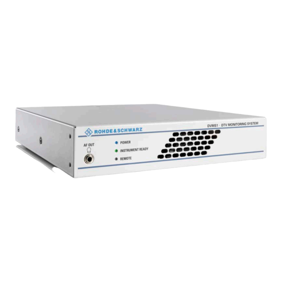
® Interfaces and Connectors R&S DVMS1 Front Panel 3 Interfaces and Connectors This chapter describes the front panel and the rear panel of the instrument, including all status displays and connectors. Some connectors may warm up slightly when high voltages are applied. As long as max- imum input levels are not exceeded, warm-up should not affect normal operation. -
Page 31: Connectors
® Interfaces and Connectors R&S DVMS1 Rear Panel 3.1.1.2 INSTRUMENT READY Displays the status of the R&S DVMS. ● LED off: R&S DVMS is currently not ready for operation. For example after powering up until the startup process is completed; the LED status display will change thereafter. -
Page 32: Ac Power Supply Connector
® Interfaces and Connectors R&S DVMS1 Rear Panel Fig. 3-2: Rear panel view (example) 3.2.1 AC Power Supply Connector The AC power supply connector and the AC power switch are combined. Switch positions: ● I: Depending on the setting of the On/Standby function key on the front panel, the instrument is either in standby mode or in operation. -
Page 33: Pps Ref In
® Interfaces and Connectors R&S DVMS1 Rear Panel 3.2.3 1 PPS REF IN This BNC jack is used as input for the 1PPS (1 pulse per second) reference pulse. The 1PPS reference pulse input of the R&S DVMS is used for measurement of network delay in DVB‑T distribution networks. -
Page 34: Lan Interface
® Interfaces and Connectors R&S DVMS1 Rear Panel Signal Signal DDC Data Not used Analog Vertical Sync TMDS Clock Shield TMDS Data 1- TMDS Clock+ TMDS Data 1+ TMDS Clock- TMDS Data 1 Shield Not used Not used Not used Not used Not used +5V Power... -
Page 35: Usb Interfaces
® Interfaces and Connectors R&S DVMS1 Rear Panel 3.2.6 USB Interfaces Two USB 2.0 interfaces of the type A (host USB) are provided (USB = universal serial bus). Use the interfaces to connect external devices like a keyboard, mouse, printer, or memory stick. -
Page 36: Dvb-T / Dvb-T2 Receiver Module (R&S Dvms-B55)
® Interfaces and Connectors R&S DVMS1 Rear Panel The status of the connectors is indicated by LEDs. Before showing a new state, each LED holds the current state for at least one second, if the current state is not "off" or "flashing". - Page 37 ® Interfaces and Connectors R&S DVMS1 Rear Panel Fig. 3-4: DVB-T/T2 receiver module The status of the connectors is indicated by LEDs. Before showing a new state, each LED holds the current state for at least one second, if the current state is not "off" or "flashing".
-
Page 38: Dvb-T2 Receiver Module (R&S Dvms-B54)
® Interfaces and Connectors R&S DVMS1 Rear Panel An LED indicates the TS OUT status: ● LED off: Output is currently not used. ● LED blue: Output is used as loop output. 3.2.9 DVB-T2 Receiver Module (R&S DVMS-B54) The T2 receiver module (R&S DVMS‑B54) is an option module. Fig. -
Page 39: Single Ts Input Module (R&S Dvms-B11)
® Interfaces and Connectors R&S DVMS1 Rear Panel TS OUT This BNC socket provides an MPEG2 transport stream signal conforming to the DVB‑ASI (EN 50083‑9 (2002)) interface standard. The interface is used as a loop output for a transport stream signal from the RF IN or TS IN input (see above). -
Page 40: S/S2 Receiver Module (R&S Dvms-B51)
® Interfaces and Connectors R&S DVMS1 Rear Panel To select the input, in the toolbar, click "Instrument Configuration" and then select "Signal Interface". For details see for details see the user manual or help system. An LED indicates the TS OUT status: ●... -
Page 41: Ts/Ip Interface Module (R&S Dvms-B40)
® Interfaces and Connectors R&S DVMS1 Rear Panel ● LED yellow: Input is used for monitoring but synchronization cannot be achieved. TS OUT This BNC socket provides an MPEG2 transport stream signal conforming to the DVB‑ASI (EN 50083‑9 (2002)) interface standard. The interface is used as a loop output for a transport stream signal from the RF IN or TS IN input (see above). - Page 42 ® Interfaces and Connectors R&S DVMS1 Rear Panel ● LED yellow: Connector is used as an input for monitoring but synchronization cannot be achieved. To help locating a connector socket, you can let its status LED flash ("Instrument Con- figuration" dialog, "Signal Interfaces" tab; for details see the user manual or help system). 1000 BASE-T This 1000 Base‑T Gigabit interface socket is used either as an input for IP and TS mon- itoring (IP in flow) or as IP loop output (IP out flow) for encapsulated MPEG2 transport...
-
Page 43: Connecting The Instrument
® Connecting the Instrument R&S DVMS1 Connecting to the AC Power Supply 4 Connecting the Instrument This chapter describes how to connect the instrument to the power supply and external devices. Preventing electromagnetic interference Use only suitable and shielded signal/control cables. These cables should have at least 80 dB to 1 GHz shielding. - Page 44 ® Connecting the Instrument R&S DVMS1 Connecting External Devices ● Memory stick for easy transfer of data to/from a computer (e.g. firmware updates). ● CD–ROM drives for easy installation of firmware applications. ● Printer for printing out measurement results. To install a USB device 1.
-
Page 45: Switching On Or Off The Instrument
® Switching On or Off the Instrument R&S DVMS1 Switching On the Instrument 5 Switching On or Off the Instrument Shock hazard Observe the basic safety instructions at the beginning of this manual, especially the instructions on electrical safety. 5.1 Switching On the Instrument Risk of instrument damage Before switching on the instrument, make sure that the following conditions are met: ●... -
Page 46: Switching Off The Instrument
® Switching On or Off the Instrument R&S DVMS1 Switching Off the Instrument 5.2 Switching Off the Instrument Risk of losing data If you switch off the running instrument using the rear panel switch or by disconnecting the power cord before shutting it down, the instrument loses its current settings. Further- more, program data may be lost. -
Page 47: Sample Application
® Sample Application R&S DVMS1 Requirements 6 Sample Application Follow the instructions in this chapter to perform your first measurement with the R&S DVMS. For an expanded selection of measurement examples and background information refer to the user manual or the help system. In this measurement, the R&S DVMS is used for basic compliance checks of one single MPEG2 transport stream (TS) signal. -
Page 48: Creating A Basic Configuration
® Sample Application R&S DVMS1 Creating a Basic Configuration 6.3 Creating a Basic Configuration In the TS Analyzer monitoring application, create the basic configuration. 1. In the toolbar, select "Instrument Configuration" to open the "Instrument Configura- tion" dialog. 2. On the "Signal Interface" tab, select the following: a) In the "Interface Settings"... -
Page 49: Performing The Measurement
® Sample Application R&S DVMS1 Performing the Measurement 2. In the "View Selector" dialog, click the icon for the Statistics & Log measurement. 3. Click "Control" and select "Clear Statistics & Log". 4. Under "1st Priority Error", check the "TS Sync" statistics counter. ●... -
Page 50: Checking The Gross Bit Rate Of The Connected Ts
® Sample Application R&S DVMS1 Performing the Measurement 6.5.1 Checking the Gross Bit Rate of the Connected TS 1. In the toolbar, click "View Selector". 2. In the "View Selector" dialog, click the icon for the Bit Rate measurement. 3. Read the current bit rate of the connected TS from the TS elements table. The value is given in units of Megabits per Second (Mbit/s). - Page 51 ® Sample Application R&S DVMS1 Performing the Measurement Fig. 6-1: Extended Checks I tab 3. In the first line, activate the "Bit Rate" option for overall bit rate limits monitoring. 4. The second line shows the current (default) settings for the monitoring TS bit rate. To modify the calculation method, do the following: a) Activate the "TS"...
-
Page 52: Activating The Monitoring Error For Ts Bit Rate Monitoring
® Sample Application R&S DVMS1 Performing the Measurement Fig. 6-2: Monitoring view 7. Compare this value to the gross value from before (see c hapter 6.5.1, "Checking the Gross Bit Rate of the Connected TS", on page 32). Since only the packet payload of all TS packets is examined for net bit rate calculation, the net value should be lower by a factor of approximately 184/188. - Page 53 ® Sample Application R&S DVMS1 Performing the Measurement 7. Check the monitoring log. Every second, "Bite Rate - TS bit rate higher than specified limit" log entries are inserted at the end of the log. In addition, the "Bit Rate" statistics counter is incre- mented every second.
-
Page 54: Checking The Content Of The Psi Table Pat
® Sample Application R&S DVMS1 Performing the Measurement 6.5.4 Checking the Content of the PSI Table PAT PAT is used as abbreviation for Program Association Table as specified in the associated MPEG2 standard ISO/IEC13818‑1. 1. In the toolbar, click "View Selector". 2. -
Page 55: Operating The Instrument In A Lan
® Operating the Instrument in a LAN R&S DVMS1 Connecting the Instrument to the Network 7 Operating the Instrument in a LAN The R&S DVMS is equipped with a network interface and can be connected to an Ether- net LAN (local area network). Provided the appropriate rights have been assigned and the Window XP firewall configuration is adapted accordingly, the interface can be used e.g. -
Page 56: Configuring The Network Card
® Operating the Instrument in a LAN R&S DVMS1 Configuring the Network Card 2. Make sure that the R&S DVMS is switched off. This is the only way to ensure that the network connection is reliably detected and any disruptions during the operation of the R&S DVMS are avoided. -
Page 57: Configuring The Simple Network Management (Snmp) Agent
® Operating the Instrument in a LAN R&S DVMS1 Configuring the Simple Network Management (SNMP) Agent 7.4 Configuring the Simple Network Management (SNMP) Agent The "Instrument Configuration" dialog, "System Settings" tab gives access to the SNMP configuration settings. For details refer to the user manual or help system, chapter "Configurations". Getting Started 2113.7619.02 ─... -
Page 58: Installed Software
® Installed Software R&S DVMS1 Operating System 8 Installed Software The firmware and the operating system are already installed on the R&S DVMS. For further information: ● Performing a firmware update: see the Release Notes. ● Installing software options: see the user manual or the help system. 8.1 Operating System The R&S DVMS is equipped with the Windows XP Embedded operating system. -
Page 59: Windows Xp Start Menu
® Installed Software R&S DVMS1 Additional Software 8.1.2 Windows XP Start Menu The Windows XP Start menu provides access to the Windows XP functionality and installed programs. Under "Control Panel", the system settings are grouped. For details refer to the Windows XP help system. 8.2 Additional Software Risk of causing instrument unusability The instrument is equipped with the Windows XP operating system. -
Page 60: Prerequisite For The Recovery And Backup
® Installed Software R&S DVMS1 Windows XP Recovery and Backup Partition 8.3.1 Prerequisite for the Recovery and Backup As a prerequisite for a backup/restore process, in the BIOS settings, the hardware watch- dog must be disabled. Otherwise the backup/restore process (which normally lasts about 10 to 15 minutes) will be terminated and fail due to a reboot issued by the watchdog after about 4 minutes. - Page 61 ® Installed Software R&S DVMS1 Windows XP Recovery and Backup Partition 5. In "Integrated Peripherals", change the "Watch Dog Timer Select" setting to "Disa- bled". 6. Return to the main page and select "Save & Exit Setup" to store the changes and proceed with the system boot.
-
Page 62: Displaying The Windows Xp Recovery And Backup Partition Dialog
® Installed Software R&S DVMS1 Windows XP Recovery and Backup Partition 7. Continue as described in c hapter 8.3.2, "Displaying the Windows XP Recovery and Backup Partition Dialog", on page 44. After a successful boot with the default option "Firmware" in the boot dialog or a restored backup, the hardware watchdog will automatically be re-enabled by the R&S DVMS sys- tem software. -
Page 63: Backing Up The Current System Partition
® Installed Software R&S DVMS1 Windows XP Recovery and Backup Partition To continue see one of the following chapters: The ● c hapter 8.3.3, "Backing Up the Current System Partition", on page 45 The ● c hapter 8.3.4, "Recovering the Selected Version of System Partition", on page 46 The ... -
Page 64: Recovering The Selected Version Of System Partition
® Installed Software R&S DVMS1 Windows XP Recovery and Backup Partition 3. Click "Make Backup". After the backup, the "Windows XP Embedded Recovery and Backup Partition" dia- log is displayed again. 4. Click "Exit and Shutdown". 5. Turn off/on the R&S DVMS manually. 8.3.4 Recovering the Selected Version of System Partition 1. -
Page 65: Recovering The Factory Default
® Installed Software R&S DVMS1 Windows XP Recovery and Backup Partition 3. Under "Select Backup", select the backup to be restored. 4. Click "Restore" and follow the instructions. 5. After the recovery, turn off/on the R&S DVMS manually. 8.3.5 Recovering the Factory Default 1. -
Page 66: Deleting Backups
® Installed Software R&S DVMS1 Windows XP Recovery and Backup Partition 3. Click "Recover now" and follow the instructions. 4. After the recovery, turn off/on the R&S DVMS manually. 8.3.6 Deleting Backups On the recovery partition, you can store up to five backups in addition to the factory default. - Page 67 ® Installed Software R&S DVMS1 Windows XP Recovery and Backup Partition 3. Under "Select Backup", select the backup to be deleted. 4. Click "Remove". After the deletion, the R&S DVMS returns to the "Remove Backup" dialog as long as backups are still available. If the last backup is deleted, the "Windows XP Recovery and Backup Partition"...
-
Page 68: Maintenance
® Maintenance R&S DVMS1 Cleaning the Instrument 9 Maintenance The R&S DVMS does not need a periodic maintenance. Clean the outside of the instru- ment when necessary and check the rated data from time to time. If any problem arises, contact one of our customer support centers. The addresses of our customer support centers are provided at the beginning of this manual. -
Page 69: Storing The Instrument
® Maintenance R&S DVMS1 Storing the Instrument To replace the fuses 1. Open the lid of the AC power connector. 2. Lift the fuse holder out of its slot. 3. Exchange the two fuses. 4. Put the fuse holder back in its slot and close the lid. 9.3 Storing the Instrument The storage temperature range of the R&S DVMS is given in the data sheet. -
Page 70: Index
® Index R&S DVMS1 Index Symbols Fuse replacing ..............50 1 PPS REF IN connector ..........15 10 MHz REF IN connector ..........14 Getting started manual ............7 AC power supply connector ..........14 AC power switch .............. 14 Help system .............. - Page 71 ® Index R&S DVMS1 Packing the instrument ............ 51 Warranty ................10 Password Windows XP ..............40 Windows XP .............. 40 administrator ID ............40 POWER status display ............ 12 backing up system partition ........45 Power supply deleting system partition backups ......48 connecting to ............
Need help?
Do you have a question about the R&S DVMS1 and is the answer not in the manual?
Questions and answers