Table of Contents
Advertisement
Quick Links
TCD210002AF
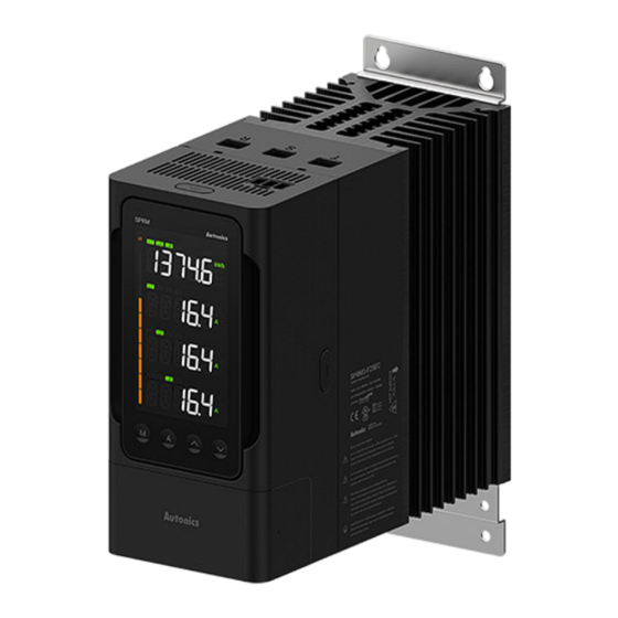
Multi-channel
Power Controllers
SPRM Series
PRODUCT MANUAL
For your safety, read and follow the considerations written in the instruction
manual, other manuals and Autonics website.
The specifications, dimensions, etc. are subject to change without notice for product
improvement. Some models may be discontinued without notice.
Features
• Single-phase control / three-phase control
• Supports a wide range of rated voltages from 220 to 440 VACᜠ
• Various rated current models of 25 / 40 / 55 / 70 / 90 / 110 / 160 A
• Improved visibility with 4-line LCD display
• Monitoring load current / voltage / output / resistance / heatsink temperature / power
• Detachable display module can be installed on a separate panel
• Supports various alarms, heater brake, partial heater brake, fuse break, heatsink over
heat, overcurrent, FAN error, etc. and saving alarm history
• Improved fuse replacement convenience with open/close structure
• Supports RS485, EtherCAT communication
ᜢ ᜨ ᜣ
Safety Considerations
• Observe all 'Safety Considerations' for safe and proper operation to avoid hazards.
• symbol indicates caution due to special circumstances in which hazards may
occur.
Warning
Failure to follow instructions may result in serious injury or death.
01. Fail-safe device must be installed when using the unit with machinery that
may cause serious injury or substantial economic loss.(e.g. nuclear power
control, medical equipment, ships, vehicles, railways, aircraft, combustion
apparatus, safety equipment, crime / disaster prevention devices, etc.)
Failure to follow this instruction may result in personal injury, economic loss or fire.
02. Do not use the unit in the place where flammable / explosive / corrosive gas,
high humidity, direct sunlight, radiant heat, vibration, impact or salinity may
be present.
Failure to follow this instruction may result in explosion or fire.
03. Install on the device panel, and ground to the bolt for grounding separately.
Failure to follow this instruction may result in fire or electric shock.
04. Do not connect, repair, or inspect the unit while connected to a power source.
Failure to follow this instruction may result in fire or electric shock.
05. Check 'Connections' before wiring.
Failure to follow this instruction may result in fire.
06. Do not disassemble or modify the unit.
Failure to follow this instruction may result in fire or electric shock.
Caution
Failure to follow instructions may result in injury or product damage.
01. Use the unit within the rated specifications.
Failure to follow this instruction may result in fire or product damage.
02. Use a dry cloth to clean the unit, and do not use water or organic solvent.
Failure to follow this instruction may result in fire or electric shock.
03. Keep the product away from metal chip, dust, and wire residue which flow
into the unit.
Failure to follow this instruction may result in fire or product damage.
04. Since leakage current still flows right after turning off the power or in the
output OFF status, do not touch the load terminal.
Failure to follow this instruction may result in electric shock.
05. Be careful not to injure the edges of the heat sink.
Cautions during Use
• Follow instructions in 'Cautions during Use'. Otherwise, it may cause unexpected accidents.
• Power supply should be insulated and limited voltage / current or Class 2, SELV power
supply device.
• Use the product, after 3 sec of supplying power.
• Before use, set the mode and function according to the specification. Since changing the
mode / parameter during operation may result in malfunction, set the mode and function
after disconnecting load output.
• Re-supply the power to the unit after 3 sec of turning off the power. Failure to follow this
instruction may result in malfunction.
• To ensure the reliability of the product, install the product on the panel or metal surface
vertically to the ground.
• Install the unit in the well ventilated place.
• While supplying power to the load or right after turning off the power of the load, do not
touch the body and heat sink. Failure to follow this instruction may result in a burn due to
the high temperature.
• Install a power switch or circuit breaker in the easily accessible place for supplying or
disconnecting the power.
• Do not wire to terminals which are not used.
• Use twisted pair wire for communication line.
• When connecting the display module and the main body with a LAN cable (direct / cross
cable), be careful not to generate excessive tension. Poor contact may cause malfunction of
the display.
• Since inter element can be damaged when using with coil load, inductive load, etc., the
inrush current must be under the rated load current.
• To prevent product malfunction due to noise, wire power, control input, communication,
and load cables separately.
• When installing close to the load line, use a line filter for the power line and use a shield wire.
Advertisement
Table of Contents

Related Manuals for Autonics SPRM Series


Summary of Contents for Autonics SPRM Series
- Page 1 • Install a power switch or circuit breaker in the easily accessible place for supplying or disconnecting the power. manual, other manuals and Autonics website. • Do not wire to terminals which are not used. The specifications, dimensions, etc. are subject to change without notice for product •...
-
Page 2: Ordering Information
Use a ferrite core on the shield wire to cope with EMC. • Do not use near the equipment which generates strong magnetic force or high frequency noise. • Unit: mm, For the detailed drawings, follow the Autonics website. • This unit may be used in the following environments. -
Page 3: Specifications
-|Transparent Guide|- Specifications Unit Descriptions • The configuration of each model may differ depending on the supported Model SPRM3-F□R SPRM3-F□EC specifications. Control phases Single phase 3 Ch or 3-phase [Top] [Bottom] Rated load voltage Free voltage 220 - 440 VACᜠ 50 / 60 Hz 25 / 40 / 55 / 70 / 90 / 110 / 160 A Rated load current Display method... - Page 4 -|Transparent Guide|- Connections ■ Suitable specifications • The following connectors can be used with equivalent or substitute. • The configuration of each model may differ depending on the supported Connector Connector specifications Manufacture specifications. EtherCAT communication RJ45 connector ■ EtherCAT communication connector RS485 communication 0225-0806 Control input...
- Page 5 -|Transparent Guide|- Mode Setting Alarm By setting parameters, you can set whether to use each alarm and relay output. → Setting check mode → [M + ▲] 2 sec [M] 2 sec ■ Overcurrent alarm → Program setting mode → [M] 2 sec [M] 2 sec It can protect the load/fuse from overcurrent.
-
Page 6: Parameter Setting
-|Transparent Guide|- Parameter Setting • Some parameters are activated / deactivated depending on the model or setting of other parameters. Refer to the description of each parameter. • Do not change parameters during output. • If any key is not entered for 60 sec in each parameter, it returns to RUN mode. •... - Page 7 -|Transparent Guide|- ■ Program setting mode 1-1. Single- According to 3PH ON / OFF of single-phase / 3-phase, LINE2 of the following parameters is displayed as 3PH / L1, L2, L3, ALL. • ALL = L1 + L2 + L3 + 3PH phase / 3-phase LINE1...
- Page 8 -|Transparent Guide|- 1-8. Output When the output current limit is over, the output turns OFF. current LINE1 C-LM limit According to 1-1. Single-phase / LINE2 3-phase setting (default: 3PH) LINE3 1.0 to 110.0 % of rated current [A] LINE4 1-9. Input slope It prevents load damage by limiting 100% of the power supplied to the load.
-
Page 9: Alarm Setting Mode
-|Transparent Guide|- ■ Alarm setting mode Sets whether to use an alarm for each situation, delay time, relay output, and whether to use automatic recovery. 2-1. Overcurrent LINE1 alarm LINE2 According to 1-1. Single-phase / 3-phase setting (default: 3PH) LINE3 ENABL: Enable / Disable LMT-C: Limit output current value DLY-T: Alarm delay time... -
Page 10: Control Method
-|Transparent Guide|- Function Control Method ■ Output high / low-limit value ■ Phase control This function is to limit output range to protect load. Phase control method is to control output by dividing AC phase by control input signal. • Normal = Phase equal division method by control input Output [%] Output high-limit 80 % It is general output method to divide control... -
Page 11: Segment Table
Segment Table The segments displayed on the product indicate the following meanings. It may differ depending on the product. 7 segment 11 segment 12 segment 16 segment 18, Bansong-ro 513Beon-gil, Haeundae-gu, Busan, Republic of Korea, 48002 www.autonics.com | +82-2-2048-1577 | sales@autonics.com...
Need help?
Do you have a question about the SPRM Series and is the answer not in the manual?
Questions and answers