Autonics SPR1 Series User Manual For Communication
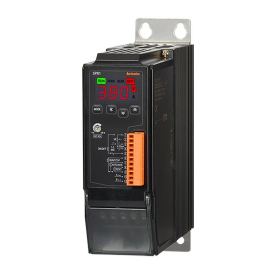
Led display slim power controller
Hide thumbs
Also See for SPR1 Series:
- User manual (15 pages) ,
- Instruction manual (2 pages) ,
- User manual for communication (26 pages)
Table of Contents
Advertisement
Quick Links
Advertisement
Table of Contents

Related Manuals for Autonics SPR1 Series


Summary of Contents for Autonics SPR1 Series
- Page 1 © Copyright Reserved Autonics Co., Ltd.
- Page 2 © Copyright Reserved Autonics Co., Ltd.
-
Page 3: Preface
Preface Preface Thank you for purchasing an Autonics product. Please familiarize yourself with the information contained in the Safety Considerations section before using this product. This user manual contains information about the product and its proper use, and should be kept in a place where it will be easy to access. -
Page 4: User Manual Guide
The manual's content may vary depending on changes to the product's software and other unforeseen developments within Autonics, and is subject to change without prior notice. Upgrade notice is provided through out homepage. We contrived to describe this manual more easily and correctly. However, if there are any ... -
Page 5: Communication Protocol
Communication Protocol Communication Protocol SPR1 Series is accepted to Modbus RTU Protocol. Users should be aware that it does not support a broadcast command. © Copyright Reserved Autonics Co., Ltd. -
Page 6: User Manual Symbols
Failure to follow instructions can result in serious injury or death. Failure to follow instructions can lead to a minor injury or product damage. An example of the concerned feature's use. Annotation mark. ※1 © Copyright Reserved Autonics Co., Ltd. -
Page 7: Safety Considerations
do not touch the load terminal. Failure to follow this instruction may result in electric shock. The specifications of communication manual are subject to change and some models may be discontinued without notice. © Copyright Reserved Autonics Co., Ltd. - Page 8 Safety Considerations viii © Copyright Reserved Autonics Co., Ltd.
-
Page 9: Table Of Contents
2.4 Read holding registers (Func 03) / Preset single register (Func 06) / Preset multiple registers (Func 16) ................21 2.4.1 Parameter 1 group ..................21 2.4.2 Parameter 2 group ..................21 2.4.3 Communication control input ..............21 © Copyright Reserved Autonics Co., Ltd. -
Page 10: Table Of Contents
Table of Contents © Copyright Reserved Autonics Co., Ltd. -
Page 11: Modbus Rtu Protocol
Response (Slave) Data Data Error check (CRC16) Slave address Function Byte count (000008 to (000010 to High 000001) 000009) 11 H 01 H 02 H CD H 01 H ## H ## H © Copyright Reserved Autonics Co., Ltd. -
Page 12: Read Input Status (Func 02-02H)
Response (Slave) Data Data Error check (CRC16) Slave address Function Byte count (100008 to (100010 to High 100001) 100009) 11 H 02 H 02 H CD H 01 H ## H ## H © Copyright Reserved Autonics Co., Ltd. -
Page 13: Read Holding Registers (Func 03-03H)
Response (Slave) Data Data Error check (CRC16) Slave address Function Byte count High High High 11 H 03 H 04 H 02 H 2B H 00 H 64 H ## H ## H © Copyright Reserved Autonics Co., Ltd. -
Page 14: Read Input Registers (Func 04-04H)
Response (Slave) Data Data Error check (CRC16) Slave address Function Byte count High Low High High 11 H 04 H 04 H 00 H 0A H 00 H 14 H ## H ## H © Copyright Reserved Autonics Co., Ltd. -
Page 15: Force Single Coil (Func 05-05H)
## H Response (Slave) Starting address Preset data Error check (CRC16) Slave address Function High High High 11 H 05 H 00 H 00 H FF H 00 H ## H ## H © Copyright Reserved Autonics Co., Ltd. -
Page 16: Preset Single Register (Func 06-06H)
## H Response (Slave) Starting address Preset data Error check (CRC16) Slave address Function High High High 11 H 06 H 00 H 00 H 00 H 0A H ## H ## H © Copyright Reserved Autonics Co., Ltd. -
Page 17: Preset Multiple Registers (Func 16-10H)
(device) connecting with external devices such as PLC, Graphic Panel, except in the case of download that presets the minimum/maximum or basic value of parameter by Input specifications in PC Loader Program © Copyright Reserved Autonics Co., Ltd. -
Page 18: Exception Response-Error Code
E8 H 00 H 01 H ## H ## H Response (Slave) Error check (CRC16) Function Slave address Exception Code +80 H High 11 H 81 H 02 H ## H ## H © Copyright Reserved Autonics Co., Ltd. -
Page 19: Modbus Mapping Table
300111 (006E) Reserved 300112 (006F) Reserved 300113 (0070) Reserved 300114 (0071) Reserved 300115 (0072) Reserved 300116 (0073) Reserved 300117 (0074) Reserved 300118 (0075) Coil Status Start Address 0000 300119 (0076) Coil Status Quantity © Copyright Reserved Autonics Co., Ltd. - Page 20 Bit 0 Fuse Heater Over- Over- Element Heatsink break break voltage current error overheat 0 / 1 0 / 1 0 / 1 0 / 1 0 / 1 0 / 1 1Byte 1Byte © Copyright Reserved Autonics Co., Ltd.
-
Page 21: Read Holding Registers (Func 03) / Preset Single Register (Func 06) / Preset Multiple Registers (Func 16)
400071 to 400100 03/06/16 R/W Reserved 2.4.3 Communication control input Factory No(Address) Func R/W Parameter Description Setting Range Unit Note Default Initialized when Communication Communication control 400101 (0000) 03/06/16 R/W 0~100 resupplying input Input power © Copyright Reserved Autonics Co., Ltd. - Page 22 2 Modbus Mapping Table © Copyright Reserved Autonics Co., Ltd. MCY-SPRC1-V1.2-1807US...
Need help?
Do you have a question about the SPR1 Series and is the answer not in the manual?
Questions and answers