Advertisement
Quick Links
Advertisement

Subscribe to Our Youtube Channel
Related Manuals for Amada MH-1201A


Summary of Contents for Amada MH-1201A
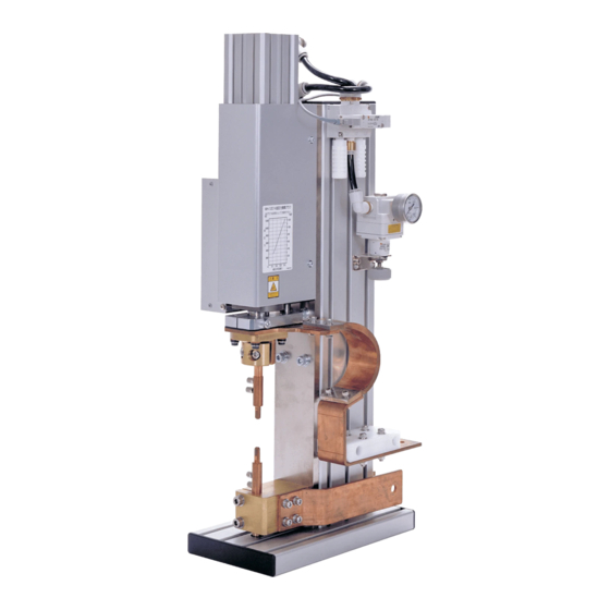
- Page 1 RESISTANCE WELDING HEAD MH-1201A OPERATION MANUAL Z09M0612E-07...
-
Page 2: Table Of Contents
MH-1201A Thank you for purchasing our Resistance Welding Head MH-1201A. ・ This operation manual explains its method of operation and precautions for use. ・ Before using, read this operation manual carefully; after reading, save it in a proper place where you can easily access. -
Page 3: Special Precautions
MH-1201A 1. Special Precautions (1) Safety Precautions CAUTION ! Before using, read "Safety Precautions" carefully to understand the correct method Denotes operations and practices that of use. may result in personal injury or damage to the equipment if not correctly followed. - Page 4 MH-1201A WARNING ! Do not put your hands between the electrodes When welding, keep your fingers and hands away from the electrodes. Do not touch any welded part or electrodes during welding and just after welding finished The welded part of a workpiece, electrodes and electrode holder are very hot.
- Page 5 MH-1201A CAUTION ! Apply the specified source voltage Application of a voltage out of the specified range can cause fire and electric shock. Do not splash water on the Welding Head Water splashed over the electric parts can cause electric shock and short circuits.
- Page 6 MH-1201A (2) Precautions for Handling ■ Do not install this Welding Head in the following: ・Damp places where humidity is 90% or higher, ・Dusty places, ・Places where chemicals are handled, ・Places near a high noise source, ・Hot or cold places where temperatures are above 40°C or below 5°C, and ・Places where water will be condensed.
-
Page 7: Features
MH-1201A 2. Features The MH-1201A Precision Resistance Welding Head has the following features: ■ Since the electrode force can be adjusted continuously, parameter setting can be made finely. ■ Since the response (follow-up) of the electrode is fast, explosive flashes and indentation are not produced, and the workpiece surfaces are finished clean. -
Page 8: Specifications And Accessories
MH-1201A 3. Specifications and Accessories (1) Specifications MH-1201A MH-1201A MH-1201A MH-1201A MH-1201A Items Electrode Force 300 to 1200 N (Approx. 30 to 120 kgf) (Continuously adjustable) Forcing Method Spring Electrode Provided None Electrode Diameter φ8 mm φ12 mm *1 Electrode Stroke... - Page 9 MH-1201A *1: The Electrode of the MH-1201A-50 is user provided. *2: The solenoid and regulator of the MH-1201A-20 are user provided. For the recommendation, see 6. Installation and Connection. *3: See “Welding Current vs. Duty Cycle” (p.3-2) for details of current and duty cycle.
- Page 10 Welding Head. ⑥ ③ ② Water-Cooled Shank-Fixing Screw ⑥ Secures the Water-Cooled Shank. Loosen ① for Electrode height adjustment. Head-Fixing Channel ⑦ For securing the MH-1201A onto work- bench. ⑤ ⑥ ⑦ Figure 4-1 4. Name and Functions of Each Section...
- Page 11 MH-1201A Side View Speed Controller 1 ⑧ Adjusts Electrode-Up speed. ⑧ Speed Controller 2 ⑨ Adjusts Electrode-Down speed. ⑨ Solenoid Valve ⑩ Changeover valve to control ⑩ the flow of air. Cooling Water Intake ⑪ Accepts the cooling water. Tube Specifications...
- Page 12 Solenoid Valve Cable ⑳ Feeds power to the solenoid valve. MH-1201A-10 has red cable (+) and black cable (-). Other models have no polarity. Fixing Screw for Electrode Holder (B) ○ Secures the Electrode Holder (B).
- Page 13 MH-1201A Figure 4-5 Load Cell Cable ○ Connects to the indicator. This is attached to the MH-1201A-41. 4. Name and Functions of Each Section...
- Page 14 MH-1201A Head-Mounting Hole ○ MH-1 201A -20 Rear Vie w M6 and 15 mm in depth. Feeder Terminal ○ Connects the secondary cable. Figure 4-6 4. Name and Functions of Each Section...
-
Page 15: Piping System Diagrams
MH-1201A 5. Piping System Diagrams Air Piping System Diagram Regulator B A CAUTION ! Do not touch the Electrode when feeding and exhausting high-pressure air The upper electrode may move forcefully; be careful not to have your hand and tools pinched. -
Page 16: Installation And Connection
Determine where to install the MH-1201A, welding power supply and welding transformer. (2) Drilling Mounting Holes Drill mounting holes on the workbench to secure the MH-1201A. When drilling, see the Head-Mounting Dimensions (Figure 6-2). (3) Positioning T-Nuts Place the T-Nuts at the determined positions referring to the drawing below. - Page 17 MH-1201A (4) Installing the MH-1201A Install the MH-1201A to the workbench with the attached hexagon socket head bolts, plain washers and spring washers. Use a proper tool suitable for the bolts to secure the Head. Head Mounting Holes Front Drillings on workbench...
- Page 18 Welding Power Supply MD-A4000A, Weld Checker, etc., connect the Voltage-Detecting Voltage- Cables ([SENS] cable) using the Detecting Connecting Threaded Holes. Cable ATTENTION The Voltage-Detecting Cables ([SENS] cable) are not attached to the MH-1201A. Please provide them. Figure 6-4 6. Installation and Connection...
- Page 19 MH-1201A (8) Connecting the Cooling Water Hoses and Air Tubes [Cooling Water Hose Connection] ATTENTION The Cooling Water Hoses (for feed and exhaust) are sold separately. Please provide them. Cut hose end right! Don't Figure 6-5 [Air Tube Connection] Regulator...
- Page 20 MH-1201A CAUTION ! If the high-pressure air contains residue or dust, the regulator will malfunction. Clean the air using an air filter or a mist separator. [Recommendation] Air filter: AF3000 ( SMC CORPORATION-made Mist separator: AFM3000 ( SMC CORPORATION-made ...
- Page 21 MH-1201A Description on pages 6-6 and -7 is for the MH-1201A-20. Users who are not using it don’t need to read these pages. (9) Mounting the MH-1201A-20 to the Frame Mount the MH-1201A-20 to the frame. Use a firm frame. When mounting,...
- Page 22 MH-1201A (10) Mounting the Flexible Feeder (or the Secondary Cable) Connect the flexible feeder (or the secondary cable) to the feeder terminal. When a stiff feeder is connected, the electrode does not move smoothly. ATTENTION Flexible feeder, secondary cable and screws are sold separately.
- Page 23 MH-1201A Description on this page is for the MH-1201A-41. Users who are not using them don’t need to read this page. (12) Connecting the Load Cell Cable to the Digital Indicator (NTS-4231) Connect the crimp-on terminal of the Load Cell Cable to the terminal block of the digital indicator.
-
Page 24: User's Maintenance
Do not use an electrode having a cut; it will cause water leak. Wipe off dust and stains with wastes. * The single open-ended spanner is not attached to the MH-1201A-50. Please provide tools of correct shape for the electrode. - Page 25 MH-1201A ⑥ Turn on the Main Circuit Breaker of the Welding Power Supply. ⑦ Secure fitting, i.e., engagement of the electrode and water-cooled shank, applying weld force several times. ATTENTION When applying weld force, be sure to turn off [WELD ON/OFF] switch.
- Page 26 MH-1201A ATTENTION The Weld Force Conversion Chart indicates the theoretical values. When measuring the actual weld force, use a pressure gauge. Weld Force Conversion Chart ( N ) ( k g f ) 1 2 0 0 1 2 0...
-
Page 27: Outline Drawing
MH-1201A 8. Outline Drawing MH-1201A-00 / MH-1201A-41 / MH-1201A-10 (Dimensions in mm) (50) 8. Outline Drawing... - Page 28 MH-1201A MH-1201A-20 (Dimensions in mm) 8-M6 15mm depth 8. Outline Drawing...
- Page 29 MH-1201A MH-1201A-50 (Dimensions in mm) (50) 30 (4) 8. Outline Drawing...
- Page 30 MH-1201A Digital Indicator (Nihon Tokushu Sokki Corporation-made NTS-4231) (Dimensions in mm) (24) 8. Outline Drawing...
Need help?
Do you have a question about the MH-1201A and is the answer not in the manual?
Questions and answers