Table of Contents
Advertisement
Advertisement
Table of Contents

Related Manuals for Amada SR-071A


Summary of Contents for Amada SR-071A
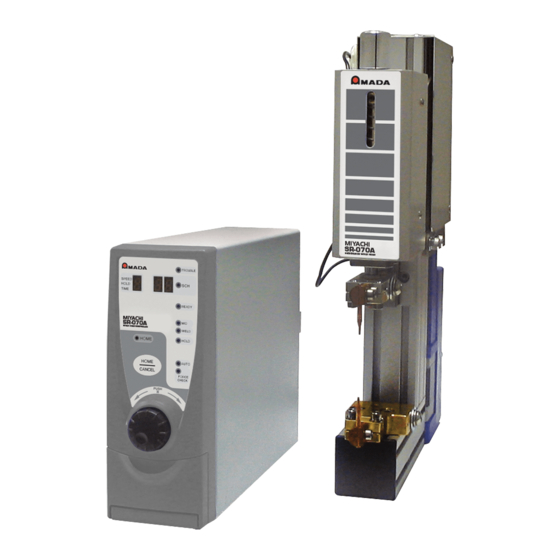
- Page 1 WELD HEAD SR-071A SR-072A SR-073A OPERATION MANUAL 990-143 REV K...
-
Page 2: Revision Record
Copyright © 2004 - 2020 Amada Weld Tech The engineering designs, drawings and data contained herein are the proprietary work of Amada Weld Tech and may not be reproduced, copied, exhibited or otherwise used without the written authorization of Amada Weld Tech. -
Page 3: Table Of Contents
Adjust the Electrode Mounting Angle ..................... 2-8 Chapter 3. Operating Instructions Section I: Before You Start Preparation ....................3-1 Preparation ............................3-1 Operator Safety ..........................3-1 Section II: Operation ..........................3-2 Overview ............................3-2 2-level Footswitch ........................... 3-2 SR-071A / SR-072A / SR-073A WELD HEADS 990-143... - Page 4 Appendix C. Timing ..........................C-1 Appendix D. Communication ......................D-1 Appendix E. Accessories ........................E-1 Appendix F. The Basics of Resistance Welding ................F-1 Appendix G. Quality Resistance Welding Solutions: Defining the Optimum Process ....F-1 SR-071A / SR-072A / SR-073A WELD HEADS 990-143...
-
Page 5: Foreword
The contents of this manual are subject to change without notice. Amada Weld Tech is not responsible for any loss or injury due to improper use of this product. This Manual covers the following models:... -
Page 6: Safety Precautions
The meanings of the words and symbols are as follows: DANGER NEVER DISASSEMBLE, REPAIR, OR MODIFY THE WELD HEAD. These actions can cause electric shock and fire. Do not do anything other than the maintenance described in this manual. SR-071A / SR-072A / SR-073A WELD HEADS 990-143... - Page 7 Stop operation if any trouble occurs. If you detect a burning smell, abnormal sounds, abnormal heat, smoke, etc., turn power OFF immediately to prevent fire or electric shock. Contact Amada Weld Tech or your distributor for help. People with pacemakers MUST stay away from the Weld Head.
- Page 8 Regularly inspect and maintain the Weld Head. Regular inspection and maintenance is essential to safe operation and long life of the equipment. If you see any damage, make necessary repairs before operation. SR-071A / SR-072A / SR-073A WELD HEADS viii 990-143...
- Page 9 Operate the button carefully by hand. If it is operated roughly or with the tip of a tool you may damage the Weld Head. Disposal Precaution The Motor Controller photo-coupler contains GaAs (Gallium Arsenide). Follow all local environmental regulations for disposal. SR-071A / SR-072A / SR-073A WELD HEADS 990-143...
-
Page 10: Warranty
1. Applicability. (a) These terms and conditions of sale (these “Terms”) are the only terms which govern the sale of the goods (“Goods”) by Amada Weld Tech Inc. (“Seller”) to the buyer identified in the Sales Quotation and/or Acknowledgment (as each defined below) to which these Terms are attached or incorporated by reference (“Buyer”). - Page 11 Agreement. Buyer shall immediately discontinue use of the Software upon any termination of this license or Agreement. This license shall terminate upon any termination of the Agreement. SR-071A / SR-072A / SR-073A WELD HEADS 990-143...
- Page 12 FORESEEN BY BUYER, REGARDLESS OF THE LEGAL OR EQUITABLE THEORY (CONTRACT, TORT OR OTHERWISE) UPON WHICH THE CLAIM IS BASED, AND NOTWITHSTANDING THE FAILURE OF ANY AGREED OR OTHER REMEDY OF ITS ESSENTIAL PURPOSE. SR-071A / SR-072A / SR-073A WELD HEADS 990-143...
- Page 13 19. Force Majeure. Seller shall not be liable or responsible to Buyer, nor be deemed to have defaulted or breached this Agreement, for any failure or delay SR-071A / SR-072A / SR-073A WELD HEADS 990-143...
- Page 14 27. Survival. Provisions of these Terms which by their nature should apply beyond their terms will remain in force after any termination or expiration of this Order including, but not limited to, the following provisions: Compliance with Laws, Confidentiality, Governing Law, Dispute Resolution, Survival, and the restrictions on Software in Sections 10(b), (c) and (d). SR-071A / SR-072A / SR-073A WELD HEADS 990-143...
-
Page 15: Chapter 1. Description
DESCRIPTION Section I: Features For the rest of this manual, SR-071A / SR-072A / SR-073A / SR-073A-Z Weld Heads will simply be referred to as the Weld Head. The Motor Control Unit will simply be referred to as The Controller. -
Page 16: Section Ii: Major Components
For mounting the Weld Head to the work bench. Two brackets are Head Bracket provided, each with 2/10” (5.5mm) mounting holes. Adapter Mounting Screws Secures the bottom Electrode Adapter to the Base. SR-071A / SR-072A / SR-073A WELD HEADS 990-143... -
Page 17: Model Sr-072A Weld Head
For mounting the Welding Head on the workbench. Six (6) holes are Base Mounting Holes. provided. Each hole is ¼-inch (6.5mm), with Ø.43-inch (11mm) spot facing, and Ø.4-inches (10mm) deep. Electrodes For spot welding. SR-071A / SR-072A / SR-073A WELD HEADS 990-143... -
Page 18: Model Sr-073A Weld Head
For mounting the Weld Head to the work bench. Two brackets are Head Bracket provided, each with 2/10” (5.5mm) mounting holes. Weld Cable Screw Secures the Weld Cable to the Electrode Holder Adapter. SR-071A / SR-072A / SR-073A WELD HEADS 990-143... -
Page 19: Model Sr-073A-Z Pincer Weld Head
CHAPTER 1: DESCRIPTION Model SR-073A-Z Weld Head SR-071A / SR-072A / SR-073A WELD HEADS 990-143... - Page 20 Plate for supplying Power Mounts a secondary cable. M8 Screws for fixing Secondary Cable Fixes a secondary cable. Cable for Weld Force Detecting Sensor Connects firing sensor to controller Motor Cable Connects motor to controller SR-071A / SR-072A / SR-073A WELD HEADS 990-143...
-
Page 21: Controller (Front Panel)
Operation button is selecting a function. Schedule No. can be changed TROUBLE Lamp Trouble is occurring. Electrode is at Weld Point. Lowest point (Downstop Point) is WELD Lamp being changed. Operation button is selecting a function. SR-071A / SR-072A / SR-073A WELD HEADS 990-143... -
Page 22: Operation Button
In case of Movement Mode 1, electrode position SPEED HOLD TIME is at Start Point and the Display shows “A’ when Display setting is not performed. ORG/CANCEL Button. This button interrupts the programming changes in progress. SR-071A / SR-072A / SR-073A WELD HEADS 990-143... -
Page 23: Controller (Rear Panel)
Used for connecting a power supply cable (separately sold) to 100 to Power Supply Connector 240 VAC power supply. Used as a ground terminal when you are not using a power supply Ground Terminal cable with a ground wire (sold separately). SR-071A / SR-072A / SR-073A WELD HEADS 990-143... -
Page 25: Chapter 2. Installation And Setup
The Welding Head base has six (6) holes so that it may be installed onto a work bench. Each hole is ¼- inch (6.5mm) in diameter, with Ø.43-inch (11mm) spot facing, and is Ø.4-inches (10mm) deep. SR-071A / SR-072A / SR-073A WELD HEADS 990-143... -
Page 26: Space Requirements
Space Requirements (not to scale) 18.4” (467mm) 11.9” (301mm) 3.1” 8.6” 4.7” 16” (80mm) (219mm) (120mm) (406mm) Model SR-071A Weld Head Model SR-072A Weld Head 18.4” (468mm) 10.8” 6.8” (274mm) (173mm) Model SR-073A Weld Head SR-071A / SR-072A / SR-073A WELD HEADS 990-143... -
Page 27: Install Electrodes
The example shown on the right shows the Model SR-072A for reference. 1. Loosen the Electrode Screw. Insert the Electrode into the Electrode Holder. 3. Tighten the Electrode Screw to secure the Electrode in place. SR-071A / SR-072A / SR-073A WELD HEADS 990-143... -
Page 28: Connect Weld Cables
Model SR-071A Model SR-072A Model SR-071A NOTES: ● These cables are not polarized. ● The connecting screws on Model SR-072A are on both the left and right sides of the head. SR-071A / SR-072A / SR-073A WELD HEADS 990-143... -
Page 29: Connect Controller And Power Supply Cables
Pins 21 and 22 of the I/O connector. Use the operation switch whose capacity is more than 24VDC, 20 mA. 4. Connect the AC Cable. Finally, connect the AC Cable to the 100—240VAC, 50/60 Hz outlet. SR-071A / SR-072A / SR-073A WELD HEADS 990-143... -
Page 30: Section Ii: Set-Up
Lock Screw to the desired weld force scale. 3. Tighten the lock screw to lock the Weld Force Adjust Knob. 4. After adjusting, measure the weld force using a pressure force gauge. SR-071A / SR-072A / SR-073A WELD HEADS 990-143... -
Page 31: Adjust Weld Head Position
Electrode Holders to align the upper and lower electrodes as shown at lower right. NOTE: If you can’t align the electrodes, loosen the Holder Screw to move the Electrode Holder up, down, left, or right as needed. SR-071A / SR-072A / SR-073A WELD HEADS 990-143... -
Page 32: Adjust The Electrode Mounting Angle
Electrode Holder Cover Insert the electrode into the slot of and adjust to desired Electrode Holder height. 3. Reinstall the Electrode Holder Covers When the are in place tighten Electrodes the screws securely. SR-071A / SR-072A / SR-073A WELD HEADS 990-143... - Page 33 Tighten the screws securely to prevent the cables from coming loose during operation. Attach Water Cooling Tubes Attach the tubes as shown below. NOTE: 6mm water cooling tubes are not supplied with the weld head. SR-071A / SR-072A / SR-073A WELD HEADS 990-143...
-
Page 35: Chapter 3. Operating Instructions
Verify that the Power Supply/Welding Control is turned Operator Safety DANGER • Always wear protective safety glasses when performing any welding operation. • Always wear appropriate personal protective gear when welding. SR-071A / SR-072A / SR-073A WELD HEADS 990-143... -
Page 36: Section Ii: Operation
Lamp lights up when the electrode is at this position and causes the Weld Point welding current to flow. A little bit beyond the position from Weld Point. It can be set Downstop Point arbitrarily. SR-071A / SR-072A / SR-073A WELD HEADS 990-143... -
Page 37: Electrode Working Mode
Weld Point, then the fault code “E” is displayed. In Case of Mode 0 When a problem occurs between Mid-Point and Start Point, open External Input to make the electrode move to Start Point. SR-071A / SR-072A / SR-073A WELD HEADS 990-143... -
Page 38: Mode Setting
“ ”. Press the button to fix. Operation Operation 10. Confirm ) and Display, which means the SCHEDULE SPEED HOLD TIME completion of setting. 11. Turn the power OFF. SR-071A / SR-072A / SR-073A WELD HEADS 990-143... -
Page 39: Applying Power And Moving To Start Point
10. When the application of the electrode force is completed, the electrode returns to the position before Original Point and the Controller beeps. 11. Open External Input to complete the auto-setting with a beep. The position where the electrode stops is Start Point. SR-071A / SR-072A / SR-073A WELD HEADS 990-143... -
Page 40: Manually Set The Electrode Position
The lamp will Operation READY blink fast. 14. Close the External Input ( ). The Start Point setting is completed and the Controller beeps. SR-071A / SR-072A / SR-073A WELD HEADS 990-143... -
Page 41: Changing Moving Speed Between Start Point And Mid-Point
Operation and backward in 0.1 mm-increment/decrement. 6. Press the button when the electrode reaches the desired position and the Lamp will Operation blink quickly. SR-071A / SR-072A / SR-073A WELD HEADS 990-143... -
Page 42: Setting Moving Speed From Mid-Point To Weld Point
Operation and backward in 0.1 mm-increment/decrement. 6. Press the button when the electrode reaches the desired position. The Lamp Operation WELD will blink quickly. SR-071A / SR-072A / SR-073A WELD HEADS 990-143... -
Page 43: In Case The Electrode Cannot Move Beyond The Weld Point Because Of A Workpiece
Operation blinking lamp. Select your desired period. Setting Additional Squeeze Time (ms) None (0) 4. Press the button when your desired period is indicated. Operation NOTE: Press the button to interrupt. ORG/CANCEL SR-071A / SR-072A / SR-073A WELD HEADS 990-143... -
Page 44: Setting Hold Time
. Check the Hold Time, observing the electrode that moves up and down. 5. Press the button when your desired Hold Time is determined. Operation NOTE: Press button to interrupt. ORG/CANCEL SR-071A / SR-072A / SR-073A WELD HEADS 3-10 990-143... -
Page 45: Setting Moving Speed From Weld Point To Mid-Point
4. Turn the button clockwise and counterclockwise to change the number of the blinking Operation lamp. Select your desired speed. Weld Point to Mid-Point Number Note Moving Speed (mm/sec) Minimum Maximum SR-071A / SR-072A / SR-073A WELD HEADS 990-143 3-11... -
Page 46: Section Iii. Welding
Operation FORCE CHK bar will appear on the Display, see explanation below. Model SR-071A & SR-073A: A horizontal bar “–” will light on the display. SPEED HOLD TIME Model SR-072A: A vertical bar “l” will light on the display. -
Page 47: Section I. Troubleshooting
Turn off the power and thereafter, turn it on again. Fault occurred in memory’s R/W- function in controller If the problem continues, contact Amada Weld Tech for repair. After turning off the power or resetting the fault signal, resume Start Point. -
Page 48: Service
CAUTION: Do not move the paper from side-to-side or in a circular motion or you may damage the electrodes. 4. Clean the electrode face with a small cotton swab saturated in alcohol. SR-071A / SR-072A / SR-073A WELD HEADS 990-143... - Page 49 3. Tighten the lock screw to secure the Weld Force Adjustment Knob After adjusting, measure the weld force by using a force gauge or spring balance. SR-071A / SR-072A / SR-073A WELD HEADS 990-143...
- Page 50 CHAPTER 4: MAINTENANCE Weld Force Conversion Graph This graph represents theoretical values. To measure the actual weld force, use a pressing force gauge or spring balance. SR-071A / SR-072A / SR-073A WELD HEADS 990-143...
-
Page 51: Appendix A. Technical Specifications
APPENDIX A TECHNICAL SPECIFICATIONS Specifications Item Description 11.9” (301mm) MODEL SR-071A Dimensions 3.1” 8.6” (80mm) (219mm) 18.4” (467mm) MODEL SR-072A Dimensions 4.7” 16” (120mm) (406mm) SR-071A / SR-072A / SR-073A WELD HEADS 990-143... - Page 52 APPENDIX A: SPECIFICATIONS Item Description 18.4” (468mm) MODEL SR-073A Dimensions 10.8” 6.8” (274mm) (173mm) 5.9” (148mm) 23.9” (606mm) MODEL SR-073A-Z 2.9” Dimensions (75mm) 5.0” (129mm) SR-071A / SR-072A / SR-073A WELD HEADS 990-143...
- Page 53 7 Settings Number of Weld 31 Schedules (Externally Selectable) Schedules Operating Temperature: 0° - 40°C, Humidity: 90% or less (No condensation) conditions Power Supply 100-240 VAC, ± 10%, 50/60 Hz, 70VA Voltage SR-071A / SR-072A / SR-073A WELD HEADS 990-143...
-
Page 55: Appendix B. Electrical And Data Connections
APPENDIX B ELECTRICAL AND DATA CONNECTIONS External Input / Output Signal Connections SR-071A / SR-072A / SR-073A WELD HEADS 990-143... - Page 56 EXAMPLE: When an NPN transistor (sink type) on a PLC is used as the input terminal of the I/O Connector. EXAMPLE: When a PNP transistor (source type) on a PLC is used as the input terminal of the I/O Connector. SR-071A / SR-072A / SR-073A WELD HEADS 990-143...
- Page 57 Although only 2 is closed, electrode does not move. Spare pin: Do not connect. Input Internally connected to GND ( 0V ). Output Output pins for 24 VDC through 100Ω internal resistor. SR-071A / SR-072A / SR-073A WELD HEADS 990-143...
- Page 58 Output pin for completion signal of being ready for work. When the resumption of Start Point is Output completed, the Pin becomes closed. If the Controller has an emergency, the Pin becomes opened. SR-071A / SR-072A / SR-073A WELD HEADS 990-143...
- Page 59 Common terminal to READY START POINT MID POINT ERROR Do not connect to the Pin for EXT. 24 V Input Internally connected to GND ( 0V ). Spare pin: Do not connect. SR-071A / SR-072A / SR-073A WELD HEADS 990-143...
-
Page 61: Appendix C. Timing
APPENDIX C TIMING Power ON and ERROR Indication Operation SR-071A / SR-072A / SR-073A WELD HEADS 990-143... -
Page 63: Appendix D. Communication
Connections RS-232C RS-232C signals use , and . The communication connector is inside the external connector cover. NOTE: are not used with the is not checked at the beginning of Controller communication. SR-071A / SR-072A / SR-073A WELD HEADS 990-143... - Page 64 . The communication connector is inside the external connector cover. NOTES: ● RS-485 operation requires a user-provided RS-232C-to-RS-485 converter/adapter. ● Mount a 100Ω terminal resistor at both ends of the RS-485 cable as shown above. SR-071A / SR-072A / SR-073A WELD HEADS 990-143...
- Page 65 04-04 Readout request Fixed 05-07 Schedule Number 001 to 031 08-08 All contents Fixed 09-09 CR code ( 0 x 0D ) Fixed 10-10 LF code ( 0 x 0A ) Fixed SR-071A / SR-072A / SR-073A WELD HEADS 990-143...
- Page 66 Mid- Point and Weld Point Additional Squeeze Time 34-34 1 - A at Weld Point 35-35 CR code ( 0 x 0D ) Fixed 36-36 LF code ( 0 x 0A ) Fixed SR-071A / SR-072A / SR-073A WELD HEADS 990-143...
- Page 67 Mid- Point and Weld Point Additional Squeeze Time 35-35 1 - A at Weld Point 36-36 CR code ( 0 x 0D ) Fixed 37-37 LF code ( 0 x 0A ) Fixed SR-071A / SR-072A / SR-073A WELD HEADS 990-143...
- Page 68 Mid- Point and Weld Point Additional Squeeze Time 34-34 1 - A at Weld Point 35-35 CR code ( 0 x 0D ) Fixed 36-36 LF code ( 0 x 0A ) Fixed SR-071A / SR-072A / SR-073A WELD HEADS 990-143...
-
Page 69: Appendix Eaccessories
Model SR-071A Model SR-072A Model SR-073A Model SR-073A-Z Electrodes ES0402 EU1000 ES0850 13-200-01-01 AMYA Part Number 13-003-04-02 11-008-10-02 Operator Manual Operator Manual for the SR-071A / SR-072A / SR-073A Weld Heads (990-143) SR-071A / SR-072A / SR-073A WELD HEADS 990-143... -
Page 71: Appendix F. The Basics Of Resistance Welding
RT -- the square of the weld current [ I ] times the workpiece resistance [ R ] times the weld time [ T ]. Welding Parameter Interaction Interaction of Welding Parameters SR-071A / SR-072A / SR-073A WELD HEADS 990-143... - Page 72 -2, -14 Brass -2, -14 Stainless Steel Copper Beryllium Copper Bronze -2, -11 Bronze -2, -11 Copper Beryllium Tinned Copper Bronze -2, -11 Tinned Copper Copper Beryllium Nickel Bronze -2, -11 Iron Copper SR-071A / SR-072A / SR-073A WELD HEADS 990-143...
- Page 73 Kovar, Gold Copper Karme Kulgrid Plate Kovar, Gold Copper Manganin Nickel Plate Kovar, Gold Copper Nichrome Silver -11, -14 Plate Kovar, Gold Copper Nickel Stainless Steel Plate Copper Paliney 7 Magnesium Magnesium SR-071A / SR-072A / SR-073A WELD HEADS 990-143...
- Page 74 If this is not done, the rough surface of the electrode face will have a tendency to stick to the work piece. SR-071A / SR-072A / SR-073A WELD HEADS 990-143...
- Page 75 Fatigue tests and radiography have also been used. Of these methods torsional shear is preferred for round wire and a 45-degree peel test for sheet stock. SR-071A / SR-072A / SR-073A WELD HEADS 990-143...
- Page 76 14lb electrode force curve. A comparison of weld schedules for several different applications might show that they could be consolidated into one or two weld schedules. This would have obvious manufacturing advantages. SR-071A / SR-072A / SR-073A WELD HEADS 990-143...
-
Page 77: Appendix G. Quality Resistance Welding Solutions: Defining The Optimum Process
Ceramic: alumina, sand • Plastics / polymers: PVC, Teflon • Semiconductors: silicon, geranium Metals can be resistance-welded because they are electrically conductive, soften on heating, and can be forged together without breaking. SR-071A / SR-072A / SR-073A WELD HEADS 990-143... - Page 78 As there is no real melting of the materials in a solid-state joint there is less chance of weld splash or material expulsion. A weld nugget can still be achieved with a solid-state joint. SR-071A / SR-072A / SR-073A WELD HEADS 990-143...
- Page 79 Conductive metals dissipate heat and it can also be difficult to focus heat at the interface. A solid-state joint is therefore preferred. Typically resistive electrode materials are used to provide additional heating. SR-071A / SR-072A / SR-073A WELD HEADS 990-143...
- Page 80 Bulk Resistance Time The figure above shows the key resistances in a typical opposed resistance weld and the relationship between contact resistances and bulk resistances over time, during a typical resistance weld. SR-071A / SR-072A / SR-073A WELD HEADS 990-143...
- Page 81 The contact resistance present at the weld when the power supply is fired has a great impact on the heat balance of a weld and therefore also the heat affected zone. SR-071A / SR-072A / SR-073A WELD HEADS 990-143...
- Page 82 The basic welding profile or schedule consists of a controlled application of energy and force over time. Precision power supplies control the energy, time, and therefore heating rate of the parts. The weld head applies force from the start to finish of the welding process. SR-071A / SR-072A / SR-073A WELD HEADS 990-143...
- Page 83 The main welding parameters such as energy, force, and time cannot be fixed at this stage but many of the other variables such as repeatable part positioning should be fixed. SR-071A / SR-072A / SR-073A WELD HEADS 990-143...
- Page 84 What other parameters will operators are able to adjust? • What are the quality and inspection requirements? • What are the relevant production testing methods and test equipment? • Do we have adequate control over the quality of the materials? SR-071A / SR-072A / SR-073A WELD HEADS 990-143...
- Page 85 The figure above shows common welding problems that can often be identified in the basic set up of the force, energy and time welding profile. These problems can lead to weld splash and inconsistency and variation (contact Amada Weld Tech for further information and support). SR-071A / SR-072A / SR-073A WELD HEADS...
- Page 86 If many variables are still not understood, multiple Screening DOE’S may be required. Amada Weld Tech provides a simple Screening DOE tool that is run in excel and is sufficient for the majority of applications (contact us for details). Bespoke sophisticated software is also available from other vendors designed specifically for this purpose.
- Page 87 Amada Weld Tech will frequently use the Screening DOE tool to establish the impact of key variables and also to assist customers with troubleshooting. Often the testing as described above will provide the information and understanding to predict common failure modes and causes.
- Page 89 TEL. +1-626-303-5676 FAX, +1-626-358-8048 http://www.amadaweldtech.com AMADA WELD TECH CO., LTD. 200, Ishida, Isehara-shi, Kanagawa 259-1196, Japan AMADA WELD TECH KOREA CO., LTD. 28, Dongtanhana 1-gil, Hwaseong-si, Gyeonggi-do, 18423, Korea TEL. +82-31-8015-6810 FAX. +82-31-8003-5995 AMADA WELD TECH SHANGHAI CO., LTD. Unit 401, A206(C8), No. 77, Hongcao Road, Xuhui District, Shanghai, China TEL.
- Page 90 AMADA WELD TECH INC. 1820 South Myrtle Ave., Monrovia, CA 91016, U.S.A. TEL. +1-626-303-5676 FAX. +1-626-358-8048...
Need help?
Do you have a question about the SR-071A and is the answer not in the manual?
Questions and answers