
Subscribe to Our Youtube Channel
Related Manuals for Amada MD-A4000B-05 Series


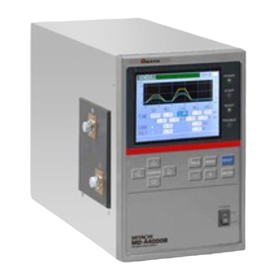
Summary of Contents for Amada MD-A4000B-05 Series
- Page 1 Original instructions TRANSISTOR WELDING POWER SUPPLY MD-A4000B-05-□□ MD-A1000B-05-□□ MD-B2000B-05-□□ MD-C2000B-05-□□ OPERATION MANUAL AA01OM1185329-08...
- Page 2 MD Series Thank you for purchasing our MD Series, Transistor Welding Power Supply. For correct use, read this Operation Manual carefully. After reading, save it properly for future reference. Contents Special Precautions ......................1-1 (1) Safety Precautions....................... 1-1 (2) Precautions for Handling ..................... 1-4 (3) On Disposal .........................
- Page 3 MD Series (4) Major Components List ....................10-7 (5) Schematic ........................10-7 11. Outline Drawing ......................11-1 12. Schedule Data Table ..................... 12-1 Index ............................1 EU Declaration of Conformity Contents...
- Page 4 MD Series 1. Special Precautions (1) Safety Precautions Before using, read "Safety Precautions" carefully to understand the correct method of use. These precautions are shown for safe use of our products and for prevention of ■ damage or injury to operators or others. Be sure to read each of them, since all of them are important for safety.
- Page 5 MD Series WARNING ! Do not put your hands between the electrodes When welding, keep your fingers and hands away from the electrodes. Do not touch any welded part or electrodes during welding and just after welding finished The welded part of a workpiece, electrodes and arm are very hot. Do not touch them;...
- Page 6 MD Series CAUTION ! Do not splash water on the Power Supply Water splashed over the electric parts can cause electric shock and short circuits. Use proper tools (wire strippers, pressure wire connectors, etc) for termination of the connecting cables Do not cut the conductor of wire.
- Page 7 MD Series (2) Precautions for Handling When transporting or moving the Power Supply, do not lay it down. Also, ■ handle the Power Supply with care so as not to make an impact such as drop on it. Install this Welding Power Supply on a firm and level surface. If it is inclined, ■...
- Page 8 MD Series (4) Function Difference Depending on Model Model Power supply voltage Type MD-A1000B-05-30 100 – 120V AC Standard type MD-A1000B-05-31 200 – 240V AC MD-A4000B-05-30 100 – 120V AC Standard type MD-A4000B-05-31 200 – 240V AC MD-B2000B-05-30 100 – 120V AC Polarity switching type MD-B2000B-05-31 200 –...
- Page 9 MD Series 2. Features MD-A1000B, MD-A4000B, MD-B2000B, and MD-C2000B are transistor welding power supplies for precision welding. Small power supply units can be used since all welding is powered by energy accumulated in a capacitor. MD-A1000B/A4000B: Standard type MD-B2000B: Polarity switching type MD-C2000B: Two-channel type The switching method adopted for welding current control permits the small model to ■...
- Page 10 MD Series 3. Packaging (1) Accessories Item Model No. Q’ty Operation manual AS1185841(OM1185328,OM1185329) (2) Options Item Model No. KP-35 KS-16A SVT#18 x 3 100 to 120V AC B-TYPE (3-pin plug) KP244 VCTF3*1.25 KS16D 3m Power cable 200V AC gray (for Japan) CEE3P-W-1.8 200 to 240V AC (Round-shaped plug)
- Page 11 MD Series 4. Name and Functions of Each Section (1) Front Panel ①Display screen ④READY lamp ③START lamp ⑤TROUBLE lamp ②POWER lamp ⑥WELD key/lamp ⑧MENU key ⑦Cursor key ⑨RESET key ⑩ENTER key ⑪+ key ⑫- key ⑬POWER switch 4. Name and Functions of Each Section...
- Page 12 MD Series ① Display screen Displays the welding schedule, welding current monitor value, and other information. ② POWER lamp Comes on when the POWER switch is turned on, the power is supplied, and the equipment functions normally. ③ START lamp Comes on when the start signal is input and the sequence starts.
- Page 13 MD Series (2) Rear Panel ①Control signal terminal strip CONTROL SIG INT.24V EXT.COM STOP 1ST STAGE 2ND STAGE SCH 1 SCH 2 SCH 4 SCH 8 SCH16 PARITY (PO/CH SEL) WELD ON/OFF ERR RESET CNTR RESET OPTION 1 OPTION 2 GOOD CAUTION AC100-120V...
- Page 14 MD Series ① Control signal terminal strip Terminal Description [INT.24V] terminal 24 V DC is output. Connect Terminal 1 to Terminal 2 to use a contact or NPN transistor (open collector) as input signals (for starting and schedule selection). Use Terminal 1 only for connection to Terminal 2 or Terminal 3.
- Page 15 MD Series Terminal Description [2nd.STAGE] terminal 2nd.STAGE start input terminal. Set START SIG. INPUT on the STATUS screen before using this terminal. (Refer to 6.(6) ⑲ START SIG. INPUT.) To start the weld sequence with the [2nd.STAGE] terminal, set START SIG. INPUT to 2ND.
- Page 16 MD Series Terminal Description [WELD ON/OFF] terminal When this terminal is opened, the flow of welding current is not allowed when the weld sequence is started. Use this terminal to tentatively activate the equipment. [ERR RESET] terminal When a fault is displayed, remove the cause of the fault and close the circuit.
- Page 17 MD Series Terminal Description [READY] terminals Ready signal output terminals. 31.32 Closed at the time when weld current is ready for being supplied. Open during welding, charging or in the occurrence of NG. The contact rating is 24 V DC, 20 mA. (A semiconductor switch is used.) [SOL] terminals 24 V DC output terminals for driving solenoid valve.
- Page 18 MD Series Table of schedule Nos. and corresponding schedule-select terminals (●: Closed circuit ○: Open circuit) Schedule No. SCH1 SCH2 SCH4 SCH8 SCH16 PARITY ○ ● ○ ○ ○ ○ ○ ○ ● ○ ○ ○ ● ● ● ○ ○...
- Page 19 MD Series ② Power supply connector Connects the power cable (option). ③ Ground terminal Use this terminal for grounding when the ground wire of the power cable (option) is not used. ④ Cable clamp Cable clamp for passing through the control signal cable. ⑤...
- Page 20 MD Series (3) Side Panel The welding current output terminal is on the left side when viewed from the front. MD-A1000B / A4000B / B2000B ①+ output terminal ①- output terminal MD-C2000B O U T 1 ①CH1 output terminal O U T 2 ①CH2 output terminal C O M ①COM terminal...
- Page 21 MD Series 5. Connection (1) Basic Connection WARNING ! When the ground pin of the power cable cannot be connected to ground, connect the ground wire to the ground terminal located near the ground mark. *1 The most basic connection 1...
- Page 22 MD Series (2) Connecting Contacts or NPN (Open Collector) Transistors I N T . 2 4 V EX T . C O M S T O P 1 S T S T AG E * 2 N D S T AG E * C O M S C H 1 S C H 2...
- Page 23 MD Series (3) Connecting PNP (Source) Transistors INT.24 V (PNP current output type) EX T.COM STOP 1 ST STAGE 2ND STA GE 24VDC SCH 1 SCH 2 SCH 4 SC H 8 SC H16 PARITY ( PO/CH SEL) WELD O N/ OFF ER R RESET C NTR RESET GOOD...
- Page 24 MD Series (4) Timing Chart 1 Basic weld cycle sequence (Common to MD series) ● Standard starting (When SCHEDULE MODE on the STATUS screen is set to SINGLE and START SIG. INPUT on the STATUS screen is set to 2ND) Schedule select input (SCH1,2,4,8,16) Start input...
- Page 25 MD Series ● 2nd.STAGE only, Weld force output and weld sequence operation by start input (When SCHEDULE MODE on the STATUS screen is set to SINGLE and START SIG. INPUT on the STATUS screen is set to 2ND) Schedule select input (SCH1,2,4,8,16) Start input (1ST STAGE)
- Page 26 MD Series ● Combination of 1st.STAGE and 2nd.STAGE, Starting by simultaneous use of weld force output and weld force limit switch (When SCHEDULE MODE on the STATUS screen is set to SINGLE and START SIG. INPUT on the STATUS screen is set to 1ST+2ND) Schedule select input (SCH1,2,4,8,16) Start input...
- Page 27 MD Series ● Starting when 2-step welding is selected (When SCHEDULE MODE on the STATUS screen is set to DOUBLE and START SIG. INPUT on the STATUS screen is set to 2ND) Schedule select , Start input (SCH1~16,2ND STAGE) Weld force output (SOL) Welding current End signal output...
- Page 28 MD Series ● Starting when precheck and 2-step welding are selected (When SCHEDULE MODE on the STATUS screen is set to DOUBLE and START SIG. INPUT on the STATUS screen is set to 2ND) Schedule select, Start input (SCH1~16,2ND STAGE) Weld force output (SOL) Welding current...
- Page 29 MD Series 2 On the schedule-select and start signals (Common to MD series) ● Selection of welding schedule Schedule select input (SCH 1) Schedule select input (SCH 2) Schedule select input (SCH 4) Schedule select input (SCH 8) Schedule select input (SCH 16) Parity input (PARITY)
- Page 30 MD Series ● On the start signal holding Start input (2ND STAGE) *1:NO HOLD setting *2:WE HOLD setting *3:SQ HOLD setting Weld force output (SOL) Welding current End signal output (END) *1: When START SIG.HOLD on the STATUS screen is set to NO HOLD, turn on the start signal until the end signal output.
- Page 31 MD Series 4 On the screen display time and communication time (Common to MD series (except the sequential welding mode of MD-C)) ● When the monitor value is within the setting range or a fault does not occur during welding Start input (2ND STAGE) Welding current...
- Page 32 MD Series ● When the monitor value is outside the setting range or a fault occurs during welding Start input (2ND STAGE) Welding current End signal output (END) Fault signal, Caution signal output (NG,CAUTION) Communication output time Screen display time Accepting time of fault reset ・Communication output time (*1)---------86 ms max.
- Page 33 MD Series Sequential welding mode of MD-C2000B ● When the monitor value is within the setting range or a fault does not occur during welding Start input (2ND STAGE) Welding current End signal output (END) Normal signal output (GOOD) Communication output time Screen desplay time Start-waiting time ・Communication output time ----------------170 ms max.
- Page 34 MD Series ● When the monitor value is outside the setting range or a fault occurs during welding Start input (2ND STAGE) Welding current End signal output (END) Fault signal, Caution signal output (NG,CAUTION) Communication output time Screen display time Accepting time of fault reset ・Communication output time(*1) -----------170 ms max.
- Page 35 MD Series 5 Operation of MD-B2000B ● When the standard mode is selected (When SCHEDULE MODE on the STATUS screen is set to SINGLE and START SIG. INPUT on the STATUS screen is set to 2ND) Polarity-switching select input (PO/CH SEL) Schedule select, Start input (SCH1~16,2ND STAGE) Weld force output...
- Page 36 MD Series ● When the polarity-switching method is selected (When SCHEDULE MODE on the STATUS screen is set to DOUBLE and START SIG. INPUT on the STATUS screen is set to 2ND) Polarity-switching select input (PO/CH SEL) Schedule select, Start input (SCH1~16,2ND STAGE) Weld force output (SOL)
- Page 37 MD Series 6 On the polarity-switching signal (MD-B2000B only) ● Screen other than SCHEDULE screen Polarity-switching select input (PO/CH SEL) 16ms 16ms Start input (2ND STAGE) Input the polarity-switching signal 10 ms or more before start signal. ● SCHEDULE screen Polarity-switching select input (PO/CH SEL) 56ms...
- Page 38 MD Series 7 Operation of MD-C2000B ● When the standard mode is selected (When SCHEDULE MODE on the STATUS screen is set to SINGLE and START SIG. INPUT on the STATUS screen is set to 2ND) Output-switching select input (PO/CH SEL) Schedule select, Start input (SCH1~16,2ND STAGE) Weld force output...
- Page 39 MD Series ● When the sequential welding mode is selected In the sequential welding mode, welding is initially conducted via CH1 according to the selected schedule, and via CH2 according to the next schedule. (When SCHEDULE MODE on the STATUS screen is set to SINGLE and START SIG.
- Page 40 MD Series 8 On the output-switching signal (MD-C2000B only) Output-switching select input (PO/CH SEL) 16ms 16ms Start input (2ND STAGE) Input output-switching signals 10 ms or more before start signal. 9 On the fault reset Fault reset input (ERR RESET) Screen display, Processing time Start-waiting time ・Screen display time---------------------------212 ms max...
- Page 41 MD Series 6. Explanation of the Screen (1) Menu Screen Setting of Values Move the cursor ( ) to the number or ON (or OFF) to be set or changed and press +/- key to complete such setting as input of a number or change of ON/OFF.
- Page 42 MD Series (2) Setting the Schedule (SCHEDULE Screen) Sets the schedule (welding condition). Up to 31 weld schedules can be set on the MD series. The screen is used to set the length of weld time, weld current and so on. Move the cursor ( ) to SCHEDULE and press the ENTER key to display the SCHEDULE screen as follows.
- Page 43 MD Series (b) TIME Time period of each movement in welding is set at the dimension of ms. Refer to 5. (4) Timing Chart on the relation of each period. Time required until appropriate force is applied to the workpiece. Time during which WE1 welding current is applied.
- Page 44 MD Series (3) Displaying the Measured Value (MONITOR Screen) Displays the measured value of current, voltage, power, and resistance at welding. Current is indicated in yellow solid line, Voltage is cyan, Power is green, and Resistance is magenta. Move the cursor ( ) to function key ((d) to (g)) to be selected and press the ENTER key to display the desired screen.
- Page 45 MD Series [When displaying data of two or less] [When displaying data of three or more] ③ ③ ① ① ② ④ ⑤ ④ ② ① ④ ⑤ ⑤ ② ① ① ② ④ ⑤ ④ ② ① ④ ⑤ ⑤...
- Page 46 MD Series (e) VOLT Selects whether to display the waveform of voltage and the average value/peal value. Refer to (i) for switching of the average value and the peak value. (f) POWER Selects whether to display the waveform of power. (g) RESIST Selects whether to display the waveform of resistance.
- Page 47 MD Series (b) CURR Set the upper limit (H) and the lower limit (L) of current for WE1 and WE2 respectively. The setting range is 0.00 kA to 9.99 kA or 000 A to 999 A. You can select either AVE (average value) or PEAK (peak value) for upper/lower limit judgment.
- Page 48 MD Series (5) Setting the Precheck Welding (PRECHECK Screen) Screen for setting the weld time and control voltage for precheck welding. The precheck welding is a function to apply a small current under constant-voltage control before regular welding to confirm that the part to weld is set correctly by means of the measured current value.
- Page 49 MD Series (d) CURR(MONITOR) Displays the measured current value of precheck welding. Displays PEAK (peak value) and AVE (average value) respectively. Note) Waveform and measured value hold the latest data of each schedule. When the power is turned off, all values are cleared. (e) COMPARATOR CURR HIGH: Upper limit of current for precheck welding Set the upper limit of current for PEAK (peak value) and AVE (average...
- Page 50 MD Series (6) Changing the Initial Settings (STATUS Screen) Screen for changing the initial settings for the equipment. Detailed settings can be made to suit the customer's operating environment. Thoroughly read this operation manual before changing the initial settings. Setting method ・...
- Page 51 MD Series ① CHARGE VOLTAGE The charging voltage can be fixed. The following voltages can be set: AUTO / 6 / 8 / 10 / 12 / 14 / 16 / 18 / 20 / 22 / 24 / 26 / 28 / 30 V. When AUTO is selected, the charging voltage is automatically set according to the current range.
- Page 52 MD Series ⑤ START SIG. TIME Sets the delay time between the input of the start signal and the start of the weld sequence. Under this setting, chattering of the start switch can be disregarded. Select the set value from among 20 / 10 / 5 / 1 ms. The delay time can be fully minimized when a non-chattering switch is used.
- Page 53 MD Series ⑪ KEY LOCK Prevents the details of schedule from being changed via the panel. Prevents changes in the various set values when the panel keys are pressed. Change impossible Change possible ⑫ NG SIGNAL TYPE Selects the output type of the NG signal. Closes the circuit when the power supply is turned on;...
- Page 54 MD Series ⑯ POLARITY CHANGE (MD-B2000B only) Selects the current direction of both W1 and W2 when 2-step welding is used. Opposite direction Same direction ⑰ SEQUENCE WELD (MD-C2000B only) Weld via. channel 1 according to the selected schedule, and then weld via.
- Page 55 MD Series ERROR ○ Moves to the ERROR SETTING screen. COMMUNICATION CONTROL ○ Selects a communication function. No communication One-way communication. DATA The monitor value and error code are output after welding OUTPUT and in the occurrence of error. Two-way communication. Data is output for the communication request from a BI-DIRECTION personal computer, etc.
- Page 56 MD Series Error code Contents E06, E09: OUT LIMIT OF CURR Fault of current E07, E10: OUT LIMIT OF VOLT Fault of voltage E08, E11: OUT LIMIT OF POWER Fault of power E15: PRECHECK ERROR Precheck error E18: COUNT MEMORY TROUBLE Count memory trouble The start signal is turned off during E20: CYCLE TROUBLE...
- Page 57 MD Series 7. Basic Operation The operation method for MD-A4000B is given here as an example. The settings to be made are as follows: Schedule No.: Welding sequence: 2-step Precheck function: ON Welding method: COMB. Monitor values: average current and average voltage Change these settings to suit your purpose of use.
- Page 58 MD Series →Enter [OFF] to change the schedule. →Set the output type of trouble signal to NC. →Set the detection start time of no current/no voltage to 0.5 ms. →Set the measurement start time to OFF. →Set the length of weld time to NORMAL. →Selects the operation mode of the start input.
- Page 59 MD Series ⑧ Next, select PRECHECK and press the ENTER key. Set the precheck ON/OFF and precheck conditions. →Set the schedule No. to 15. →Set the weld time for precheck at 0.50 ms. →Set the voltage to 1.00 V. Set the range of precheck. (Set a wide range here.) →Use the precheck function.
- Page 60 MD Series ⑭ Turn on (close) the 2nd stage start input to start welding. The welding starts when the weld force signal is output and the welding head begins to apply weld force. Record the monitor values shown at this time. Record these values.
- Page 61 MD Series ⑰ Next, move to the COMPARATOR screen and set the upper and lower limit ranges of CURR, VOLT, and POWER. (Set H at the maximum value and L at the minimum value when upper-lower limit judgment is not desired.) Set these values.
- Page 62 MD Series 8. Error Code Name of fault displayed on the screen Explanation of fault and corrective measures MEMORY TROUBLE The schedule and other data saved in the memory are broken down. Check all set values. The following are conceivable causes of loss or corruption of data stored in memory.
- Page 63 MD Series Name of fault displayed on the screen Explanation of fault and corrective measures OUT LIMIT OF CURRENT The measured value of welding current has been outside of the monitor range set on the COMPARATOR screen. OUT LIMIT OF VOLTAGE The measured voltage between electrodes has been outside of the monitor range set on the COMPARATOR screen.
- Page 64 MD Series Name of fault displayed on the screen Explanation of fault and corrective measures COUNT MEMORY TROUBLE Counts of GOOD COUNT are damaged. The following are conceivable causes of damage of counted data. ・ Strong power noise and electrostatic noise ・...
- Page 65 MD Series 9. External Communication Function (1) Communication Specifications Item Content Transmission mode RS-485, Asynchronous, Half-Duplex Transmission rate 9600, 19200, 38400 bps Start bit: 1, Data bit: 8, Data format Stop bit: 1, Parity bit: Even Output in ASCII code Character code LF code: [LF] 0AH, CR code: [CR] 0DH Space: [SP] 32H...
- Page 66 MD Series (2) Single-Directional Communication B Mode (COMMUNICATION MODE on STATUS Screen is B MODE) 1-step welding (When SCHEDULE MODE on the STATUS screen is set to SINGLE) Data strings: M: W1, 01, 5.00, 4.50, 4.50, 4.00, 18.0, 0.89 [CR] Ex.) M: W1,01,5.00,4.50,4.50,4.00,18.0,0.89[CR] Character Item...
- Page 67 MD Series (When SCHEDULE MODE on the STATUS screen is set to DOUBLE) 2-step welding Data strings: M: W1, 01, 5.00, 4.50, 4.50, 4.00, 18.0, 0.89, W2, 5.00, 4.50, 4.50, 4.00, 18.0, 0.89 [CR] Ex.) M: W1,01,5.00,4.50,4.50,4.00,18.0,0.89,W2,5.00,4.50,4.50,4.00,18.0,0.89[CR] Character Item Content Range string...
- Page 68 MD Series At the occurrence of fault In case of one fault Data strings: E: 06 [CR] Ex.) E: 06[CR] In case of five faults Data strings: E: 06, 07, 08, 09, 10 [CR] B B B B B C Ex.) E: 06,07,08,09,10[CR] Character Item...
- Page 69 MD Series (3) Single-Directional Communication C Mode (COMMUNICATION MODE on STATUS Screen is C MODE) 1-step welding (When SCHEDULE MODE on the STATUS screen is set to SINGLE) Data strings: M: 01, 01, 001212, kA, W1, 5.00, 4.50, 4.50, 4.00, 18.0, 0.89, 2.00, P, 1.00, 0.50, 1.00 [CR][LF] Ex.) M: 01,01,001212,kA,W1,5.00,4.50,4.50,4.00,18.0,0.89,2.00,P,1.00,0.50,1.00[CR][LF] Character...
- Page 70 MD Series (When SCHEDULE MODE on the STATUS screen is set to DOUBLE) 2-step welding Data strings: M: 01, 01, 001212, kA, W1, 5.00, 4.50, 4.50, 4.00, 18.0, 0.89, 2.00, W2, 5.00, 4.50, 4.50, 4.00, 18.0, 0.89, 2.00, P, 1.00, 0.50, 1.00 [CR][LF] Ex.) M: 01,01,001212,kA,W1,5.00,4.50,4.50,4.00,18.0,0.89,2.00,W2,5.00,4.50,4.50,4.00, 18.0,0.89,2.00,P,1.00,0.50,1.00[CR][LF] Character...
- Page 71 MD Series Character Item Content Range string ****, 0000 to 0999[A] ,---- Peak value *.**, 0.00 to 9.99[kA] ,---- PRECHECK: Current ****, 0000 to 0999[A] ,---- Average value *.**, 0.00 to 9.99[kA] ,---- *.** 0.00 to 1.00[ms] PRECHECK: Weld time (Set time) **.* 00.0 to 01.0[ms]...
- Page 72 MD Series At the occurrence of fault In case of one fault Data strings: E: 01, 01, 06 [CR][LF] B C D E Ex.) E: 01,01,06[CR][LF] In case of five faults Data strings: E: 01, 01, 06, 07, 08, 09, 10 [CR][LF] B C D D D D D E Ex.) E: 01,01,06,07,08,09,10[CR][LF] Character...
- Page 73 MD Series (4) Bi-Directional Communication Mode Protocol ・Description of symbol Symbol Content Range Device No. ID1, ID2 01 to 31 (ID1: Ten’s place, ID2: One’s place) Schedule No. SH1, SH2, SH3 (SH1: Hundred’s place, SH2: Ten’s place, 001 to 031 SH3: One’s place) Specified code No.
- Page 74 MD Series Item Command Code # Device No. W Schedule No. Specified Writing of data (with data storage) code No. : Data Ex.: Write Schedule No. 8 of Device No. 01 and data of Specified code No. S01. Host PC -> MD series # ID1 ID2 W SH1 SH2 SH3 CD1 CD2 CD3 : Data [CR] [LF] #01W008S01: Data [CR][LF] MD series ->...
- Page 75 MD Series Item Command Code # Device No. W or V Schedule No. Resetting of fault Specified code No. : Data Ex.: Reset the fault of Device No. 01. Host PC -> MD series # ID1 ID2 W SH1 SH2 SH3 CD1 CD2 CD3 : Data [CR] [LF] #01W000S13: E00[CR][LF] MD series ->...
- Page 76 MD Series Data code table 1) Specified code No. table Specified Content code No. SCHEDULE screen setting (Only when SCHEDULE MODE on the STATUS screen is SINGLE) Changes the conditions of weld sequence. Specify Schedule No. and Specified code No. to perform reading and writing. SCHEDULE screen setting (Only when SCHEDULE MODE on the STATUS screen is DOUBLE) Changes the conditions of weld sequence.
-
Page 77: (_ Indicates Space) A Or Ka
MD Series 2) Specified code No.: S01 (SCHEDULE screen) Used when SCHEDULE MODE on the STATUS screen is SINGLE. In case of DOUBLE, use Specified code No. S02. Data strings: When reading Device No. 01 and Schedule No. 008 Host PC -> MD series #01R008S01[CR][LF] MD series ->... -
Page 78: To 9.99[Ka]
MD Series 3) Specified code No.: S02 (SCHEDULE screen) Used when SCHEDULE MODE on the STATUS screen is DOUBLE. In case of SINGLE, use Specified code No. S01. Data strings: When reading Device No. 01 and Schedule No. 008 Host PC -> MD series #01R008S02[CR][LF] MD series ->... - Page 79 MD Series 4) Specified code No.: S03 (MONITOR screen) Data strings: When reading Device No. 01 (Set 000 for Schedule No.) Host PC -> MD series #01R000S03[CR][LF] MD series -> Host PC !01000S03: 1, 1, 0, 0, 1, 1 [CR][LF] A B C D E F Character Increment/...
-
Page 80: 0000 To 0999[A]
MD Series 5) Specified code No.: S04 (COMPARATOR screen) Used when SCHEDULE MODE on the STATUS screen is SINGLE. In case of DOUBLE, use Specified code No. S05. Data strings: When reading Device No. 01 and Schedule No. 008 Host PC -> MD series #01R008S04[CR][LF] MD series ->... -
Page 81: To 9.99
MD Series 6) Specified code No.: S05 (COMPARATOR screen) Used when SCHEDULE MODE on the STATUS screen is DOUBLE. In case of SINGLE, use Specified code No. S04. Data strings: When reading Device No. 01 and Schedule No. 008 Host PC -> MD series #01R008S05[CR][LF] MD series ->... -
Page 82: To 1.00[Ms]
MD Series *2: When CURRENT RANGE on the STATUS screen is *.**kA. 7) Specified code No.: S06 (PRECHECK screen) Data strings: When reading Device No. 01 and Schedule No. 008 Host PC -> MD series #01R008S06[CR][LF] MD series -> Host PC !01008S06: 1, 1.00, 0.50, kA, 2.20, 1.80, 1.20, 0.80 [CR][LF] Character Increment/... - Page 83 MD Series 8) Specified code No.: S07 (STATUS screen) Data strings: When reading Device No. 01 (Set 000 for Schedule No.) Host PC -> MD series #01R000S07[CR][LF] MD series -> Host PC !01000S07: 00, 3, 1, 0, 3, 2, 0, 1, 1, 0, 0, 4, 00.5, -00.1, 0, 0, 0, 0 [CR][LF] A B C D E F G H I J K L O P Q R Character...
- Page 84 MD Series Character Increment/ Item Content Range string Decrement END SIG.TIME: End signal time 0: 10ms+ST 1: 10ms 2: 20ms 3: 30ms 4: 40ms 5: 50ms 6: 60ms 7: 70ms 8: 80ms 9: 90ms 0 to 20 10: 100ms 11: 110ms 12: 120ms 13: 130ms 14: 140ms...
- Page 85 MD Series 9) Specified code No.: S08 (COMMUNICATION SETTING screen) Data strings: When reading Device No. 01 (Set 000 for Schedule No.) Host PC -> MD series #01R000S08[CR][LF] MD series -> Host PC !01000S08: 0, 0, 01, 0 [CR][LF] A B C D Character Increment/ Item...
- Page 86 MD Series 10) Specified code No.: S09 (ERROR SETTING screen) Data strings: When reading Device No. 01 (Set 000 for Schedule No.) Host PC -> MD series #01R000S09[CR][LF] MD series -> Host PC !01000S09: 0, 0, 0, 0, 0, 0, 0, 0 [CR][LF] A B C D E F G H Character Increment/...
-
Page 87: Table Of Contents
MD Series 11) Specified code No.: S11 (Monitor value output) Used when SCHEDULE MODE on the STATUS screen is SINGLE. In case of DOUBLE, use Specified code No. S12. Data strings: When reading Device No. 01 and Schedule No. 008 Host PC ->... - Page 88 MD Series 12) Specified code No.: S12 (Monitor value output) Used when SCHEDULE MODE on the STATUS screen is DOUBLE. In case of SINGLE, use Specified code No. S11. Data strings: When reading Device No. 01 and Schedule No. 008 Host PC ->...
- Page 89 MD Series Character Item Content Range string ****, 0000 to 0999[A] ,---- PRECHECK: Current average value *.**, 0.00 to 9.99[kA] ,---- *.** 0.00 to 1.00[ms] PRECHECK: Weld time (Set time) **.* 00.0 to 01.0[ms] *1: When CURRENT RANGE on the STATUS screen is ***A. *2: When CURRENT RANGE on the STATUS screen is *.**kA.
- Page 90 MD Series 14) Range setting and output range of current value and power value Current value Power value Model No. Range Character Range on Range on other Character Range string SCHEDULE screen screens string 500A **** 0000 to 0500[A] 0000 to 0999[A] *.** 0.00 to 9.99[kW] 999A...
- Page 91 MD Series 10. Specifications (1) Specifications (Items in can be set for each schedule.) Single-phase, 100V AC-10% to 120V AC+10% or 200V AC-10% to Power supply 240V AC+10% (50/60Hz) The voltage is cannot be selected. (Fixed on shipment.) Switching control by transistor Control method The basic frequency is 125kHz, and the frequency is 1/integer of it.
- Page 92 MD Series (Items in can be set for each schedule.) MD-A4000B 500A/999A/2.00kA/5.00kA Current range MD-B2000B 250A/500A/999A/3.00kA (Common to all MD-C2000B schedules) 250A/500A/1.50kA MD-A1000B ・000–500A (1A increment) ・000–999A (1A increment) MD-A4000B ・0.00–2.00kA (0.01kA increment) ・0.00–5.00kA (0.01kA increment) ・000–250A (1A increment) Current setting ・000–500A (1A increment) MD-B2000B range...
- Page 93 MD Series 0–999999 Counter Counts only when the current/voltage monitor judgment is good. (MONITOR screen) (Counting continues even if schedules are changed.) Set by START SIG. HOLD Self-hold NO HOLD (There is no self-hold.) method SQ HOLD (Self-hold from the beginning of SQ) (Common to all schedules) WE HOLD (Self-hold from the beginning of weld)
- Page 94 MD Series Battery for Lithium battery (CR2450) counter memory Lifetime: Approx. 5 years after shipment Operation Temperature 5–40C and humidity 90% or less (Dew condensation not environment allowed), altitude 1000 meters or lower Storage Temperature -10–55C and dew condensation not allowed environment Heat-resistant class...
- Page 95 MD Series (2) Duty Cycle ● MD-A4000B/B2000B/C2000B ● Weld cycle: 1 time/sec ●Load: 1 mΩ Ambient temperature: 40℃ Ambient temperature: 35℃ 5000A Current limit of MD-A4000B 4000 Current limit of 3000 MD-B2000B and MD-C2000B 2000 1000 10.0 15.0 19.0ms Weld time (T) 10.
- Page 96 MD Series ● MD-A1000B ● Weld cycle: 1 time/sec ●Load: 1 mΩ 1500A Ambient temperature: 35℃ 1000A Ambient temperature: 40℃ 500A 10.0 15.0 19.0ms Weld time (T) (3) Board List for Maintenance For repair or replacement, contact us. Model MD-A4000B MD-B2000B MD-C2000B MD-A1000B...
- Page 97 MD Series (4) Major Components List Q’ty MD-A4000B Item MD-B2000B MD-A1000B MD-C2000B Power transformer Fan motor Fuse Switch Thermal protector Diode (5) Schematic ● MD-A4000B/A1000B Charging part Power block part + + OUTPUT Current sensing part AC INPUT - Control part Operating LCD display part...
- Page 98 MD Series ● MD-B2000B Charging part Power block part + + Current OUTPUT sensing part - AC INPUT Control part Operating LCD display part ● MD-C2000B Power block part Charging part + 1ch + + Current OUTPUT sensing part AC INPUT -...
- Page 99 MD Series 11. Outline Drawing ● MD-A1000B / A4000B / B2000B (Dimensions in mm) Thread portion (2 parts) M8 (Output terminal connecting screw) 68.5 Detail of thread portion Insulating Plate Feed Plate Internal M8 nut 11. Outline Drawing 11-1...
- Page 100 MD Series ● MD-C2000B (Dimensions in mm) Thread portion (3 parts) M8 (Output terminal connecting screw) 68.5 Detail of thread portion Insulating Plate Feed Plate Internal M8 nut 11. Outline Drawing 11-2...
- Page 101 MD Series 12. Schedule Data Table SCH.# ↗ ↘ COOL ↗ ↘ HOLD CURR VOLT CURR WE1 CURR WE2 CURR AVE/PEAK VOLT WE1 VOLT WE2 VOLT AVE/PEAK POWER WE1 POWER WE2 TIME VOLT HIGH PEAK HIGH ON/OFF 12. Schedule Data Table 12-1...
- Page 102 MD Series CHARGE VOLTAGE CURRENT RANGE SCHEDULE MODE CONTROL START SIG.TIME START SIG.HOLD SCHEDULE # END SIG.TIME VOLT RESPONSE KEY LOCK NG SIGNAL TYPE NO CURR MONITOR START MONITOR FIRST TIME WELD TIME POLARITY CHANGE SEQUENCE WELD MONITOR SELECT START SIG.INPUT COMMUNICATION CONTROL COMMUNICATION MODE...
- Page 103 MD Series Index MENU key ..............4-2 Menu Screen ............6-1 MONITOR Screen ..........6-4 Accessories ............3-1 Options ..............3-1 Outline Drawing ............ 11-1 Basic Connection ........... 5-1 Board List for Maintenance ........10-6 Polarity switching type ..........1-5 POWER lamp ............4-2 Combination control of constant-current and POWER switch ............4-2 constant-voltage ..........
Need help?
Do you have a question about the MD-A4000B-05 Series and is the answer not in the manual?
Questions and answers