Advertisement
Quick Links
Advertisement

Related Manuals for Amada PULSETIG MAWA-300B Series


Summary of Contents for Amada PULSETIG MAWA-300B Series
- Page 1 PULSETIG® WELDING POWER SUPPLY MAWA-300B OPERATION MANUAL U12OM1190506-01...
- Page 2 MAWA-300B ® Thank you for purchasing the Amada Miyachi PULSETIG Welding Power Supply MAWA-300B. This operation manual describes its method of operation and precautions for use. Read this operation manual carefully prior to use. Store appropriately for ready reference. ATTENTION This operation manual is common to both MAWA-300B-00-00 and MAWA-300B-00-01.
- Page 3 MAWA-300B (2) -1. Preparation for connections··································································2-3 (2) -2. Connecting the power supply ·······························································2-5 (2) -3. Connecting the ground ·········································································2-7 (2) -4. Connecting the torch ············································································2-9 (2) -4-1. Improvement against an accidental fire········································ 2-11 (2) -5. Connecting the argon gas····································································2-12 (2) -6. Connecting the external input/output devices ······································2-13 (2) -7.
- Page 4 MAWA-300B (3) Basic Function Setting ······························································································5-3 (3) -1. Common detail item setting ··································································5-4 (4) Welding Condition Setting·························································································5-5 (4) -1. Registering the welding conditions ·······················································5-5 (4) -2. Welding current pulse modulation setting ·············································5-6 (4) -3. Welding condition copy·········································································5-7 (5) Monitor Function Setting ···························································································5-8 (5) -1.
- Page 5 MAWA-300B (2) -1. Monthly maintenance ···········································································9-3 (2) -1-1. Cleaning the cooling fan filter ························································9-3 Contents...
- Page 6 MAWA-300B Notification of Risk Information This “Notification of Risk Information” is intended to notify the risk or others related to this machine (Ordinance on Industrial Safety and Health, Article 24-13) so as to promote the execution of risk assessment (Industrial Safety and Health Act, Article 28-2) on the enterprise side for prevention of labor disasters.
- Page 7 MAWA-300B (1) Responsibility for Overall Management (1) -1. Observance of laws, regulations and safety standard related to the pulse TIG welding machine When selecting an installation place of the pulse TIG welding machine, performing the power supply work on the input side, handling and taking charge of high-pressure gas, and taking charge of products after welding, and disposing wastes, please observe the laws, regulations and safety standard of your company.
- Page 8 MAWA-300B (3) Map of Residual Risks For the details of various residual risks, refer to “(4) Table of Residual Risks.” (3) -1. Map of residual risks of the welding power supply unit Terminal cover - Collapse Emergency stop button Welding power supply fan - Rolling-in Welding power supply unit and welding power supply inside - Electric shock...
- Page 9 MAWA-300B (3) -2. Map of residual risks of the standard system (Welding power supply + Torch + Torch driving unit + Wire supply unit) Remarks This is supposed on the case where the standard welding machine is incorporated. Execute risk assessment by using the customer’s actual specification. Argon gas Dust and argon gas - Poisoning...
- Page 10 MAWA-300B (4) Table of Residual Risks For concrete positions of residual risks, refer to “(3) Map of Residual Risks.” (4) -1. Installation WARNING Transporting the welding power supply [Source of risk] Terminal cover [Contents of risk] If the welding power supply is transported by holding such a projection as the terminal cover, the foot may be collapsed if it is fallen down.
- Page 11 MAWA-300B WARNING Electric wiring [Source of risk] Input cable and input/output signal cable [Contents of risk] If the cover is deteriorated or damaged, the cable is directly touched, or a metallic part touched with the cable is touched, an electric shock may be caused. [Protective measure] Do not use a deteriorated or damaged cable or plug.
- Page 12 MAWA-300B (4) -2. Machine operation WARNING Welding [Source of risk] Arc light [Contents of risk] If arc light is directly seen, the eyes may be inflamed. [Protective measure] Before performing welding operations, put on light-shielding glasses or protective mask with light-shielding level No.9 or more. To monitor welding, put on protective glasses with light-shielding level No.9 or more or perform monitoring through a light-shielding curtain.
- Page 13 MAWA-300B WARNING Welding [Source of risk] Dust and argon gas [Contents of risk] If the area is filled with dust and argon gas, the human body may be badly affected. [Protective measure] Perform ventilation around the welding operation place and the whole factory at all times.
- Page 14 MAWA-300B CAUTION At all times [Source of risk] Rotary part of the wire supply unit [Contents of risk] If hands, fingers, hairs or clothes are brought near the rotary part of the wire supply unit, they may be rolled into it. [Protective measure] While the power supply of the welding machine is ON, do not bring hands, fingers, hairs, clothes, etc.
- Page 15 MAWA-300B CAUTION Taking out a workpiece [Source of risk] Workpiece and electrode immediately after welding [Contents of risk] Immediately after welding, the workpiece and electrode are still hot. If the welded workpiece is touched with a bare hand or the electrode is touched in taking out a workpiece, this may result in a burn.
- Page 16 MAWA-300B (4) -3. Maintenance WARNING Gas piping [Source of risk] Argon gas [Contents of risk] In case the argon gas piping work is inappropriate, a gas leak may occur. If the welding operation place is filled with argon gas, the human body may be affected badly.
- Page 17 MAWA-300B WARNING Electrode replacement [Source of risk] Electrode [Contents of risk] If another worker operates the welding power supply by mistake, this may cause an electric shock due to a high voltage to the worker who replaces the electrode. In case a voltage is left by charged electrode, an electric shock may occur.
- Page 18 MAWA-300B (4) -4. Scrapping WARNING Dust scrapping [Source of risk] Dust [Contents of risk] If dust is inhaled, the human body may be badly affected. [Protective measure] Classify collected dust according to materials and keep it in a can with a cover so that it may not be scattered. Scrap it as industrial waste.
- Page 19 MAWA-300B (5) On Disposal This product incorporates parts containing gallium arsenide (GaAs). At the time of disposal, separate it from general industrial waste or domestic waste and carry out the disposal in accordance with applicable laws and regulations. (6) Warning Labels A warning label is pasted on the welding power supply unit for safe use.
- Page 20 MAWA-300B 1. Overview Features The touch start or the high-voltage start can be selected as the arc start type. (*1) Since this equipment is designed in a compact form, it can be moved and installed easily. The equipment is provided with a welding current monitoring function to support the OK/NG judgment of welding.
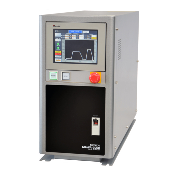
- Page 21 MAWA-300B Names of Parts (2) -1. Front panel The names of operating parts such as switches on the front panel are shown below. For the function of each part, refer to “3. (1) Front Panel.” Main power switch Touch panel display START button (with a green LED incorporated) RESET button (with an orange LED incorporated) Emergency stop button...
- Page 22 MAWA-300B (2) -2. Rear panel The names of terminals and connectors provided on the rear panel are shown below. For the cables to be connected to each part, refer to “2. (2) Connections.” (After the terminal cover is removed) Welding power supply input terminal block Input connector (D-Sub 37-pin, female) Output connector (D-Sub 25-pin, female) Optional input/output connector (D-Sub 25-pin, male)
- Page 23 MAWA-300B Specifications (3)-1. Product specifications MAWA-300B-00-00 MAWA-300B-00-01 Model name (Touch start) (High-voltage start) Power supply Three-phase 200 V AC ±10% (50/60 Hz) voltage Power consumption 13.2 kVA Maximum output 300 A current Secondary constant current control Control method Inverter type (Control frequency: approx. 45 kHz) Start type Touch start High-voltage start...
- Page 24 MAWA-300B Pre-flow 0 ~ 9999 ms (in unit of 1 ms) Initial current 0 ~ 999 ms (in unit of 1 ms) Up slope 0 ~ 99.9 ms (in units of 0.1 ms) Main welding WELD1 (*4) 100 ~ 999 ms (in unit of 1 ms) Down slope Time setting range Cooling (*4)
- Page 25 MAWA-300B Emergency Main power supply shut-off, welding current EM input circuit stop stop and starts prohibition Welding current stop Overcurrent Primary current protection detection Fuse: 50 A Internal Temperature temperature Welding current stop and start prohibition protection detection Start signal ON Start signal detection during Start prohibition...
- Page 26 MAWA-300B L1, L2, L3 and PE crimp-style terminals for Input terminal Torch (-): 3/8-24 UNF Output terminal Grounding (+): Φ8 (terminal thickness 5 mm) Terminal shape Gas connector One-touch joint: Φ8 External input connector D-Sub 37-pin (female), 2.6 mm screw External output connector D-Sub 25-pin (female), 2.6 mm screw *1: The duty cycle (load time for a period of 10 minutes) of “JIS C9300-1 3.37”...
- Page 27 MAWA-300B (3) -2. Product dimensions (3) -2-1. Main unit (Unit: mm) (3) -2-2. Panel unit (Unit: mm) 1. Overview...
- Page 28 MAWA-300B (3) -3. Duty cycle graph (Ambient temperature: 40°C) Duty cycle (%) * The duty cycle is the ratio (in percent) of load time for the total time. Duty cycle X (%) = (weld time of the 1st welding + the 2nd welding T ) / weld cycle T ×...
- Page 29 MAWA-300B Operational Principle Diagram Gate driver board 2 ゲートドライバ基板2 Thyristor サイリスタ Gate driver board 1 ゲートドライバ基板1 ダイオード Diode unit ユニット Inverter Thermal protector Breaker インバータ サーモプロテクト transformer EARTH(+) トランス Terminal Noise ノイズ Electromagnetic 電磁 Snub- block filter Snub- 端子台 ブレーカ フィルタ...
- Page 30 MAWA-300B Options The main options are shown in the table below. Product name Model Part No. PK-1173375-3m 1173375 Input cable (*1) PK-1173376-5m 1173376 10 m PK-1173377-10m 1173377 MB0909181-2 1159092 MB0909181-3 1159093 Grounding cable MB0909181-4 1159094 MB0909181-5 1159095 TA-23SSPC-2010-FL 1169585 Torch (with meshes) TA-23SSPC-3010-FL 1169586 φ1.6 (*2)
- Page 31 MAWA-300B 2. Installation and Connections WARNING When transporting the welding power supply with hands, hold the bottom surface. If the welding power supply is carried by holding such a projection as the terminal cover and the projection is damaged, causing the welding power supply to fall down, the foots may be collapsed by it.
- Page 32 MAWA-300B The installing conditions for the welding power supply are explained below. Take a serious view of the following contents. Ambient temperature +5 ~ +40°C Maximum humidity 85% or less (without condensation) Installing conditions Maximum altitude 1000 m or lower Pollution level Temperature range -10 ~ +55°C...
- Page 33 MAWA-300B Connections (2) -1. Preparation for connections The standard connection status is as shown in the following figure. Indicates accessories, indicates options. The input cable, grounding cable, torch, torch stand, touch start head, cooling water circulator and torch cable are options. For the information on options, make contact with us. (Refer to “1. (6) Accessories”...
- Page 34 MAWA-300B Products to be prepared by customer Pressure: 0.1 ~ 0.6 MPa Argon gas (cylinder type) Flow rate: 0.5 L/min or more <Reference> Manufacturer: YUTAKA Co., Ltd. Reducing valve and flow meter Product name: 2-step pressure adjuster with a flow meter Model: FR-II S-P <Recommended item>...
- Page 35 MAWA-300B (2) -2. Connecting the power supply WARNING Before connecting the primary power supply, turn off the source power supply on the factory side. Execute the grounding work (class D grounding or higher) for the primary power supply and PE terminal according to the electrode connection diagram. Unless Class D grounding work is executed, an electric shock may be caused by electric leakage or a high voltage may be cause by malfunction, resulting in an electric shock.
- Page 36 MAWA-300B In the following, how to connect the power supply will be described. Connect the input cable to the welding power supply input terminal block provided on the rear panel according to the following procedure. Turn off the source power supply on the factory side. Pass the input cable through the cable gland (lower) of the terminal cover.
- Page 37 MAWA-300B (2) -3. Connecting the ground WARNING Use the dedicated grounding cable. Fix the cable connecting part securely. Do not extend the cable more than the necessary length. The cable length should be 10 m or less. A large current will flow and a high voltage of about 10 kV will be applied at a start of welding.
- Page 38 MAWA-300B Fix the end of the grounding cable to the grounding terminal with the attached bolts and nuts. Remarks When tightening the nut, perform it so that the grounding cable may face toward the rear. Grounding terminal Bolt 2. Installation and Connections...
- Page 39 MAWA-300B (2) -4. Connecting the torch WARNING Use the dedicated torch cable. Fix the cable connecting part securely. Do not extend the cable more than the necessary length. The cable length should be 10 m or less. A large current will flow and a high voltage of about 10 kV will be applied at a start of welding.
- Page 40 MAWA-300B Turn the end of the torch cable and connect it to the torch terminal. Torch terminal Install the terminal cover on the rear panel. Put the claws on the left and right side into the grooves of the rear panel. Groove Claw Fix the terminal cover with the attached screws.
- Page 41 MAWA-300B Loosen the cap of the cable gland and clamp the cable. (2) -4-1. Improvement against an accidental fire Our torch: In order to improve the torch against an accidental fire (so that arc may not be scattered from the torch), we prepare a torch with a meshed nozzle and a nozzle ring.
- Page 42 MAWA-300B (2) -5. Connecting the argon gas WARNING Fix the gas cylinder securely on the cylinder stand or such a structure as the wall and pillar. If the gas cylinder is fallen down, the foot may be collapsed. Entrust the gas piping work with the specialist. If an inappropriate gas flow rate adjuster is used for the gas cylinder, the gas cylinder may be exploded.
- Page 43 MAWA-300B (2) -6. Connecting the external input/output devices In the following, how to connect the external input/output devices will be described. There are 4 connectors for external input/output on the rear panel. They are used for control from the outside and control of external devices.
- Page 44 MAWA-300B (2) -7. Connecting the external communication device In the following, how to connect the external communication device will be described. There is a connector for external communication on the rear panel. This connector is used to set conditions and read data from PC. For the connection with the external communication device, refer to “7.
- Page 45 MAWA-300B (2) -8. Connection with the torch head for touch start In the following, connections to be made for a touch start will be described. Make connections according to the following procedure. For the explanation and usage of the touch start function, refer to “5. (6)-2. Touch start.” Connection when the Torch drive type is set to “CYLINDER”...
- Page 46 MAWA-300B (2) -9. Removing the panel unit WARNING Before detaching and installing the panel unit, disconnect the input cable of the source power supply on the factory side of the welding power supply input. If the panel unit is detached with the input cable connected, an electric shock may occur.
- Page 47 MAWA-300B Remove the front cover and then remove four screws fixing the panel unit. Fixing screw Remove the gender changer connected between panel unit and connector of the main unit. Gender changer After re-placing the front cover, connect the input/output signal cable between the connector on the rear panel of the panel unit and the connector on the main unit, and tighten the connector-fixing screw.
- Page 48 MAWA-300B After installing the panel unit at a destination, connect the input cable of the source power supply on the factory side. To install the panel unit with M4 taps (4 positions) on both sides of the panel unit, prepare metal fittings, etc. The length of screw put into M4 tap is 10 mm or shorter. (Refer to “1.
- Page 49 MAWA-300B Interface (3) -1. Explanation of external input/output signals (3) -1-1. Input connector (D-Sub 37-pin, female) Remarks Every input terminal is a photo coupler input of +24 V DC/7 to 10 mA. Input signals Terminal Terminal name Explanation WELD STOP To stop the welding on the way, this terminal is closed.
- Page 50 MAWA-300B Terminal Terminal name Explanation User input terminal. For each terminal, the following settings can be selected. 01. GAS FLOW 02. H-ORG 03. H-HEAD UP (Refer to “2. (3)-3-1. User input terminals.”) Power supply for the gas flow rate sensor 0 V Power supply for the gas flow rate sensor 24 V EXT.COM Input terminal common.
- Page 51 MAWA-300B (3) -1-2. Output connector (D-Sub 25-pin, female) Remarks Output terminals are output by photo relay and the rating is +24 V DC/100 mA. Output signals Terminal Terminal Explanation name Welding OK signal. When the result is within the range of upper limit and lower limit of the GOOD monitor judging condition, this signal is turned on.
- Page 52 MAWA-300B (3) -1-3. Option input/output connector (D-Sub 25-pin, male) Remarks Every input terminal is a photo coupler input of +24 V DC/approx. 10 mA. Output terminals are output by photo relay and the rating is +24 V DC/100 mA. For the customer-prepared motor head, use this connector input/output. Refer to the timing chart in “6.
- Page 53 MAWA-300B *1: For the timing of the main welding start input (H-ST2) from the motor controller, refer to 6. (1), (2), (3), and (4) in the timing chart of the touch start. Only in “fine weld mode”, it is the timing from weld point (initial current) to head up.
- Page 54 MAWA-300B (3) -2. Connection diagram of external input/output signals (3) -2-1. Input connector (D-Sub 37-pin, female) Input signals I/O Input D-Sub 37(Female) 25) 24V(Flow sensor) INT.24V 36) INT.24V INT.24V EXT.COM 35) EXT.COM EXT.COM 24) 0V(Flow sensor) 37) COM EM RESET 13) EM RESET WELD STOP 1) WELD STOP...
- Page 55 MAWA-300B (3) -2-2. Output connector (D-Sub 25-pin, female) Output signals I/O Output D-Sub 25(Female) GOOD 1) GOOD 2) NG 3) END E.STOP 4) E.STOP ERROR 5) ERROR OUT5 7) OUT5 OUT4 8) OUT4 OUT3 9) OUT3 OUT2 10) OUT2 OUT1 11) OUT1 OUT_COM 6) OUT_COM...
- Page 56 MAWA-300B (3) -2-3. Option input/output connector (D-Sub 25-pin, male) Option input/output signals * When the internal power supply is used, connect terminal No.23 and terminal No.25. When the external power supply is used, connect 24 V DC to terminal No.23 and 0 V to terminal No.24.
- Page 57 MAWA-300B (3) -3. External input/output signal table (3) -3-1. User input terminals On the external input/output setting screen, input terminal Nos. 22 and 23 (IN1 and IN2) can be allocated from the following signals. (Refer to “4. (8) External I/O Setting Screen.”) Terminal name Explanation When the optional gas flow sensor is connected, “E25 GAS FLOW ERROR”...
- Page 58 MAWA-300B (3) -3-2. User output terminals On the external input/output setting screen, output terminal Nos. 7 ~ 11 (OUT 1 ~ OUT 5) and output terminal Nos. 15 and 16 (OUT 6 and OUT 7) can be allocated from the following signals. (Refer to “4.
- Page 59 MAWA-300B Terminal name Explanation When the measured current waveform of the second welding exceeds the 18.WEL2 UPPER upper limit of the judgment current value, this signal is output for the 02. NG CURRENT signal setting time. When the measured voltage value of the second welding is lower than the 19.WEL2 LOWER lower limit of the judgment voltage value, this signal is output for the 02.
- Page 60 MAWA-300B (3) -4. Input signal connecting method For connecting to the contact input device (when the internal power supply is used) Connect terminal No.35 and terminal No.36. Internal side External side INT.24V 36) INT.24V INT.24V EXT.COM 35) EXT.COM EXT.COM 37) COM WELD STOP 1) WELD STOP START...
- Page 61 MAWA-300B For connecting to the PNP open collector output device (when the external power supply is used) Connect the minus side of the external power supply of 24 V DC to terminal No.35. Internal side External side INT.24V 36) INT.24V INT.24V EXT.COM 35) EXT.COM...
- Page 62 MAWA-300B 3. Operating Unit Front Panel IMPORTANT Operate the switches and touch panel display carefully by hand. If they are operated violently or by using a screwdriver or pen point, this will result in damage. Operate each of the switches and touch panel display once a time. If multiple switches are operated at the same time, this will result in a failure.
- Page 63 MAWA-300B START button (with a green LED incorporated) This button LED lights (in green) when welding is ready. When the START key of the panel is made effective on the Switch select screen, welding is started by pressing this button while it lights.
- Page 64 MAWA-300B 4. Explanation of Screens Screen Structure The screen structure of MAWA-300B is as shown below. (4) 2 Envelope (2) 2 Password (4) 1 Envelope (3) Monitor screen Start-up screen setting screen input screen waveform check screen (2) 1 Menu screen (14) External I/O check screen (15) Count setting screen (16) Error history screen...
- Page 65 MAWA-300B Remarks Each of the switches provided in the upper right of each screen is used to go to the Menu screen or Monitor screen. Switch to go to the Monitor screen Switch to go to the Menu screen The switches provided in the left and right sides under the screen are used for a screen movement in the same category.
- Page 66 MAWA-300B Menu Screen Menu screen On the Menu screen, each function is displayed as a menu. The operator can go to the desired screen by pressing each switch. To display the Menu screen, press MENU provided in the upper right part of each screen. (a) Switch to go to the Monitor screen Used to go to the Monitor screen.
- Page 67 MAWA-300B Error History Used to go to the Error history screen. (k) Start mode display The currently selected start mode “Touch Start” or “HV. Start” is displayed. This is displayed in the upper part of each screen. Remarks When the password is made effective, the Password input screen is displayed by pressing the yellow switch.
- Page 68 MAWA-300B Monitor Screen To perform welding, display this screen. A welding result with the last welding condition No. is displayed. In the status where this screen is displayed, welding is enabled and the READY signal is output. To display the Monitor screen, press MONITOR in the upper right part of each screen. Then, you can go to another screen directly.
- Page 69 MAWA-300B (e) CURR The current waveform display (yellow lamp ON) or non-display (white lamp ON) can be selected. VOLT The voltage waveform display (red lamp ON) or non-display (white lamp ON) can be selected. (g) ZOOM The wave operating window for a waveform display change is opened. If this switch is pressed when the window is opened, the window can be closed.
- Page 70 MAWA-300B Remarks There is a difference in the waveform display range between when the “WELD1” and “WELD2” magnified display is selected and when “FULL” is selected. In the time display in the lower part of the graph, each weld time of “WELD1” and “WELD2” is displayed when the magnified display is selected.
- Page 71 MAWA-300B When the monitor value exceeds the upper limit value (Set value on the Upper/lower limit set screen in 4. (12)) When the monitor value is lower than the lower limit value (Set value on the Blue Upper/lower limit set screen in 4. (12)) VOLTAGE The monitor values of WELD1 and WELD2 welding voltages are displayed.
- Page 72 MAWA-300B screen are displayed. Even if the “Slope time” item of the Monitor select screen is set to “Exclude”, the waveform including the slope is displayed. Reference waveform While line Current waveform Yellow line Voltage waveform Red line * When the welding monitor value is “0”, no waveform is displayed. * When modulation is set, the modulation ON/OFF waveform is not displayed on the reference waveform.
- Page 73 MAWA-300B Envelope Screen To make the envelope function effective, turn on “ENVELOPE” in 4. (11) (d) of the Monitor select screen. In this screen, the current reference waveform/voltage reference waveforms are obtained for each condition No. and the upper/lower limit value from the reference waveform is set as waveform data.
- Page 74 MAWA-300B be selected. [Initial status: Not Display] UPDN The upper/lower limit waveform set on the Envelope setting screen is displayed in a dotted line. When CURR is made effective and UPDN is pressed, the upper/lower limit waveform of the current is displayed. When VOLT is made effective and UPDN is pressed, the upper/lower limit waveform of the voltage is displayed.
- Page 75 MAWA-300B When the monitor value is lower than the lower limit of envelope (Set value on 4. (4) Purple Envelope Screen) (k) SETTING The Envelop setting screen (Refer to 2 Envelope setting screen.) for setting the upper/lower limit value of envelope is displayed. Waveform display area After welding is performed on this screen, the welding waveform and the envelope waveform created from the upper/lower limit value set on the Envelope setting screen...
- Page 76 MAWA-300B Envelope setting screen This screen is used to decide and register the upper/lower limit value, reference waveform format, and envelope waveform to create an envelope waveform. (p) SCH The condition No. being set is displayed. (q) Current The upper limit value and lower limit value to be used for current envelope judgment can be set as relative values for the registered waveforms of the first welding (WELD1) and second welding (WELD2).
- Page 77 MAWA-300B However, the reference voltage waveform is only “Mes Value.” Env Wave regist Resistance welding is performed on the Envelope waveform check screen (Refer to “4. (4) 1 Envelope waveform check screen.”) and “Record” is pressed in the status where the envelope waveform is created, the envelope waveform data is saved into the condition No.
- Page 78 MAWA-300B Basic Setting Screen This screen is used to display and set the information on the welding power supply. (a) Type The type of the welding power supply is displayed. (b) Version The program version of the main unit control unit and the program version of the touch panel of MAWA-300B are displayed.
- Page 79 MAWA-300B (h) Comm speed A communication speed with external communication devices can be selected. 9600 Performs communication at 9600 bps. 14400 Performs communication at 14400 bps. 19600 Performs communication at 19600 bps. 38400 Performs communication at 38400 bps. [Initial value: 9600] Internal resistance It can be selected whether the resistor incorporated in MAWA-300B is used as a terminator for external communication.
- Page 80 MAWA-300B Switch Select Screen This screen is not used to set welding conditions for each schedule but is used to perform common detail settings. There 2 pages, namely, Switch select screen (1/2) and Switch select screen (2/2). Switch select screen (1/2) (a) NG judgment error It is possible to select whether when the monitor judgment results in “NG”, this is judged as an error status.
- Page 81 MAWA-300B At “ON”, the “START button” on the front panel is enabled. [Initial value: ON] (g) Internal Gas Flow This can select whether a gas flow operation is automatically controlled or not. At “ON”, the solenoid valve is turned on/off in conjunction with the weld time set on the Welding condition setting screen.
- Page 82 MAWA-300B Switch selection screen (2/2) (a) Torch drive type (Touch start only) Regarding the motive power to operate the torch, either “MOTOR” or “CYLINDER” can be selected. Perform this setting according to your torch. [Initial value: MOTOR] (b) GOOD/NG signal output time After the end of all the welding sequence, the GOOD/NG signal output time can be set.
- Page 83 MAWA-300B In Figure (A), since condition No. 1 and No. 8 are ON, welding is performed by condition No. 9. In Figure (B), since only condition No. 8 is ON, welding is performed by condition No. 8. Condition signals 16 and 32 are invalid because they are OFF at the decision of conditions. (e) SCH chg Delay time Sets the time to determine the SCH No.
- Page 84 MAWA-300B Initialize Memory Screen This screen is used to initialize the memory so that all the setting conditions of the welding power supply may be reset to the set values provided at delivery from the factory. This screen can be displayed by pressing “CLEAR”...
- Page 85 MAWA-300B Ext I/O Setting Screen Set inputs IN1/IN2 and outputs OUT1 ~ OUT7 of external input/output signals. Select them by “+” and “-.” The display is changed in the following order. User input terminals 01.GAS FLOW 02.H-ORG 03.H-HEAD UP User output terminals 01.GOOD 02.NG 03.END...
- Page 86 MAWA-300B Welding Condition Setting Screen This welding power supply permits setting up to 127 types of welding condition. In this screen, the welding condition No., weld time length, welding current magnitude, etc. are set. There are two setting screens, namely, FULL SETTING screen in which all the detail condition settings can be set by operator himself and SIMPLE SETTING screen in which conditions can be input easily.
- Page 87 MAWA-300B (b) Current Each peak current value at welding can be set independently. The settable range is 15 ~ 300 [A] (in unit of 1 [A]). For the details of each item, refer to the following table. WELD1 Initial current [Initial value: 15 A] (Touch start only) Up-slope initial current [Initial value: 15 A] Up-slope final current [Initial value: 15 A] Pulse current [Initial value: 15 A]...
- Page 88 MAWA-300B operated correctly. Only WELD2 setting cannot be performed. “E11 SET ERROR” will occur. Remarks If the value less than the effective digits for the time set value is input, it is rounded off when the screen is switched from the Welding condition setting screen to the Monitor screen to establish the set value.
- Page 89 MAWA-300B SIMPLE SETTING screen This screen permits settings easily because the number of current setting items is less than the FULL SETTING screen. When you go to the SIMPLE SETTING screen after setting conditions on the FULL SETTING screen and then display the Monitor screen, the set values of slope UL1 and DF1 of WELD1 automatically change into the same set current value of PL1 and the set values of slope UL2 and DF2 of WELD2 automatically change into the same set current value of PL2.
- Page 90 MAWA-300B (10) Schedule Setting Screen This screen is mainly used to set the pulse modulation of welding current. The welding current is determined by the data set in the welding condition settings and the data set on this screen. There are two types setting screens, namely, Schedule setting screen (1/2) to set the first welding and Schedule setting screen (2/2) to set the second welding.
- Page 91 MAWA-300B Modulation duty ratio = t/T x 100 [%] (e) Weld1 up/down pulse modulation ON/OFF Select whether to apply pulse modulation to the welding current in the UPS (up-slope) and DWS (down-slope) sections of the first welding. [Initial value: OFF] Waveform sample when the UPS/DWS pulse modulation is applied.
- Page 92 MAWA-300B Schedule setting screen (2/2) The currently selected condition No. is displayed. (k) Weld2 welding pulse modulation ON/OFF Select whether to apply the pulse modulation to the second welding current. [Initial value: OFF] Weld2 welding frequency [Hz] Set the modulation frequency of the second welding pulse. The setting range is 1 ~ 3000 [Hz].
- Page 93 MAWA-300B (11) Monitor Select Screen This screen is used to set the data to be obtained at welding and the data to make an upper/lower limit judgment. This setting can be performed for each condition No. (a) SCH The currently selected condition No. is displayed. (b) Monitor range Set a range to make an upper/lower limit judgment of monitor value.
- Page 94 MAWA-300B (c) Slope time Set whether to include the up-slope (UPS) section and down-slope (DWS) section in the upper/lower limit judgment. However, the upper/lower limit judgment of weld time is performed for the ranges of up-slope and down-slope. If “Exclude” is set, only the pulse current time (WEL) is displayed in the “TIME” item of the Monitor screen.
- Page 95 MAWA-300B (12) Upper/Lower Limit Set Screen This screen is used to set a threshold value for welding OK/NG judgment from the monitor value set to PEAK or RMS in 4. (6) (d) and (e). This setting can be performed for each condition No. An OK/NG judgment by waveform is performed on the Envelope setting screen.
- Page 96 MAWA-300B (13) SCH Copy Screen This screen is used to copy the condition setting data to an optional condition No. Copying can be performed for multiple condition numbers. The SCH copy screen is classified into 4 types, namely, 1 SCH copy screen, 2 Copy data check screen, 3 Copy start check screen, and 4 Copy in-process screen.
- Page 97 MAWA-300B Copy data check screen This screen is used to check the copy source data and copy destination data. It is possible to check the current, time and upper/lower limit value of an optional condition No. The condition No. of the displayed data is displayed. (g) WELD1 data display area The WELD1 (first welding) data is displayed.
- Page 98 MAWA-300B Copy start check screen This is the final check screen to start a condition copying. The condition copy is started. During the condition copy, the Copy in-process screen of 4 is displayed. After the copy is normally terminated, the SCH copy screen of 1 appears and the copy completion notice “Copy finish.”...
- Page 99 MAWA-300B (14) External I/O Check Screen This screen is used to check the external input/output signal status. In the case of an ON signal, the terminal No. portion lights. When the signal is OFF, the display lamp goes out. The input/output status screen is classified into the “I/O check” screen and the “I/O check (option)”...
- Page 100 MAWA-300B (c) Output signal operating switch Used to turn on/off output signals. Select a signal for selecting ON/OFF by “ ” and “ ” to select a “ON/OFF” status. (d) Screen feed switch The I/O check (OP) screen is displayed. (e) Screen return switch The I/O check (OP) screen reappears.
- Page 101 MAWA-300B (h) Output signal operating switch Used to turn on/off output signals. For details, refer to (c) Output signal operating switch of the I/O check screen of 1. Screen return switch The External I/O check screen reappears. Screen feed switch The External I/O check screen is displayed.
- Page 102 MAWA-300B (15) Count Setting Screen This screen is used to control and check the number of welding times and the amount of production. Each count value can be set and checked for each number. (a) SCH The condition No. being set is displayed. (b) Preset count/Total count Enabled when a value is input in “Preset.”...
- Page 103 MAWA-300B (16) Error History Screen This screen is used to check the errors that were caused in the past. The number of errors that can be stored is 120. The older errors exceeding this number will be deleted in order for updating. (a) SCH The condition No.
- Page 104 MAWA-300B (17) Password Setting Screen In this welding power supply, it can be protected to go to a specific setting screen by entering a password. The following screen is used to set a password and select the validity/invalidity of the password.
- Page 105 MAWA-300B (18) Maintenance Screen Display this screen to perform maintenance of the welding power supply. To make a gas flow rate check, the gas can be turned on and off by manual operation. To check the sequence operation without causing the welding current to flow, it can be set that the welding current output is turned on/off.
- Page 106 MAWA-300B (19) Set Values of Each Screen at Delivery from the Factory The following table shows initial set values of each screen at delivery from the factory. When the memory was initialized on the Switch select screen, these initial values are provided. Screen Parameter Initial value...
- Page 107 MAWA-300B Screen Parameter Initial value SCH No. (condition No.) SCH TYPE CHG (condition setting mode) FULL FST (current value) (*1) 15.00 [A] UF1 (current value) 15.00 [A] UL1 (current value) 15.00 [A] PL1 (current value) 15.00 [A] DF1 (current value) 15.00 [A] DL1 (current value) 15.00 [A]...
- Page 108 MAWA-300B Screen Parameter Initial value Monitor value measuring range WELD1+WELD2 Slope time Exclude Monitor select Current value screen (all of condition Nos. Voltage value Upper/lower limit judgment 1 ~ 127) output Weld time Envelope WELD1 360 [A] Upper limit value WELD2 360 [A] Current value...
- Page 109 MAWA-300B 5. Welding WARNING Do not measure the voltage by connecting a general voltmeter or oscilloscope to the output terminal or between torch and base material. A high voltage of the start circuit is applied to the output terminal. The measuring person may receive an electric shock or the measuring apparatus may be damaged.
- Page 110 MAWA-300B Turning on the Power Supply Turning on the power supply will be described below. 1. Turn on the source power supply on the factory side. 2. Turn ON (to the “I” side) the “Main power switch” on the front panel. The start-up screen is displayed and then the Monitor screen is displayed on the touch panel display.
- Page 111 MAWA-300B Basic Function Setting The basic function setting of the welding power supply will be described below. Set the following basic setting items of the welding power supply on the Basic setting screen. Device No. Communication type and communication speed Display language selection Screen brightness Displaying the Basic setting screen...
- Page 112 MAWA-300B (3) -1. Common detail item setting The detail setting of the welding power supply functions will be described below. Set the detail items that are common to each welding condition on the Switch select screen. Remarks The Switch select screen consists of 2 pages. Displaying the Switch select screen 1.
- Page 113 MAWA-300B Welding Condition Setting (4) -1. Registering the welding conditions Registering the welding conditions will be described below. In MAWA-300B, up to 127 types of the welding condition can be registered. Register the welding conditions on the Welding conditions setting screen. Remarks The welding condition setting screen consists of 2 types.
- Page 114 MAWA-300B (4) -2. Welding current pulse modulation setting The welding current pulse modulation setting will be described below. Perform this welding current pulse modulation setting on the Schedule setting screen. Remarks The welding current is determined from the set data on the Welding condition setting screen and the set data on the Schedule setting screen.
- Page 115 MAWA-300B (4) -3. Welding condition copy Copying the welding conditions will be described below. The contents of the welding condition setting can be copied into the welding conditions of different condition Nos. Copy the welding conditions on the SCH copy screen. Displaying the SCH copy screen 1.
- Page 116 MAWA-300B Monitor Function Setting (5) -1. Monitor item setting The monitor item setting is described below. MAWA-300B judges whether the welding is OK or NG from the monitor value and the set upper/lower limit value. Set the upper/lower limit judging range and target items for the OK/NG judgment on the Monitor select screen.
- Page 117 MAWA-300B (5) -2. Upper/lower limit value setting The upper/lower limit value setting will be described below. Set the upper/lower limit value to be used for a welding OK/NG judgment on the Upper/lower limit set screen. Remarks For the upper/lower limit value setting to be used for OK/NG judgment using the envelope waveform, refer to “4.
- Page 118 MAWA-300B Touch Start (6) -1. Overview The touch start function of this welding power supply is used to perform arc welding by causing the initial current to flow in the status where the electrode is in contact with a workpiece and keeping the distance from the arc discharge gap.
- Page 119 MAWA-300B (6)-2-1. Normal mode operation The normal mode is applied when the initial current time FST (ms) on the Welding condition setting screen is set to 1 to 200 (ms). Touch start head Electrode touch Electrode touch sensor (OFF) sensor (ON) Torch follow-up Main Initial...
- Page 120 MAWA-300B (6)-2-2. Auto mode operation The auto mode is applied when the initial current time FST (ms) on the Welding condition setting screen is set to 0 (ms) and the Fine Weld Mode on the Switch select screen (1/2) is set to “OFF.” Touch start head Electrode touch Electrode touch...
- Page 121 MAWA-300B (6)-2-3. Fine weld operation The fine weld mode is applied when the initial current time FST (ms) on the Welding condition setting screen is set to 0 (ms) and the Fine Weld Mode on the Switch select screen (1/2) is set to “ON.” Touch start head Electrode touch Electrode touch...
- Page 122 MAWA-300B (6) -3. Adjustment After a start, the head goes down outputting gas for the pre-flow time. After the end of the pre-flow time, the head goes up outputting the initial current for the initial current time. After the end of the initial current time, welding is started.
- Page 123 MAWA-300B Preparation for Starting Welding The preparation to be made before a start of welding will be described below. To perform welding, display the Monitor screen on the touch panel display. Remarks When the Monitor screen is displayed, welding is enabled and the READY signal is output. Displaying the Monitor screen 1.
- Page 124 MAWA-300B Checking and Registering the Envelope Waveform Data Checking and registering the envelope waveform data will be described below. The Envelope screen is displayed by pressing ENVEL on the Monitor screen. On the Envelope screen, the envelope waveform created from the resistance waveform and upper/lower limit value can be checked and also the envelope waveform can be registered.
- Page 125 MAWA-300B Shutting off the Power Supply Shutting off the power supply will be described below. Set the “Main power switch” on the front panel to “OFF.” The power supply is shut off. Turn off the source power supply on the factory side. 5.
- Page 126 MAWA-300B 6. Timing Chart Touch Start (servo motor type welding head) The following is a timing chart for the case where the touch start head (MH-109TA) is used. サーボモータ式溶接ヘッド MH-TL01A Touch start head MH-109TA フットSW 1ST Footswitch 1ST Initial current start input (*1) 初期電流開始入力...
- Page 127 MAWA-300B Touch Start (when the customer-prepared motor head is used) The following is a timing chart example for the case where the touch start head (customer-prepared product) is used. Motor head (customer-prepared product) モータヘッド(お客様準備品)動作例 ※1 Torch head moving トーチヘッド 始点 operation Start 移動動作...
- Page 128 MAWA-300B Touch Start (when the auto mode is set) Touch start head unit MH-109TA Footswitch Input: 1ST Footswitch Input: 2ND Servo head Start point Moving Weld point (main welding) operation Middle point Weld point (initial current) Initial current start signal Output: ST1 (= H-ST1) Main welding start signal Output: ST2 (= H-ST2)
- Page 129 MAWA-300B Touch Start (when the fine weld mode is set) Touch start head unit MH-109TA Footswitch Input: 1ST (9pin) Footswitch Input: 2ND (10pin) Servo head Start point Moving Weld point (main welding) operation Middle point Weld point (initial current) Initial current start signal Output: ST1 (= H-ST1) Main welding start signal Output: ST2 (= H-ST2)
- Page 130 MAWA-300B Touch Start (at occurrence of LOST) The following is a timing chart for the case where the arc stops in the process of welding. Torch head start point トーチヘッド 始点 Moving operation 移動動作 Weld point (main welding) 溶接点(本通電) 溶接点(初期電流) Weld point (initial current) H-ST1 H-ST1...
- Page 131 MAWA-300B Touch Start (air type welding head) The following is a timing chart for the case where the air type welding head is used. 1~200ms ※1 START input START入力 READY output READY出力 ※5 ※2 SYNC OUT SYNC OUT output 出力 PURGE PURGE Gas start input...
- Page 132 MAWA-300B Touch Start Option Input/Output Signals The following is a timing chart for option input/output signals (H-ORG and H-HEAD UP). H-ORG input H-ORG 入力 H-ORG output H-ORG 出力 H-READY input H-READY入力 SYNC OUT output SYNC.OUT出力 welding in process 通電中 H-HEAD UP input H-HEAD UP 入力...
- Page 133 MAWA-300B The following a timing chart for option input/output signals (M-READY, H-STOP and H-RESET). READY output READY出力 通電開始可能状態 welding start enable status M-READY output M-READY 出力 Emergency stop 非常停止 H-STOP output H-STOP 出力 RESET input RESET 入力 H-RESET output H-RESET 出力 H-ERROR input H-ERROR入力...
- Page 134 MAWA-300B High-voltage Start The following is a timing chart at a high-voltage start. 1 When there is no retry and the arc welding is successfully done START input START入力 1~200ms ※1 ※5 READY output READY出力 ※2 Gas output ガス出力 Pre-flow After-flow プリフロー...
- Page 135 MAWA-300B 2 When the retry number is 2 and the arc welding is successfully done START input START入力 1~200ms ※1 ※5 READY output READY出力 Approx. 30 ms ※2 Gas output ガス出力 Pre-flow After-flow プリフロー アフターフロー set time set time 設定時間 設定時間...
- Page 136 MAWA-300B High-voltage Start (at occurrence of LOST) The following is a timing chart for the case where an accidental fire occurs at a high-voltage start. 1 When the arc stops in the process of welding START input START入力 1~200ms ※1 READY output READY出力...
- Page 137 MAWA-300B 2 When the retry number is 2 and the arc welding is not done START input START入力 1~200ms ※1 READY output READY出力 ※2 Gas output ガス出力 Pre-flow プリフロー 設定時間 set time SYNC OUT SYNC.OUT出力 output Approx. Approx. 130 ms Approx.
- Page 138 MAWA-300B (10) Schedule Changeover The following is a timing chart for the case where the schedule is changed over. SCH1 input SCH1入力 SCH2 input SCH2入力 SCH4 input SCH4入力 SCH8 input SCH8入力 PARITY input PARITY入力 SCH1 welding SCH2 welding SCH3 welding SCH4 welding SCH1通電...
- Page 139 MAWA-300B (11) Schedule No. and SCH Select Terminals ○: Closed Blank: Open Signal name SCH1 SCH2 SCH4 SCH8 SCH16 SCH32 SCH64 PARITY SCH No ○ ○ ○ ○ ○ ○ ○ ○ ○ ○ ○ ○ ○ ○ ○ ○ ○...
- Page 140 MAWA-300B Signal name SCH1 SCH2 SCH4 SCH8 SCH16 SCH32 SCH64 PARITY SCH No ○ ○ ○ ○ ○ ○ ○ ○ ○ ○ ○ ○ ○ ○ ○ ○ ○ ○ ○ ○ ○ ○ ○ ○ ○ ○ ○ ○...
- Page 141 MAWA-300B Signal name SCH1 SCH2 SCH4 SCH8 SCH16 SCH32 SCH64 PARITY SCH No ○ ○ ○ ○ ○ ○ ○ ○ ○ ○ ○ ○ ○ ○ ○ ○ ○ ○ ○ ○ ○ ○ ○ ○ ○ ○ ○ ○...
- Page 142 MAWA-300B Signal name SCH1 SCH2 SCH4 SCH8 SCH16 SCH32 SCH64 PARITY SCH No ○ ○ ○ ○ ○ ○ ○ ○ ○ ○ ○ ○ ○ ○ ○ ○ ○ ○ ○ ○ ○ ○ ○ ○ ○ ○ ○ ○...
- Page 143 MAWA-300B 7. External Communication Function Overview If the communication connector (D-Sub 9-pin, female) on the rear panel is used, conditions can be set and monitor data and various statuses can be read out from an externally connected PC. Explanation of communication connector (D-Sub 9-pin, female) signals RS-485 Terminal name Explanation...
- Page 144 MAWA-300B Configuration For connecting only one unit Internal resistance: ON Host computer ホストコンピュータ 内部抵抗:ON 装置No.01 Device No.01 RS232C RS485 RS232C/485変換アダプタ RS232C/485 conversion adapter For connecting multiple units Internal Internal Internal resistance: ON resistance: OFF resistance: ON Host computer ホストコンピュータ 内部抵抗:OFF 内部抵抗:OFF 内部抵抗:ON 装置No.01...
- Page 145 MAWA-300B Protocol One-way communication mode (1) Monitor data (Monitor data is transmitted at each end of communication.) Data strings !01 001 S10:01, 01, 015.0, 01.00, 111.0, 020.0, 02.00, 222.2, 100000, 111111, C D E 22222, 222 [CR][LF] Device No. Fixed 2 digits of 01 ~ 31 Condition No.
- Page 146 MAWA-300B (2) Error data Data strings !01 001 S07:E03,04, 12, 15, 17, 19, 22, 24 [CR][LF] D E F G H I Device No. Fixed 2 digits of 01 ~ 31 Condition No. Fixed 3 digits of 001 ~ 127 Command No.
- Page 147 Code: # Device No. R Condition No. S Command No. * Example: Every error data that occurred is read by the specified device No.01. Host side 0 1 * * * 0 7 : E18,E19 AMADA 0 0 0 MIYACHI Data product At reading, condition No.
- Page 148 Example: All the contents of data specified by command “01” of device No. “008” of the specified device No.01 are read. Host side 0 1 0 0 8 0 1 : AMADA 0 0 8 MIYACHI Data product At reading, condition No. for SH1, SH2 and SH3.
- Page 149 MAWA-300B Data Code Table 1-1 Command 01 (condition data) Data for each condition No. (Condition No.: 001 ~ 127) [Touch start setting] Character Item Contents Range string Torch No. 01: TORCH 1 01: FULL setting mode Condition setting mode 02: SIMPLE setting mode Initial current value WELD1 up-slope initial current WELD1 up-slope final current...
- Page 150 MAWA-300B Character Item Contents Range string WELD2 modulation duty ratio nnn, 10 ~ 90 (%) WELD2 slope section modulation 0: OFF 1: ON ON/OFF WELD2 base current value 015 ~ 300 (A) (in unit of 1 A) 1-2 Command 01 (condition data) Data for each condition No. (Condition No.: 001 ~ 127) [High-voltage start setting] Character Item...
- Page 151 MAWA-300B Character Item Contents Range string WELD1 slope section modulation 0: OFF 1: ON ON/OFF WELD1 base current value nnn, 015 ~ 300 (A) (in unit of 1 A) Number of retries 0 ~ 5 WELD2 pulse modulation ON/OFF 0: OFF 1: ON WELD2 modulation frequency nnnn, 0001 ~ 3000 (Hz)
- Page 152 MAWA-300B Character Item Contents Range string Voltage value upper/lower limit judgment output 0: OFF 1: ON Weld time upper/lower limit judgment output 0: OFF 1: ON Envelope upper/lower limit judgment output 0: OFF 1: ON Command 04 (envelope data) Data for each condition No. (Condition No.: 001 ~ 127) Character Item Contents...
- Page 153 MAWA-300B 6-1 Command 06 (basic setting data) Common data (Condition No.: fixed to 000) [Touch start setting] Character Item Contents Range string 1 (*1) Power supply model nnnnnnnnn, MAWA-300B 2 (*1) CPU software version nnnnnnn, V**-*** 3 (*1) GP panel software version nnnnnnn, V**-*** 1: Touch start...
- Page 154 MAWA-300B Character Item Contents Range string H-HEAD UP nnn, 001 ~ 200 (ms) 00: No input setting User input terminal 1 01: GAS FLOW 02: H-ORG User input terminal 2 03: H-HEAD UP 00: No output setting 01: GOOD 02: NG 03: END User output terminal 1 04: ERROR 05: READY 06: LOST...
- Page 155 MAWA-300B 6-2 Command 06 (basic setting data) Common data (Condition No.: fixed to 000) [High-voltage start setting] Character Item Contents Range string 1 (*1) Power supply model nnnnnnnnn, MAWA-300B 2 (*1) CPU software version nnnnnnn, V**-*** 3 (*1) GP panel software version nnnnnnn, V**-*** 1: Touch start...
- Page 156 MAWA-300B Character Item Contents Range string 00: No output setting 01: GOOD 02: NG 03: END User output terminal 1 04: ERROR 05: READY 06: LOST 07: WEL1 LOWER CURRENT 08: WEL1 UPPER CURRENT User output terminal 2 09: WEL1 LOWER VOLTAGE 10: WEL1 UPPER VOLTAGE 11: WEL1 LOWER TIME 12: WEL1 UPPER TIME...
- Page 157 MAWA-300B Command 07 (error data) Common data (Condition No.: 000) Error data check (data reading only: MAWA-300B → Host computer) Character Item Contents Range string Error code 1 nnn, E01 ~ E28 Error code 2 01 ~ 28 Error code 3 01 ~ 28 Error code 4 01 ~ 28...
- Page 158 MAWA-300B Command 10 (welding result) Common data (Condition No.: 000) Welding result check (data reading only: MAWA-300B → Host computer) Welding result data by the latest welding conditions is read. Character Item Contents Range string Welding result 01: GOOD 02: NG 03: LOST WELD1 current nnn.n, 000.0 ~ 999.9 (A)
- Page 159 MAWA-300B Command 11 (current waveform data check) Common data (Condition No.: 000) Resistance welding current waveform check (data reading only: MAWA-300B → Host computer) Up to 202 points of current waveform data are transmitted with line feeds. (Line feeds are not inserted after Average interval of acquisition and Number of monitor display waveform data.) Character Item...
- Page 160 MAWA-300B ⑪ Command 13 (current waveform data acquisition) Common data (Condition No.: 000) Resistance welding current check (data reading only: MAWA-300B → Host computer) Up to 6002 points of current waveform data are transmitted with line feeds. (Line feeds are not inserted after Interval of acquisition and Number of waveform data.) Character Item...
- Page 161 MAWA-300B 8. Troubleshooting Error Screen When an error occurs in the welding power supply, the Error screen will be displayed on the touch panel display. The error code, error message, condition No. at occurrence of the error, and error occurrence time after turning on the welding power supply are displayed. After removing the cause of the error, press the “RESET”...
- Page 162 MAWA-300B Error Messages Error Error Time of Cause Corrective measure code message detection Check the emergency stop input. * The emergency stop error will be cleared in 6 seconds EMER- The emergency stop signal was after pressing the RESET GENCY At all times input.
- Page 163 MAWA-300B Error Error Time of Cause Corrective measure code message detection If this error occurs after a The welding power supply was At all times restart, repairing is required. faulty. ERROR Make contact with us. CURRENT Execute maintenance for The measured welding current was Immediately LIMIT the electrode and...
- Page 164 MAWA-300B Error Error Time of Cause Corrective measure code message detection The data reading/writing from If this error occurs after a FeRAM FeRAM was not terminated At all times restart, repairing is required. ERROR normally. Make contact with us. Check whether the “Emergency stop”...
- Page 165 MAWA-300B Error other than Above If the buzzer of the main unit sounds continuously as “bleep, bleep, bleep”, make contact with The START MODE CHECK screen is for checking the arc start type. The START MODE CHECK screen is displayed after the main power switch is turned ON, make contact with us.
- Page 166 MAWA-300B 9. Maintenance WARNING For maintenance inspection and cleaning, stop the electric supply and turn off the power supply on the factory side except the case where no electric power is required. Put a notice of “Under inspecting operation” for other workers. If the charging part is touched carelessly, this may result in an electric shock.
- Page 167 MAWA-300B Press “Maintenance” on the Menu screen. The Maintenance screen is displayed. Press “PURGE OFF” on the Maintenance screen. “PURGE ON” is displayed and argon gas flows for about 15 seconds. After the argon gas flow is stopped, “PURGE OFF” is automatically displayed again. If the flow rate is insufficient, check the argon gas pressure and the residual quantity.
- Page 168 MAWA-300B Periodic Maintenance (2) -1. Monthly maintenance (2) -1-1. Cleaning the cooling fan filter IMPORTANT When the filter used in the cooling fan of the rear panel is dirty, the air flow will be deteriorated and the internal temperature of the welding power supply will go up, thereby causing a failure. How to clean the cooling fan filter will be described below.
Need help?
Do you have a question about the PULSETIG MAWA-300B Series and is the answer not in the manual?
Questions and answers