Advertisement
Quick Links
Advertisement

Related Manuals for Amada IS-300A


Summary of Contents for Amada IS-300A
- Page 1 Original instructions DC INVERTER WELDING POWER SUPPLY IS-300A OPERATION MANUAL AA01OM1182868-13...
- Page 2 IS-300A Thank you for purchasing our DC Inverter Welding Power Supply IS-300A. This operation manual describes its method of operation and precautions for use. Read this operation manual carefully prior to use. Store appropriately for ready reference. Contents Special Precautions ......................1-1 (1) Safety Precautions.......................
- Page 3 IS-300A Timing Chart ........................8-1 (1) Basic Sequence ......................8-1 (2) Detailed Description of Welding Current and Sequence in the Event of an Error ..8-3 (3) Sequence at PULSATION Setting ................8-5 External Communication Function ................9-1 (1) Introduction ........................9-1 (2) Data Transmission .......................
- Page 4 IS-300A 1. Special Precautions (1) Safety Precautions Before using, read "Safety Precautions" carefully to understand the correct method of use. • These precautions are shown for safe use of our products and for prevention of damage or injury to operators or others. Be sure to read each of them, since all of them are important for safety.
- Page 5 IS-300A WARNING Do not insert your fingers or hands between the electrodes. When welding, keep your fingers and hands away from the electrodes. Do not touch any welded part or electrode during welding or just after completion of welding. The welded parts of a workpiece, electrodes, and the arm are very hot.
- Page 6 IS-300A CAUTION Apply the specified supply voltage. Application of a voltage outside the specified range may result in fire or electric shock. Do not allow water to come in contact with the equipment. Water on the electric parts can cause electric shock and short circuit.
- Page 7 IS-300A (2) Precautions for Handling When transporting or moving the Power Supply, do not lay it down. Also, handle the Power Supply with care so as not to make an impact such as drop on it. Install this Power Supply on a firm and level surface. If it is inclined, malfunction may result.
- Page 8 IS-300A (3) On Disposal This product incorporates parts containing gallium arsenide (GaAs). At the time of disposal, separate it from general industrial waste or domestic waste and carry out the disposal in accordance with applicable laws and regulations. (4) Warning Labels for Safety On the main body are warning labels for safety.
- Page 9 IS-300A Location: Input breaker cover DANGER Meaning: Shock hazard, Cautions for high voltage HIGH VOLTAGE 1. Special Precautions...
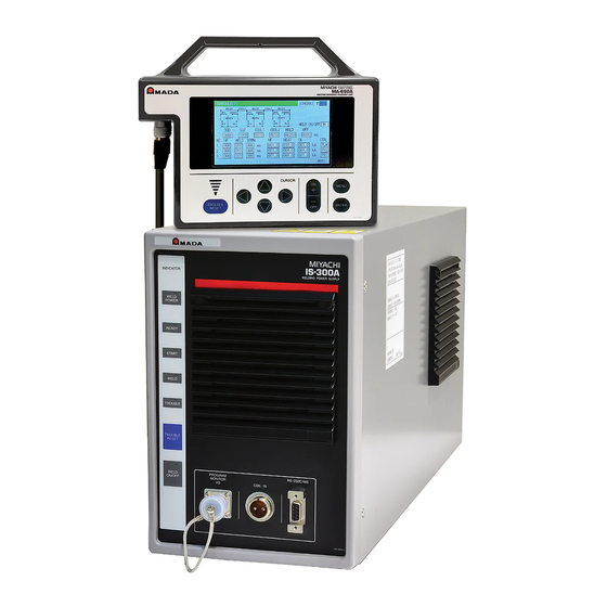
- Page 10 IS-300A 2. Features The FINE SPOT-INVERTER IS-300A is an inverter-type power supply, specially designed to be used for spot welding and fusing. In addition, it is small in size and convenient to move or shift. Monitor function is provided, which enables judging defective or non-defective welding.
- Page 11 ○ WELD POWER lamp (green LED) Lights up when the power is supplied to IS-300A. READY lamp (green LED) Lights up when the system is ready to start welding. To turn on this lamp: • WELD ON/OFF key •...
- Page 12 TROUBLE lamp (orange LED) Lights up when trouble is detected. At this time, the program unit makes a peeping sound, and the work done by IS-300A is interrupted. TROUBLE RESET key If this key is pressed while the TROUBLE lamp is lit, that lamp is turned off.
- Page 13 IS-300A (2) Rear Input breaker cover Input terminal cover Output terminal cover Terminal covers mounted Terminal covers removed Connecting terminal strip for external input/output signal Used to input the schedule signals and output trouble signals.
- Page 14 TROUBLE RESET key If this key is pressed while the TROUBLE lamp of IS-300A is lit, the lamp goes off. It has the same function as the TROUBLE RESET key of IS-300A. CURSOR keys Used to move the cursor ( ) to select an item.
- Page 15 Connector Used to connect the circuit cable. Connect the other end of the cable to the PROGRAM MONITOR I/O connector of IS-300A. CAUTION No settings or changes may be made to any item from the receipt of the start signal through the end of the welding sequence and turning off the start signal.
- Page 16 IS-300A 4. How to Operate Screens ATTENTION The Power Supply writes data into the flash memory on the control board when a setting is changed or a schedule data is copied. The READY lamp on the front panel and the external READY signal are turned off during writing. Check that the READY lamp is turned on to start welding.
- Page 17 Select the language among Japanese, English, Chinese, and Korean. (f) MA-660A PROGRAM VERSION Indicates the program version No. of Program Unit MA-660A. (g) MA-660A ( IS-300A ) PROGRAM VERSION Indicates the program version No. of the Power Supply’s screen display part. (h) IS-300A PROGRAM VERSION Indicates the program version No.
- Page 18 IS-300A (3) SCHEDULE Screen Up to 255 welding schedules can be set on the Power Supply. In the SCHEDULE screen, there are Current and time setting screen and Pulsation and transformer screen. Current and time setting screen This screen is used to set the SCHEDULE No., length of weld time, welding...
- Page 19 IS-300A * OFF/Off time ・ Count and step value are updated each welding. ・ RE-WELD does not work simultaneously with OFF/Off time. When OFF/Off time is set, RE-WELD becomes invalid. ・ START SIGNAL MODE has limitations. When OFF/Off time is set, MAINTAINED of START SIGNAL MODE does not work.
- Page 20 IS-300A When the downslope time is set for the previous stage in the multi-stage welding. The downslope time is set for the previous stage, and the DL HEAT setting of E and the HEAT setting of F are different.
- Page 21 IS-300A (Note) Upslope / Downslope waveform when INTERVAL (downtime) is set to 0. E-10 (Schedule setting error) will occur when the Power Supply starts with the following setting. When the upslope time is set in the pulsation welding. The upslope time is set, and the UF HEAT setting of C and the HEAT setting of D are different.
- Page 22 IS-300A When the upslope time and the downslope times are set in the pulsation welding. The upslope time and the downslope time are set, and the UF HEAT setting of D and the DL HEAT setting of F are different.
- Page 23 IS-300A (Note) Control method of the inverter-type welding power supply Control Feature Application Control mechanism method Detects the primary current by Requires no connection Used for welding in the current sensor mounted of toroidal coil on the a robot or an...
- Page 24 IS-300A Control Feature Application Control mechanism method Used for special Constant-phase Welding with the fixed cases such as the control Controls switching with the set pulse width. No feedback test of welder, and (Non-constant pulse width. control. not used for normal current) welding.
- Page 25 IS-300A (a) SCHEDULE # Select from #001 to #255 to set the SCHEDULE. Normally select #001 first, then select additional schedules in sequential order. (b) PULSE LIMIT When limiting the pulse width in Primary constant-current peak value control, set the limit for each of WELD1, WELD2 and WELD3.
- Page 26 IS-300A a caution signal is output after completion of welding. (See (5) MONITOR SET Screen.) (d) WELD TRANS FREQ Sets the frequency of the welding transformer to be used. It can be set 600 Hz to 3000 Hz in units of 100 Hz.
- Page 27 IS-300A (j) GAIN Sets the amount of feedback correction in the primary constant-current effective value control, secondary constant-current effective value control, secondary constant-power effective value control, and secondary constant-voltage effective value control. Though 1 is normally used, the larger value will give the shorter rise time.
- Page 28 IS-300A (4) MONITOR Screen In this screen, you can confirm the operational conditions during welding. Monitored data is displayed for each SCHEDULE. (a) SCHEDULE # Set the No. of the SCHEDULE to monitor. The measured values (welding current, voltage, etc.) for welding within that SCHEDULE are displayed.
- Page 29 IS-300A (g) STEP # The present number of steps is displayed when STEPPER MODE (see (9)(k)) is not OFF on the MODE SELECT screen. (In the example above, the VALVE 1 is set to STEP 1, the VALVE 2; STEP 3.)
- Page 30 IS-300A When WELD2 STOP/WELD COUNT is WELD2 STOP and COUNTER is WORK WELD COUNTER and WORK COUNTER are displayed. When the count reaches the set WELD count value, WORK count value is incremented by one. This is different from WELD COUNTER described in in meaning.
- Page 31 IS-300A (5) MONITOR SET Screen Set the conditions for determining a good or bad weld, including values for welding current, upper or lower limits for the secondary voltage, etc. If the monitored welding current, secondary voltage, etc., do not meet the set conditions, a caution signal is output, and can be used to activate an alarm buzzer, alarm lamp, or similar event.
- Page 32 IS-300A (Note) Upper/Lower limit judgment value when STEPPER MODE is not OFF The upper/lower limit judgment value set here is for the current when a welding is performed, not for the initial setting. Therefore, when STEPPER MODE is not OFF to perform step-up (-down) for the initial setting, the upper/lower limit judgment value is stepped up or down automatically.
- Page 33 IS-300A (6) NG SIGNAL SELECT Screen Sets the output mode and the signal for each item to output, ERROR or CAUTION, in an error occurring. (This screen shows initial settings.) (a) ERROR OUTPUT MODE Sets the output modes of NG1 and NG2 of the external output signals. (Refer to 6.
- Page 34 IS-300A (Note) Receiving the start signal after error output and Continuous welding operation Start signal after error Continuous welding output with off time (OFF) ERROR Not receive Stop Upper/lower limit monitor error CAUTION Receive Not stop ERROR Not receive Stop...
- Page 35 IS-300A (7) OUTPUT SELECT Screen Sets the output signals OUT1 (Pin 28) to OUT5 (Pin 32) of the external output signals. For the contents of each output signal, refer to 6.(3). (This screen shows initial settings.) Pressing +ON key switches the signal in the following order (in the reverse direction when pressing -OFF key): END (end signal) →...
- Page 36 For how to perform a schedule copy, see the next page. The schedule copy can be performed between IS-300As with the same program version of MA-660A (IS-300A). The program version of MA-660A (IS-300A) is displayed on the POWER SUPPLY STATE screen. (See (2)(g).) 4.
- Page 37 (b) IS-300A <----- MA-660A The data in memory of MA-660A is copied to IS-300A. Perform this operation on the source IS-300A and then perform it on destination IS-300A. After copy is complete (<END> display), wait for about 10 seconds to turn off IS-300A.
- Page 38 IS-300A (9) MODE SELECT Screen (a) DELAY START SET One welding condition is determined via DELAY START SET, a value corresponding to chatter prevention time, after a start signal is input. The DELAY START SET period can be set in a range from 1 to 20 ms, in unit of 1 ms.
- Page 39 IS-300A (Note) When DELAY START SET is 1 ms or 2 ms The schedule number when the 2ND STAGE signal is received is selected. Therefore, in Fig. (A) above, the schedule number is not selected and the schedule signal input error occurs. When DELAY START SET is 1 ms or 2 ms, input the schedule signal in advance before the 2ND STAGE signal is received.
- Page 40 In 4) to 7) below, schedule signals double as start signals. IS-120B has this function, and it can be used when replaced with IS-300A. The signal after the time of DELAY START SET from the first input schedule signal is determined.
- Page 41 IS-300A In 4) and 5), up to 255 schedules can be used by combining schedule signals SCH1/2/4/8/16/32/64/128 in binary. In Fig. B: Binary start, schedule No. 13 is selected since signals SCH1/4/8 are determined. In 6) and 7), a schedule of the smallest number among input schedule signals SCH1/2/4/8/16/32/64/128 can be used.
- Page 42 IS-300A * There is no distinction between ERROR and CAUTION. END signal output Count-related Upper/lower Other errors Stopped halfway SIGNAL Normal error limit error at welding (MAINTAINED) MODE Output Output Output No output No output Output Output No output No output...
- Page 43 IS-300A Note 1: Schedule Nos. and Schedule Selection Pins ●: Closed Blank: Open SCHEDULE# SCH 1 SCH 2 SCH 4 SCH 8 SCH16 SCH32 SCH64 SCH128 PARITY ● ● ● ● ● ● ● ● ● ● ● ● ●...
- Page 44 IS-300A Note 2: Current shutoff function The current shutoff function shuts off current when the proper weld penetration is achieved—for example, during fusing—thus preventing excessive penetration. (Refer to figure below.) With the Power Supply connected our weld checker, set the displacement in advance.
- Page 45 IS-300A The WE3 STOP signal shuts off current immediately when input during the WE3 period, switching the sequence to HOLD. The WE3 STOP signal shuts off current immediately after the WE3 starts (the current is supplied for about 1 cycle) when input before the WE3 period, switching the sequence to HOLD.
- Page 46 IS-300A (i) FLOW SWITCH/PRG PROTECT Set external input pin 21. When FLOW SWITCH is selected Flow switch input pin. Opening this pin will result in a flow rate error. When PRG PROTECT is selected Program inhibit input pin. Closing this pin will not allow you to change the settings.
- Page 47 IS-300A (m) VALVE MODE Select the output method (1 VALVE or 2 VALVE) of the solenoid valve signal. When 1 VALVE is selected When the 1ST STAGE signal is input, the valve signal (SOL1 or SOL2) with the selected schedule number is output and the sequence waits for the 2ND STAGE signal input.
- Page 48 IS-300A When the 1ST STAGE signal is input, SOL1 is output, and then SOL2 is output after SQD. After SQD and SQZ, the sequence waits for the 2ND STAGE signal input. Next, when the 2ND STAGE signal is input, the welding sequence after WELD1 starts.
- Page 49 IS-300A RE-WELD Timing Chart 2ND STAGE DELAY START SET time WELD1 COOL1 WELD2 COOL2 WELD3 HOLD 2nd supply of welding current 200ms (fixed at 200 ms) Valve output Welding current HEAT1 HEAT2 HEAT3 higher higher higher than than than HEAT1...
- Page 50 IS-300A WORK: If the judgment is GOOD in current-supplied monitoring or CAUTION is set to output when upper/lower limit monitor is outside the range, the count value is incremented. When the preset count is “0”, the count value is not incremented.
- Page 51 IS-300A Like the 1-5 setting, welding is performed in sequence using 4 successive schedule numbers from the selected schedule No. When the schedule 2 is selected, welding is performed using transformer 4 (TR#4) to TR#5. Like the 1-5 setting, welding is performed in sequence using 3 successive schedule numbers from the selected schedule No.
- Page 52 IS-300A !01001:m,120,1.20,0.50,0.60,20.0,200,2.00,1.50,3.00,40.0,300 (schedule 1) ,2.50,2.00,5.00,50.0,2,0010,5,0100,0,100000,2222,555555[CR][LF] !01002:m,120,1.20,0.50,0.60,20.0,200,2.00,1.50,3.00,40.0,300 (schedule 2) ,2.50,2.00,5.00,50.0,2,0010,5,0100,0,100000,2222,555555[CR][LF] !01003:m,120,1.20,0.50,0.60,20.0,200,2.00,1.50,3.00,40.0,300 (schedule 3) ,2.50,2.00,5.00,50.0,2,0010,5,0100,0,100000,2222,555555[CR][LF] The error data of the schedule having errors is transferred after the monitor data is sent. Ex. 2) Current caution (E08) and pulse width caution (E09) for schedule 1, and voltage caution (E18) and power caution (E19) for schedule 3 in Ex.
- Page 53 IS-300A (t) COMM SPEED Selects a communication speed. 9.6k Communication at 9600 bps 19.2k Communication at 19200 bps 38.4k Communication at 38400 bps For details of the external communication, see 9. External Communication Function. (u) PREV When the cursor ( ) is displayed, pressing the ENTER key will change the display to the MODE SELECT (1) screen.
- Page 54 IS-300A (10) MONITOR MODE Screen (Note) This screen shows initial settings. The display changes depending on the setting of WELD2 STOP/WELD COUNT and COUNTER on the MODE SELECT screen. (a) PRESET TOTAL COUNT The display changes depending on the setting of WELD2 STOP/WELD COUNT and COUNTER on the MODE SELECT screen.
- Page 55 IS-300A Example) PRESET COUNT=3 CAUTION GOOD GOOD ERROR GOOD CAUTION GOOD Judgment range Number of welds COUNT UP output COUNTER count value is TOTAL COUNT UP output COUNTER count value is GOOD ERROR output CAUTION output ERROR RESET COUNT RESET (Note) ...
- Page 56 IS-300A PRESET WELD COUNT=3 PRESET WORK COUNT=2 CAUTION CAUTION CAUTION CAUTION GOOD GOOD ERROR GOOD GOOD GOOD GOOD CAUTION GOOD Judgment range Number of welds COUNT UP output WELD count value WORK count value ERROR output CAUTION output ERROR RESET...
- Page 57 IS-300A external weld count signal is input is smaller than the value set for PRESET COUNT (weld count signal is turned off before the number of welds set for PRESET COUNT is not deposited). (Refer to figure below.) For example, if you set the number of welds to 5 from the programmable logic controller, select “5”...
- Page 58 IS-300A (e) MONITOR FIRST TIME Use this setting to specify the start time to measure the monitored value (current, voltage, power, pulse width). The start time can be set in a range from 1 to 15 ms. Use this setting to exclude the initial rise of current from measurement.
- Page 59 IS-300A When the welding stop signal is input after WELD STOP OFF TIME The welding is stopped when the welding stop signal is input. Welding stop signal input WELD STOP OFF TIME Set value 4. How to Operate Screens...
- Page 60 IS-300A (11) STEPPER COUNT Screen The Power Supply can change the level of the welding current depending on the welding conditions. The function to increase the welding current is called the “step-up” function, and that to decrease the welding current is called the “step-down”...
- Page 61 IS-300A LINEAR Current Set value of STEP5 Set value of STEP4 Set value of STEP3 Set value of STEP2 Set value of STEP1 (100%FIXED) Number of welds STEP1 STEP2 STEP3 STEP4 STEP5 As shown in the above figure, the current is stepped up or down to the value for STEP2 with the specified number of welds for STEP2 following completion of the specified number of welds for STEP1.
- Page 62 IS-300A (12) PRECHECK Screen Screen for setting the weld time and pulse width for resistance precheck welding. The resistance precheck welding is a function to apply a small current under constant-voltage control before regular welding to confirm that the part to weld is set correctly by means of the measured current and voltage values.
- Page 63 IS-300A (13) I/O CHECK Screen This screen is used to check the status of the external I/O signals. The “*” symbol appears when the corresponding input signal is ON. The asterisk disappears if the signal is OFF. Set the cursor reading to “0” to turn OFF the output signal, and “1”...
- Page 64 IS-300A (14) RESET TO DEFAULT Screen This screen is used to initialize the Power Supply’s memory (i.e., to restore the initial settings). Initialization will not clear the memory of MA-660A. To initialize, move the cursor ( ) over YES or NO and press the ENTER key.
- Page 65 IS-300A (15) PROGRAM PROTECT MODE Screen When this function is used, set values cannot be changed by any person other than the supervisor. PROGRAM PROTECT is usually set to OFF. When it is set to ON, set values cannot be changed until PROGRAM PROTECT is set to OFF again.
- Page 66 IS-300A <When PROGRAM PROTECT is ON> 4. How to Operate Screens 4-51...
- Page 67 Allow at least 10 cm or more from the end of the wiring outlet projected at the output terminal cover in the rear potion of IS-300A. As IS-300A should be air-cooled, do not install it in a closed area. [Front View]...
- Page 68 α Average input current = I x 0.817 x I : Primary output current (momentary maximum current) of IS-300A α : Duty cycle (%) Select the breaker rated current of at least the average input current above.
- Page 69 (Note 2) Use the SENS cable SK-05741 specified by us. (See 10. (2).) (Note 3) The screw of the power cable for IS-300A is M8 (M6 for the PE terminal). The screw of the output cable is M6 for U, V and PE.
- Page 70 Connect 200 V AC for fan motor. (Note 3) The screw of the power cable for IS-300A is M8 (M6 for the PE terminal). The screw of the output cable is M6 for U, V and PE.
- Page 71 Pins 38 and 39 on the external I/O terminal strip. (Note 3) The screw of the power cable for IS-300A is M8 (M6 for the PE terminal). The screw of the output cable is M6 for U, V and PE.
- Page 72 The connection to the transformer’s input terminal block will differ depending on the IS-300A input voltage level. For the 200 V input voltage model (200–240 V), make the connection as shown at bottom left. For the 400 V input voltage model (380–480 V), make the connection as shown at bottom right.
- Page 73 IS-300A CAUTION Use a sensing cable to connect the Welding Transformer [I/O] connector to the welding transformer. Bear the following in mind. Do NOT connect the toroidal coil to the COIL IN connector on the front panel. (See 6. Interface.) ...
- Page 74 IS-300A When using our conventional transformer (IT-512□) Connection to the transformer’s input terminal block and [SENS] cable Use the output cable to connect the welding power output terminal block on the Power Supply’s rear panel with the welding transformer’s input terminal block.
- Page 75 IS-300A When using another manufacturer's transformer Connection to the transformer’s input terminal block Use the output cable to connect the welding power output terminal block on the Power Supply’s rear panel with the welding transformer’s input terminal block. For the connection to the welding transformer, refer to the operation manual for the welding transformer.
- Page 76 IS-300A (5) Noise Filter Connection 1m max. Earth leakage Noise filter IS-300A breaker (IN) (OUT) Caution Singly connect the protective earth terminal ( ) of the noise filter to the ground. Keep the input-side cable of the noise filter away from the output-side cable of that.
- Page 77 IS-300A 6. Interface (1) Connection Diagram for External Input/Output Signals 24V DC INT.24V EXT.COM STOP SCH 1 SCH 2 SCH 4 SCH 8 SCH16 SCH32 SCH64 SCH128 WE1 STOP/PARITY WE2 STOP/WELD COUNT WELD ON/OFF THERMOSTAT FLOWSWITCH/PRG PROTECT ERROR RESET STEP RESET WE3 STOP/COUNT RESET 6.
- Page 78 IS-300A NG1(ERROR) NG2(CAUTION) OUT1 OUT2 OUT3 OUT4 OUT5 OUT COM SOL POWER SOL COM SOL 1 SOL 2 VOLT SENS Specifications of Terminal Strip for External Input/Output Signals Crimp-on terminals allowed to be 2 pieces max. installed per a terminal Size of crimp-on terminal M3 or M3.5 (7.1 mm wide)
- Page 79 IS-300A (2) Description of External I/O Signals Pin No. Name Description 24 V DC present. When using a contact, open collector (sink type), or PLC (programmable logic controller) as an input signal (e.g., for startup or schedule selection), connect pins 1 and 2. (Max.
- Page 80 IS-300A Pin No. Name Description WE2 stop input or Weld count input pin. Switch between functions via the settings on the (9) MODE SELECT screen described in Chapter 4. When WE2 STOP is selected Closing this pin during the WELD2 sequence will switch the sequence to COOL2.
- Page 81 IS-300A Pin No. Name Description Flow switch input or Program inhibit input pin. Switch between functions via the settings on the (9) MODE SELECT screen described in Chapter 4. When FLOW SWITCH is selected Flow switch input pin. Opening this pin will result in a flow rate error.
- Page 82 IS-300A Pin No. Name Description Caution signal output pin. This pin is closed upon completion of the welding sequence if the measured value is outside the range set on the MONITOR SET screen. (In the case CAUTION is set, the status will be “ERROR” depending on the NG SIGNAL SELECT setting.) You can continue with your...
- Page 83 IS-300A *2 When using 24 V DC solenoid, install diodes on measures to prevent surge voltage. Example) When inputting + to Pin 34 and – to Pin 35. + - + - *3 When solenoid valves are activated by the use of an internal power supply INT.24V...
- Page 84 IS-300A (3) List of External Output Signals The following signals can be assigned to output pins 28 to 32 (OUT1 to 5) on the OUTPUT SELECT screen. (See 4.(7).) Name Description Closed each time the sequence is complete and output the END signal.
- Page 85 IS-300A (4) Connection of Input Signals The input signal current for all input terminals is 2.4 mA/24 V DC. Connection with equipment having a contact input Connect pins 1 and 2. (Internal) (External) Internal power supply Connection with equipment featuring NPN open collector output (when using internal power supply) Connect pins 1 and 2.
- Page 86 IS-300A Connection with equipment featuring PNP current output (when using external power supply) Connect the negative side of an external 24 V DC power supply to pin 2. (Internal) (External) Internal power supply Connection with equipment featuring NPN open collector output (when using external power supply) Connect the positive side of an external 24 V DC power supply to pin 2.
- Page 87 IS-300A 7. Basic Operation (1) Turn on the welding power Turn on the welding power. The WELD POWER lamp lights up, and the READY lamp blinks for 7 seconds, then goes off. CAUTION Check that the display screen and lamps are turned on normally and the fan motor is operated.
- Page 88 IS-300A 8. Timing Chart (1) Basic Sequence A: DELAY START SET (Note 1) 2ND STAGE WELD1 COOL1 WELD2 COOL2 WELD3 HOLD SOL1/SOL2 (Note 2) (Note 2) GOOD (Note 3) (Note 3) OUT I OUT II WELD SIGNAL Welding current PRECHECK HEAT1...
- Page 89 IS-300A A: DELAY START SET setting + Welding preparation time The welding preparation time changes depending on the WELD TRANS FREQ (frequency) setting. Frequency Welding preparation time Frequency [Hz] Welding preparation time [ms] [Hz] [ms] 1000 to 1200 1300 to 1600...
- Page 90 IS-300A (2) Detailed Description of Welding Current and Sequence in the Event of an Error 1 When monitored value judgment caution/error occurs A sample weld sequence is shown, which represents the occasion where CAUTION or ERROR is produced when a monitored value goes out of the range between the upper and lower limit set in the MONITOR SET screen.
- Page 91 IS-300A 3 When the step end occurs A sample weld sequence is shown, which represents the occasion where the step is complete in the step-up (-down) function set on the MODE SELECT screen and the STEPPER COUNT screen. 2ND STAGE...
- Page 92 IS-300A (3) Sequence at PULSATION Setting Operation is repeated in WELD and INTERVAL set times. 2ND STAGE (Note 1) WELD1 INTERVAL 1 COOL1 (Note 2) WELD2 INTERVAL2 COOL2 (Note 3) WELD3 INTERVAL3 HOLD SOL1/SOL2 OUT I OUT II WELD SIGNAL...
- Page 93 IS-300A 9. External Communication Function (1) Introduction IS-300A can be used to set schedules from an externally-connected personal computer (abbreviated as PC) or to read monitored data and several kind of status data. Prepare the program and its development environment for controlling the Power Supply on the customer side.
- Page 94 IS-300A (3) Configuration RS-485 Host computer Device No.01 Device No.02 Device No.31 RS-232C RS-485 … … RS-232C/RS-485 Conversion Adapter 31 Devices Max. (Note 1) When controlling two or more devices with one host computer, register the device No. (CONTROL#) for each device. Set the device No. at the POWER SUPPLY STATE Screen (See 4.(2)(b)).
- Page 95 IS-300A (4) Protocol Single-directional Communication Mode (When --> is selected at COMM CONTROL in the MODE SELECT screen) 1) Monitor Data (sent after each welding) Data strings: !01001:m,120,1.20,0.50,00.60,20.0,200,2.00,1.50,03.00,40.0, A B C D 300,2.50,2.00,05.00,50.0,2,0010,5,0100,2222,555555[CR][LF] Device No. Fixed to 2 digits (01 to 31) Schedule No.
- Page 96 IS-300A 2) Error Data Data strings: !01 001:E03,04,12,15,17,19,22,26[CR][LF] D E F G H I J Device No. Fixed to 2 digits (01 to 31) Schedule No. Fixed to 3 digits (000 to 255) Error code 1 Fixed to 3 digits (E01 to E31)
- Page 97 IS-300A Bi-directional Communication Mode (When <--> is selected at COMM CONTROL in the MODE SELECT screen) Reading of trouble Code: # Device No. R Schedule No. S Screen No. * Example: Read all troubled data in the specified device, No. 01. (Schedule No. is “008”...
- Page 98 IS-300A Reading of data Code: # Device No. R Schedule No. S Screen No. * Example: Read all data of Screen No. “01” of Schedule No. “008” of the specified device No. 01. Host 0 1 0 0 8 0 1 :...
- Page 99 IS-300A (5) Data Code Table Screen 01 (SCHEDULE data) Specific data in accordance with Schedule No. (Schedule No.: 001 to 255) Character Item Contents Range string 0: Primary constant-current effective value control Control mode of WE1 1: Secondary constant-current...
- Page 100 IS-300A Character Item Contents Range string 01.0 to 20.0 (kA, kW) nn.n, 10.0 to 99.9 (%) DL1 / End heat 1 of downslope 0.50 to 9.99 / 0.05 to 5.00 (kA, kW) n.nn, 0.20 to 9.99 (V) 01.0 to 20.0 (kA, kW) nn.n,...
- Page 101 IS-300A Screen 02 (MONITOR SET screen) Specific data in accordance with Schedule No. (Schedule No.: 001 to 255) Character Item Contents Range string 000 to 999 (ms mode) TIME HI of WE1 (upper limit) nnn, 000 to 050 (CYC mode)
- Page 102 IS-300A Screen 03 (STEPPER COUNT screen) Common data (Schedule No.: 000) Character Item Contents Range string START ON STEP # of VALVE1 1 to 9 STEP1 COUNT of VALVE1 nnnn, 0000 to 9999 STEP2 COUNT of VALVE1 nnnn, 0000 to 9999...
- Page 103 IS-300A Screen 04 (MONITOR screen) (Data reading only) Specific data in accordance with Schedule No. (Schedule No.: 001 to 255) Character Item Contents Range string Unit of time m: ms C: CYC 000 to 999 (ms mode) TIME of WELD1...
- Page 104 IS-300A Screen 06 (SYSTEM data) Common data (Schedule No.: 000) Character Item Contents Range string POWER SOURCE FREQUENCY 50 or 60 (Hz) ␣ ( ␣ indicates space) Model name nnnnnnnn, IS-300A PROGRAM VERSION Vnn-nnn, V00-00A DELAY START SET 01 to 20 (ms)
- Page 105 IS-300A Character Item Contents Range string PULSE-OVER (NG SIGNAL 0: ERROR 1: CAUTION SELECT screen) NO CURR (NG SIGNAL SELECT 0: ERROR 1: CAUTION screen) WORK ERROR (NG SIGNAL 0: ERROR 1: CAUTION SELECT screen) PROGRAM PROTECT 0: OFF 1: ON...
- Page 106 IS-300A 10. Specifications (1) Specifications *: selectable for every 255 schedules Model No. IS-300A-00-00/-00-03 IS-300A-00-01/-00-02 3-phase, 200–240 V AC 3-phase, 380–480 V AC ±10% (50/60 Hz) ±10% (50/60 Hz) Welding power (Voltage level is factory-set and is not field selectable.) Max.
- Page 107 IS-300A 01.0–20.0 kA (20 kA range) Constant current control 0.50–9.99 kA (10 kA range) (Note 2) 0.05–5.00 kA (5 kA range) 01.0–20.0 kW (20 kA range) Setting range * Constant power control 0.50–9.99 kW (10 kA range) 0.05–5.00 kW (5 kA range) Constant voltage control 0.20–9.99 V...
- Page 108 IS-300A Overcurrent 150 A Fuse Power is turned off in the following cases: a. When a secondary current is not detected in Secondary constant-current effective value control, Secondary constant-power effective value control, or No-current Constant-phase control. b. When a primary current is not detected in Primary constant-current effective value control or Primary constant-current peak value control.
- Page 109 IS-300A (2) Options (Sold Separately) Input Cables If a customer procures the cable by oneself, prepare it in accordance with the following right-hand specifications. Model No. Length Specifications of Standard Cable PK-1176990 Rated voltage 600 V AC min. PK-1176991...
- Page 110 IS-300A Output Cables If a customer procures the cable by oneself, prepare it in accordance with the following right-hand specifications. Specifications of Standard Type Model No. Length Cable PK-1173690 Rated voltage 600 V AC min. transformer PK-1173691 Section area 14 mm min.
- Page 111 IS-300A (3) Duty Cycle Graph 4.4% (300A) 10% (200A) 17% (150A) 35% (100A) 100% (45A) Duty cycle [%] (4) Board and Component List for Maintenance For repair or replacement, contact us. Item Model Main control board ME-3120-01S1 Drive board ME-3041-00...
- Page 112 IS-300A (5) Major Components List Item Q’ty Fan motor Power transformer Thermal protector Diode module IGBT module Fast-blow fuse Circuit breaker Electromagnetic contactor (6) Schematic IGBT IGBT DIODE MCCB L1 L2 L3 PE POWER P.C.B. TH(DIODE) TH(IGBT) CONTROL P.C.B. 10. Specifications...
- Page 113 IS-300A 11. Outline Drawing (Dimensions in mm) 65.5 (14) 492.5 (45.3) 43.8 11. Outline Drawing 11-1...
- Page 114 12. Maintenance (1) Cleaning and Replacement of Filter IS-300A has filters at its intake and outlet (See figure below). Clean the filters once a half year observing the following procedures. If it gets badly stained, replace it with a new one. If the filter is clogged, air does not flow enough, causing internal temperature to rise and malfunction.
- Page 115 IS-300A Remove the filter cover with a narrow screwdriver as shown in the right-hand figure. Filter is inside the filter cover Filter (See figure below). cover Remove it and cleanse with neutral detergent water. Pull filter cover toward Reverse side you to remove.
- Page 116 Once turn off power and turn on SYSTEM again. If E-01 SYSTEM ERROR is E-01 Error has been detected on IS-300A. ERROR displayed again, repair is required. Contact us. Check all the settings. If the data in memory is damaged, the following are possible causes: ...
- Page 117 IS-300A Fault Error message Cause Measures code The fuse needs replacement. Fuse inside the equipment is blown. Contact us. E-07 NO CURRENT Connect toroidal coil, referring to 5. Toroidal coil is not connected. Installation and Connection. OUT LIMIT OF Welding current is out of CURRENT...
- Page 118 IS-300A Fault Error message Cause Measures code Cooling water flow in pipe to which Increase cooling water flow rate to LACK OF flow switch is installed is low. meet specifications. E-15 COOLING Power supply for external input is not Check external input signal for WATER connected.
- Page 119 IS-300A Fault Error message Cause Measures code When writing data in bi-directional communication mode at external COMM SETTING E-32 communication, data which is out of Check the write data. ERROR the range is written or data format is wrong. 13. Troubleshooting...
- Page 120 IS-300A (2) When the Welding Does not Start Even if the Start Signal is Input When the welding does not start even if the Start signal (2ND STAGE signal) is input, the following causes can be thought. READY does not light up.
- Page 121 IS-300A (Note 3) When the MONITOR screen is displayed, the monitor data is transferred to MA-660A simultaneously with the END signal output (transmission time Tb1). The monitor data is not transferred when the screen other than MONITOR screen is displayed.
- Page 122 IS-300A 14. Schedule Data Table Setting screen Setting item Initial value Setting POWER SUPPLY CONTRAST STATE screen CONTROL# PROGRAMED DATE LANGUAGE ENGLISH Setting screen Setting item Initial value SCHEDULE(1) 0000ms screen 0000ms COOL1 0000ms COOL2 0000ms HOLD 00000ms 0000ms 000ms...
- Page 123 IS-300A Setting screen Setting item Initial value SCHEDULE(2) PULSE LIMIT1 00.0% screen PULSE LIMIT2 00.0% PULSE LIMIT3 00.0% PULSATION1 PULSATION2 PULSATION3 INTERVAL1 000ms INTERVAL2 000ms INTERVAL3 000ms WELD TRANS 1000Hz FREQ VALVE # CURRENT RANGE 10kA MAX CURRENT 10kA VOLT...
- Page 124 IS-300A Setting screen Setting item Initial value Setting NG SIGNAL ERROR OUTPUT SELECT screen MODE TIME-OVER CAUTION CURRENT-OVER CAUTION VOLTAGE-OVER CAUTION POWER-OVER CAUTION PULSE-OVER CAUTION NO CURR ERROR WORK ERROR ERROR Setting screen Setting item Initial value Setting OUTPUT SELECT...
- Page 125 IS-300A Setting screen Setting item Initial value Setting MONITOR MODE PRESET TOTAL COUNT 000000 screen PRESET GOOD COUNT PRESET WELD COUNT PRESET WORK COUNT WELD COUNT NO CURRENT TIME 50ms NO CURRENT LEVEL 0.20kA NO VOLTAGE LEVEL 0.10V MONITOR FIRST TIME...
- Page 126 IS-300A Index Accessory ............10-3 Options ..............10-4 Outline Drawing............11-1 OUTPUT SELECT Screen........4-20 COIL IN connector ..........3-2 Control method ............4-8 COPY SETUP DATA Screen........ 4-21 POWER SUPPLY STATE Screen......4-2 PRECHECK Screen ..........4-47 PROGRAM MONITOR I/O connector.....3-2 PROGRAM PROTECT MODE Screen....4-50 Disposal ..............
Need help?
Do you have a question about the IS-300A and is the answer not in the manual?
Questions and answers