
Subscribe to Our Youtube Channel
Related Manuals for Amada MM-140A


Summary of Contents for Amada MM-140A
- Page 1 Original instructions PULSETIG WELD CHECKER MM-140A OPERATION MANUAL AA04OM1202878-08...
-
Page 2: Table Of Contents
Installation and Connections ..................6-1 (1) Installing the MM-140A ....................6-1 (2) Preparations for Measurement – Connection between the MM-140A and Sensors ..6-1 a. Connecting the Current Sensor (Option) ....................6-1 b. Connecting the Torch Voltage Detection Cable (Option) ..............6-1 c. - Page 3 Reading the Communication Setting Data ..................8-17 Fault Code List ........................ 9-1 10. Specifications ........................ 10-1 (1) Measurement Specification ..................10-1 (2) Specification of the MM-140A ..................10-3 11. Calibration ........................11-1 12. Outline Drawing ......................12-1 (1) Body .......................... 12-1 (2) Drawings for Mounting Bracket ..................
-
Page 4: Special Precautions
MM-140A 1. Special Precautions (1) Safety Precautions Before using the weld tester, please read through the Safety Precautions carefully to ensure proper use. The precautions listed here are designed to ensure safe use and proactively prevent risks and damage to the user and other people. All precautions are critical for safety. - Page 5 MM-140A DANGER NEVER ATTEMPT to disassemble, repair or modify the instrument. Do not touch any parts inside the instrument. Failure to observe this may result in an electric shock or fire. For battery replacement, inspection or repair, please contact your dealer or us.
- Page 6 MM-140A CAUTION ALWAYS wear protective goggles. Directly looking at surface flash and expulsion during welding can temporary impair vision. Welding spatter can cause permanent eye damage, including blindness. DO NOT splash water. Electrical parts may cause an electric shock or short circuit if they become wet.
-
Page 7: Precautions For Handling
MM-140A (2) Precautions for Handling Avoid the following locations when installing the instrument: ■ Humid (above 90%) locations Extremely hot (above 45C) or cold (below 0C) locations Near a high noise source Location where chemical substances, etc. are handled ... -
Page 8: Features
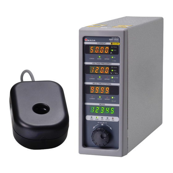
The MM-140A has the following features. • Compact body The outline is 187 x 70 x 250 (mm) and the weight is 2.3 kg. The MM-140A can be installed anywhere and can be carried easily. • Supports a long-time welding current A long-time pulsed TIG welding can be measured with 9999 ms of the maximum measurement time. -
Page 9: Packaging
MM-140A 3. Packaging (1) Accessories The model numbers of accessories are subject to change without notice. Depending on the part to be changed, the mounting screw shape may change and a necessary tool may be different. For the latest parts information, contact a nearest sales office. - Page 10 I/O connection cable with connector SK-1210082 (10 m) SK-1210083 (20 m) *1: Exclusively for the MM-140A. Do not use for other devices. *2: The identification diagram of the I/O connection cable with connector’s core is shown below. Example) Pin 49, White (■■■Black) Orange (■Black)
-
Page 11: Recommended Parts
MM-140A (3) Recommended Parts Item Model No. PF2M7 series, analog output 4 mA to 20 mA product Shield gas flow sensor (example of SMC, PF2M710-C6-D-M) Ferrite core E04SRM381913 (manufactured by SEIWA) *1: Ar is recommended for the shield gas flow sensor. For detail specifications, contact the manufacturer. -
Page 12: Name And Functions Of Each Section
MM-140A 4. Name and Functions of Each Section (1) Front ⑩No-current LED ⑪Peak welding current measurement LED ⑫Effective value of welding current measurement LED ①Welding current display ⑬50A-range LED ②Welding current upper/ ⑭300A-range LED lower limit judgment LEDs ⑮Peak torch ③Torch voltage/modulation... - Page 13 MM-140A Welding current display Displays the selected measurement results of the current (peak or effective value) and the set value for the current upper/lower limit judgment. Welding current upper/lower limit judgment LEDs Indicate the result of the current upper/lower limit judgment. There are three LEDs, UPPER, GOOD and LOWER.
- Page 14 MM-140A When the measured weld time is the upper limit or lower GOOD (green) and the lower limit or higher. lights up (When the measured external input (shield gas flow rate) is the upper limit or lower and the lower limit or higher.) When the measured weld time is lower than lower limit.
-
Page 15: Rear
MM-140A (2) Rear ①LAN cable connector ②Service connector ③I/O connector ⑥Torch voltage connector ⑦Current sensor/external input (shield gas flow rate) connector ⑧Power supply switch ④Power cable connector ⑨Fuse holder ⑤Grounding terminal 4. Name and Functions of Each Section... - Page 16 Connects to the power cable (option) when the single-phase AC power supply (100–240 V) is used. Grounding terminal Be sure to ground the MM-140A before use. Torch voltage connector Connects to the torch voltage detection cable (option). Current sensor/external input (shield gas flow rate) connector ...
-
Page 17: Interface
MM-140A 5. Interface (1) Connection Diagram of the External I/O Signals Description of each pin on the I/O connector. Input signal is explained as contact input. INT.24V EXT.COM SCH1 SCH2 SCH4 SCH8 SCH16 EXTERNAL_IN COUNT RST NO CURR NG RESET... - Page 18 MM-140A INT.24V NG+24V(-) NG+24V(+) NG-L NG-H NG COM RANGE OVER GOOD NO CURR READY COUNT UP 5. Interface...
-
Page 19: Description Of The External I/O Signals
MM-140A (2) Description of the External I/O Signals Pin No. Name Function Pins 1, 26, 27, and 28 are pins for the INT.24V. Pin 2 is the EXT.COM. Connect pins as follows: INT.24V When using contacts or NPN transistors (sink type) on a PLC as input signals to the I/O connector, connect either of INT.24V terminals and... - Page 20 MM-140A Pin No. Pin No. SCH No. SCH No. ● ● ● ● ● ● ● ● ● ● ● ● ● ● ● ● ● ● ● ● ● ● ● ● ● ● ● ● ● ● ●...
- Page 21 MM-140A Pin No. Name Function The trigger input terminal of external I/O for start measurement of the external input (shield gas flow rate). EXTERNAL_ The shield gas flow rate is measured by using the opening/closing signal of the solenoid valve as a trigger.
- Page 22 2.5 ℓ.) Analog output signal terminal for the trigger state. TRG SIG Approx. 3.3 V is output while the MM-140A is operating for measurement. Analog output signal terminal for the voltage between torches.
- Page 23 MM-140A Pin No. Name Function The circuit between Pins 37 and 40 is output pin for the [NG] or [NG-L] NG‐H signal. Function is switched by the system setting. For details, see [7. (5) e. System Setting (1) Upper/lower limit NG‐L...
- Page 24 MM-140A Pin No. Name Function The circuit between Pins 39 and 40 is output pin for the [NG] or [NG-H] NG‐H signal. Function is switched by the system setting. For details, see [7. (5) e. System Setting (1) Upper/lower limit NG‐L...
- Page 25 MM-140A Pin No. Name Function NG COM Common terminal for NG-L and NG-H output signals. Output pins for the [RANGE OVER] signal. RANGE OVER Close for the fixed time when the measured value is out of the measurable range of each range.
-
Page 26: Connection Of Input Signals
MM-140A (3) Connection of Input Signals a. Connection with Device Having a Contact Input (when Using Internal Power Supply) Connect pins 1 and 2. Internal External 内部 外部 INT.24V 1) INT.24V EXT.24V EXT.COM 2) EXT.COM EXT.COM SCH1 3) SCH1 SCH2 4) SCH2 ... -
Page 27: Connection With Device Featuring Npn Open Collector Output (When Using Internal Power Supply)
MM-140A b. Connection with Device Featuring NPN Open Collector Output (when Using Internal Power Supply) Connect pins 1 and 2. Internal External 内部 外部 INT.24V 1) INT.24V EXT.24V EXT.COM 2) EXT.COM EXT.COM 3) SCH1 SCH1 SCH2 4) SCH2 ・ ・ ... -
Page 28: Connection With Device Featuring Pnp Current Output (When Using External Power Supply)
MM-140A c. Connection with Device Featuring PNP Current Output (when Using External Power Supply) Connect the negative side of an external 24 V DC power supply to pin 2. Internal External 内部 外部 EXT.24V No connection 1) 未接続 ⊕ EXT.COM EXT.COM 2) EXT.COM... -
Page 29: Connection With Device Featuring Npn Open Collector Output (When Using External Power Supply)
MM-140A d. Connection with Device Featuring NPN Open Collector Output (when Using External Power Supply) Connect the positive side of an external 24 V DC power supply to pin 2. Internal External 内部 外部 EXT.24V No connection 1) 未接続 ⊕ EXT.COM EXT.COM... -
Page 30: Installation And Connections
Current sensor (RS-C300-3000) b. Connecting the Torch Voltage Detection Cable (Option) Exclusively for the MM-140A. Since “White line is +” and “black line is -”, the voltage cannot be measured when connected in an opposite way. Take care of it. -
Page 31: Connecting The Shield Gas Flow Sensor Cable (Option)
Torch voltage detection cable Current sensor The torch voltage can be measured only by the touch-start model. Connect the shield of the torch voltage detection cable to the same FG as the MM-140A (checker main unit). 6. Installation and Connections... - Page 32 Shield gas flow sensor cable The torch voltage can be measured only by the touch-start model. Connect the shield of the torch voltage detection cable to the same FG as the MM-140A (checker main unit). 6. Installation and Connections...
- Page 33 MM-140A Example connection between the shield gas flow sensor cable (SK-1202981) and the shield gas flow sensor (PFM7) 3000mm PF2M7 (input connector) Pin No. Color Contents DC(+) OUT2/ analog output OUT1 DC(-) Analog (4 mA – 20 mA) 6. Installation and Connections...
-
Page 34: Connecting The Communication Connector
LAN cable Example connection 2) To connect the MM-140A and PC one-on-one, prepare a LAN cable (option). * Install the attached ferrite core (NFT-12) as shown below. If the communication is interrupted under a high noise environment, install the recommended E04SRM381913 (manufactured by SEIWA) by passing the cable through it four times. -
Page 35: Basic Operation
MM-140A 7. Basic Operation (1) Startup Connect the current sensor (option). Set the power supply switch on the rear panel to the ON position (– side). * Be sure to turn on the power after connecting a current sensor, otherwise it affects the measurement function. -
Page 36: Basic Usage Of The Mm-140A
SCH (schedule) Mode The MM-140A can set 31 schedules of the upper/lower limit of the welding current, torch voltage, modulation frequency, weld time, and external input (shield gas flow rate). In this mode, the present schedule number is displayed, and the schedule number to measure is set. -
Page 37: Prg (Program) Mode
* The preset counter value currently set is displayed on the mode display. SCH setting mode This mode is for setting schedules. The MM-140A can set 31 types of upper/lower judgment schedules of welding current, torch voltage, modulation frequency, weld time, and external input (shield gas flow rate). - Page 38 MM-140A To input or change each setting, the MM-140A is required to be set in the program mode. To prevent schedules from being changed by mistake, there are two modes, the supervisor mode and the operator mode. The differences are as follows:...
-
Page 39: Simply Selecting The External Input (Shield Gas Flow Rate) Display
When the mode is returned from the program mode to the measurement mode or the MM-140A starts measurement, the display returns to the SCH setting. The display at the simple selection returns to the SCH setting after welding. For details, see [7. - Page 40 MM-140A When the mode is returned from the program mode to the measurement mode or the MM-140A starts measurement, the display returns to the SCH setting. The display at the simple selection returns to the SCH setting after welding. For details, see [7.
-
Page 41: Preparation For Measurement
MM-140A (3) Preparation for Measurement To measure the welding current, the following settings of “a” to “e” are necessary. (To measure the peak value, the setting of “f” is unnecessary.) a. Selecting the schedule number to set b. Selecting the peak and effective values of welding current c. -
Page 42: Selecting Peak Or Effective Value Of Welding Current
Press the operation button for one second to cancel the program mode. Selecting Peak or Effective Value of Welding Current The welding current measured in the MM-140A can be displayed as the effective value or the peak value for each welding schedule. -
Page 43: Selecting Torch Voltage Or Modulation Frequency
Various Levels (6) modulation frequency measurement threshold current value]. Selecting Peak or Effective Value of Torch Voltage The torch voltage measured in the MM-140A can be displayed as the effective value or the peak value for each welding schedule. Effective value from measurement start time The value of the (FIRST) to measurement end (LAST). -
Page 44: Selecting Weld Time Or External Input (Shield Gas Flow Rate)
Press the operation button for one second while the PRG is on to set the MM-140A in the program mode. (Input a password in the operator mode.) Turn the operation button to turn on the weld time LED or the external input (shield gas flow rate) LED. - Page 45 MM-140A Press the operation button for one second while the PRG is on to set the MM-140A in the program mode. (Input a password in the operator mode.) F R 5 T Turn the operation button to display on the torch voltage/modulation frequency display.
-
Page 46: Upper/Lower Limit Judgment Function
MM-140A (4) Upper/Lower Limit Judgment Function The MM-140A is equipped with the upper/lower limit judgment function for welding current, torch voltage, modulation frequency, weld time, and external input (shield gas flow rate). The upper/lower limit judgment can be set for each schedule number. -
Page 47: Setting The Upper And Lower Limits Of The Torch Voltage
Press the operation button for one second while the PRG is on to set the MM-140A in the program mode. (Input a password in the operator mode.) Turn the operation button to turn on the LOWER of the welding current upper/lower limit judgment LEDs. -
Page 48: Setting The Upper And Lower Limits Of The Weld Time
Turn the operation button to turn on the PRG of the mode selection LEDs. Press the operation button for one second while the PRG is on to set the MM-140A in the program mode. (Input a password in the operator mode.) When the torch voltage/modulation frequency display is set to the modulation frequency, turn the operation button to change the setting to the torch voltage. -
Page 49: Setting The Upper And Lower Limits Of The External Input (Shield Gas Flow Rate)
Press the operation button for one second while the PRG is on to set the MM-140A in the program mode. (Input a password in the operator mode.) When the weld time/external input (shield gas flow rate) display is set to the external input (shield gas flow rate), turn the operation button to change the setting to the weld time. -
Page 50: Setting The Upper And Lower Limits Of The Modulation Frequency
Press the operation button for one second while the PRG is on to set the MM-140A in the program mode. (Input a password in the operator mode.) When the weld time/external input (shield gas flow rate) display is set to the weld time, turn the operation button to change the setting to the external input (shield gas flow rate). - Page 51 Press the operation button for one second while the PRG is on to set the MM-140A in the program mode. (Input a password in the operator mode.) 3) When the torch voltage/modulation frequency display is set to the torch voltage, turn the operation button to change the setting to the modulation frequency.
-
Page 52: Settings In The Program Mode
MM-140A (5) Settings in the Program Mode Setting the Preset Counter (COUNT) The MM-140A has the preset counter function. The preset counter is common to 31 schedules. The counter proceeds by 1 when the measurement results of all selected measurement items are within the upper/lower limit. -
Page 53: Changing The Various Levels
Press the operation button for one second while the PRG is on to set the MM-140A in the program mode. (Input a password in the operator mode.) Turn the operation button left to turn on the STATUS of the mode selection LEDs. - Page 54 MM-140A c u t r 9 (1) Current trigger level ( Due to influence of noise or status of welding current, a malfunction such as “a measurement is not performed even when the current flows” or “a measurement starts even though a current does not flow”...
- Page 55 MM-140A E x t r 9 (4) External input (shield gas flow rate) measurement start level ( 1) When the operation button is pressed, the currently set external input (shield gas flow rate) measurement start level is displayed with blinking.
- Page 56 MM-140A ● EXTERNAL_IN (external I/O input) The measurement section is the input section of the EXTERNAL_IN signal of section A. When no current flows while the EXTERNAL_IN signal is input, the measurement becomes invalid and cannot be performed. Section A (EXTERNAL_IN signal input section) Section A (EXTERNAL_IN signal input section)
- Page 57 MM-140A Measurement section Measurement start Measurement end time (FIRST) time (LAST) Main welding Initial welding Main welding Initial welding As shown in the figures (A) and (B), when the initial weld time is not constant due to a stroke of the welding head, the main welding and the measurement section may be deviated and the measurement result may change significantly.
- Page 58 MM-140A F r 9 (6) Modulation frequency measurement threshold current value ( 1) When the operation button is pressed, the currently set modulation frequency measurement threshold current value is displayed with blinking. When 50-A range is selected, the initial value is 00.00.
- Page 59 MM-140A ends. *2: It may be difficult to measure the modulation frequency in the following operating environment. ・The modulation frequency is high. ・The difference between welding current and base current is small. ・The duty ratio of modulation is large. ・A ripple of a welding current is large.
- Page 60 MM-140A MAWA power supply MM-140A modulation threshold setting Modulation frequency Duty 90 % Duty 50 % Duty 10 % setting 10Hz 20Hz 30Hz 40Hz 50Hz 60Hz 70Hz 80Hz 90Hz 100Hz 200Hz 300Hz 400Hz 500Hz 600Hz 700Hz 800Hz 900Hz 1000Hz 1100Hz...
-
Page 61: Communication Setting
Press the operation button for one second while the PRG is on to set the MM-140A in the program mode. (Input a password in the operator mode.) Turn the operation button left to turn on the STATUS of the mode selection LEDs. - Page 62 MM-140A IP address: Specifies the computer by address on network. Communication can be done by inputting the set value to the PC. Subnet mask: 5 u b Value for dividing IP address into network address and host address. Communication can be done by inputting the set value to the PC.
- Page 63 MM-140A 13) When the operation button is pressed, the setting screen is displayed and the right place blinks. When the operation button is turned, the number changes. When the operation button is pressed, the place changes. 1 9 2. 1 9 2.
-
Page 64: System Setting
MM-140A System Setting The contents of the system setting and 7-segment LED display are as follows: System setting (1) Upper/lower limit judgment output operation (2) Error output (3) Current range selection (4) External input (shield gas flow rate) measurement end extension time... - Page 65 MM-140A Item Contents (2) Error output HL no: Pins 37, 39 and 40 on the I/O connector are opened in normal status. When the measured value is outside the setting of the upper/lower limit judgment or a trouble occurs, the circuits are closed.
- Page 66 Press the operation button for one second while the PRG is on to set the MM-140A in the program mode. (Input a password in the operator mode.) Turn the operation button left to turn on the STATUS of the mode selection LEDs.
- Page 67 MM-140A <Setting operation procedure> The setting items are switched as shown below. Change the setting by the operation button. The set value is displayed at the leading screen. ・Turn the button ・Turn the button ・ Press the button. right and left.
-
Page 68: External Input (Shield Gas Flow Rate) Measurement End Extension Time
Press the operation button for one second while the PRG is on to set the MM-140A in the program mode. (Input a password in the operator mode.) Turn the operation button left to turn on the STATUS of the mode selection LEDs. - Page 69 MM-140A 5 y 5 When the operation button is pressed, is displayed on the mode display. Press the operation button. P A 5 5 Turn the operation button to display on the mode display. When the operation button is pressed, the current password is displayed on the mode display.
-
Page 70: Checking Settings And Initializing
MM-140A returns to the measurement operation. The settings other than this can be checked in the program mode. When the operation button is turned, the display of the MM-140A is switched in the order of When the operation button is pressed twice (within 0.5 ms), only the schedule number is displayed. - Page 71 MM-140A <When the modulation frequency display is set> The LOWER of the torch voltage/modulation frequency upper/lower limit judgment LED lights up. The lower limit of the modulation frequency for the schedule number displayed presently is also displayed on the weld time/external input (shield gas flow rate) display.
-
Page 72: Initializing The Schedule Setting
MM-140A number displayed presently is also displayed on the weld time/external input (shield gas flow rate) display. (The initial setting is 99.9.) 13) The “First” is displayed on the torch voltage/modulation frequency display. The measurement start time is displayed on the weld time/external input (shield gas flow rate) display. -
Page 73: Data Communication
MM-140A 8. Data Communication Monitoring data can be loaded from the MM-140A into the external PC. Also, schedule settings can be written from the external PC into the MM-140A. (1) Data Transfer Item Description System Ethernet IEEE 802.3-compliant (10BASE-T/100BASE-TX protocol TCP/IP) - Page 74 [IP address setting] Set the IP address of the personal computer. The IP address of the MM-140A has been set to [192.168.1.10] at the factory. Use [192.168.1.11] or later for the IP address of the personal computer. However, do not set the IP address to the same as the default gateway.
- Page 75 MM-140A Click the [Properties]. Select the [Internet Protocol Version 4(TCP/IPv4)] and click the [Properties]. 8. Data Communication...
- Page 76 Now the IP address setting is completed. Set 1024 to 5000 for the port number. When you change the setting of the MM-140A, turn off the power supply, or disconnect the LAN cable, connect the MM-140A again. 8. Data Communication...
-
Page 77: Communication Protocol (Single-Directional Communication)
Communication) Refer to [7. (5) d. Communication Setting] to set the communication method to Ethernet single-directional communication. Data is output one-sidedly from the MM-140A after the welding current has measured and a fault has occurred. a. Monitor Data Commands transmitted from the MM-140A to the host computer is as follows:... - Page 78 37 Feed code [LF] (0x0a) Communication example of single-directional communication (monitor data) Monitor data of Device number 01 and Schedule number 1 (current range: 300 A) is transmitted to the MM-140A. “MM-140A → Host computer” !01001S01:00138,G,252.3A,G,249.8A,G,020.2V,G,016.4V,G,00.0,G,0000Hz,G,0153ms[CR] [LF] 8. Data Communication...
-
Page 79: Error Data
Feed code [LF] (0x0a) Communication example of single-directional communication (error data) The following data is transmitted from the MM-140A set to Device number 01 and Schedule number 1 when the preset counter is counted up “MM-140A → Host computer” !01001E:99999,13[CR][LF] ... -
Page 80: Communication Protocol (Bi-Directional Communication)
Do not send the next command until the data is sent back or the timeout time passes when sending command. When using write command, a newly set data is returned from the MM-140A for check. Compare the schedule of write command with that of the data sent back to check that it has been correctly changed. - Page 81 MM-140A Item Display Range Length U: Upper limit error G: Normal Peak current judgment L: Lower limit error O: Range over error 10 Delimiter nn.nnA 00.00 to 60.00A (50A range) 11 Peak current value nnn.nA 000.0 to 350.0A (300A range)
- Page 82 37 Feed code [LF] (0x0a) Communication example of bi-directional communication (reading the monitor data) Reading the monitor data of Device number 02 and Schedule number 3 (current range: 300 “Host computer → MM-140A” #02R003S01*[CR][LF] “MM-140A → Host computer” !02003S01:00138,G,252.3A,G,249.8A,G,020.2V,G,016.4V,G,00.0,G,0000Hz,G,0153ms[CR] [LF] 8.
-
Page 83: Reading And Writing The Level Setting Data And System Setting Data
MM-140A b. Reading and Writing the Level Setting Data and System Setting Data <Reading request data> Commands transmitted from the host computer to the MM-140A is as follows: Item Display Range Length Start code Device number 01 to 31 Read code... - Page 84 [CR] (0x0d) Feed code [LF] (0x0a) Communication example) !01001S11:00010,1,50%,05%,05%,00.0,00%,000.0A,0,0,00000ms,0.4,01ms,1,1 (factory setting) <Writing request data> Commands transmitted from the host computer to the MM-140A is as follows: Item Display Range Length Start code Device number 01 to 31 Write code Schedule number...
- Page 85 Writing the level setting data and system setting data of Device number 03 (current range: 300 A) “Host computer → MM-140A” #03W000S11:00000,1,50%,05%,05%,00.0,00%,000.0A,0,0,00000ms,0.4,01ms,1,1[CR][LF] “MM-140A → Host computer” (sent for check when the written data is within the setting range.) !03000S11:00000,1,50%,05%,05%,00.0,00%,000.0A,0,0,00000ms,0.4,01ms,1,1[CR][LF] 8. Data Communication...
-
Page 86: Reading And Writing The Schedule Setting Data
MM-140A c. Reading and Writing the Schedule Setting Data <Reading request data> Commands transmitted from the host computer to the MM-140A is as follows: Item Display Range Length Start code Device number 01 to 31 Read code Schedule number 001 to 031... - Page 87 0000 to 3500Hz Return code [CR] (0x0d) Feed code [LF] (0x0a) <Writing request data> Commands transmitted from the host computer to the MM-140A is as follows: Item Display Range Length Start code Device number 01 to 31 Read code...
- Page 88 Writing the schedule setting data of Device number 02 and Schedule number 1 (current range: 300 A) “Host computer → MM-140A” #02W001S10:5000ms,0000ms,0000ms,0000ms,01,350.0A,000.0A,350.0A,000.0A,01,120.0 V,000.0V,120.0V,000.0V,10.0,00.0,3000Hz,0000Hz[CR][LF] “MM-140A → Host computer” (sent for check when the written data is within the setting range.) !02001S10:5000ms,0000ms,0000ms,0000ms,01,350.0A,000.0A,350.0A,000.0A,01,120.0V, 000.0V,120.0V,000.0V,10.0,00.0,3000Hz,0000Hz[CR][LF] 8. Data Communication...
-
Page 89: Reading The Communication Setting Data
MM-140A d. Reading the Communication Setting Data <Reading request data> Commands transmitted from the host computer to the MM-140A is as follows: Item Display Range Length Start code Device number 01 to 31 Read code Schedule number 001 to 031... - Page 90 Feed code [LF] (0x0a) Communication example bi-directional communication (reading the communication setting data) Reading the communication setting data of Device number 01 “Host computer → MM-140A” #01R000S20*[CR][LF] “MM-140A → Host computer” !01000S20:2,01,192␣168␣␣␣1␣␣10,255␣255␣255␣␣␣0,192␣168␣␣␣1␣ 100,1024[CR][LF] (Note) “␣” indicates a space. 8. Data Communication...
-
Page 91: Fault Code List
MM-140A 9. Fault Code List The MM-140A lets you know the occurrence of troubles by lighting up LEDs or displaying fault codes. Fault code Cause Measures (Display name) • Trouble of the flash memory Depress the operation button. • A part of schedule setting... - Page 92 In that case, even when the MAWA welding power supply displays GOOD, the MM-140A becomes NG in the upper/lower limit judgment. Adjust it by the current trigger threshold and forced measurement time.
-
Page 93: Specifications
MM-140A 10. Specifications (1) Measurement Specification Target Specification [Each schedule] Measurement range ・01.00–50.00 A ・015.0–300.0 A [Common to all schedules] ・Peak value Peak value within weld section (all Current Measurement item sections) ・Effective value Effective value between start and end Measurement ±2% (full scale) (excluding sensor error) - Page 94 MM-140A Upper/lower limit judgment of current (31 schedules) Upper/lower limit judgment of voltage (31 schedules) Upper/lower limit judgment of weld time (31 Judgment function schedules) Upper/lower limit judgment of external input (shield gas flow rate) (31 schedules) Upper/lower limit judgment of modulation...
-
Page 95: Specification Of The Mm-140A
MM-140A (2) Specification of the MM-140A Item Specification Welding current, torch voltage (touch-start model only), Display contents weld time, external input (shield gas flow rate), modulation frequency Signal Refer to [5. Interface]. Contacts, NPN transistors (sink type), and PNP transistors (source type) can be connected. - Page 96 MM-140A *1: Use this product in the environment without conductive dust. If conductive dust enters in the product, this may result in a failure, electric shock, or fire. When using this product in this environment, make contact with us. 10. Specifications...
-
Page 97: Calibration
For calibration, please send your current sensor together with the MM-140A. Depending on the operating environment, the extent of deterioration varies from one MM-140A to another. Therefore, the MM-140A must be calibrated together with the current sensor as a set. For more information about calibration, contact us. -
Page 98: Outline Drawing
MM-140A 12. Outline Drawing (1) Body (Dimensions in mm) 12. Outline Drawing 12-1... -
Page 99: Drawings For Mounting Bracket
MM-140A (2) Drawings for Mounting Bracket (Dimensions in mm) a. Front and Rear Mounting (30) φ4.5 b. Right and Left Mounting φ4.5 12. Outline Drawing 12-2... -
Page 100: Current Sensor (Common To Rs-C300-3000/Rs-C050-3000)
MM-140A (3) Current Sensor (Common to RS-C300-3000/RS-C050-3000) (Dimensions in mm) Cable length: approx. 3000mm 12. Outline Drawing 12-3... -
Page 101: Index
MM-140A Index Accessories ............3-1 Password Setting ..........7-34 Calibration ............11-1 Rear................4-4 Communication Setting ........7-27 Recommended Parts ..........3-3 Data Communication ..........8-1 Specifications ............10-1 Disposal ..............1-4 Startup ..............7-1 System Setting .............7-30 Fault Code List ............9-1 Front ..............4-1 Upper/Lower Limit Judgment Function ....7-12...
Need help?
Do you have a question about the MM-140A and is the answer not in the manual?
Questions and answers