Table of Contents
Advertisement
Quick Links
Advertisement
Table of Contents

Subscribe to Our Youtube Channel
Related Manuals for Amada WELD CHECKER MM-400B


Summary of Contents for Amada WELD CHECKER MM-400B
- Page 1 Original instructions WELD CHECKER ® MM-400B OPERATION MANUAL AA04OM1210785-01...
-
Page 2: Table Of Contents
MM-400B Thank you for your purchase of our Weld Checker MM-400B. Please read this manual carefully to ensure correct use. Keep the manual handy after reading for future reference. Contents Special Precautions ...................... 1-1 (1) Safety Precautions ..................... 1-1 (2) Precautions for Handling .................... 1-4 (3) Model-Specific Function ..................... - Page 3 MM-400B b. MEASUREMENT Screen ........................8-6 c. VIEW Screen ............................8-9 d. WAVEFORM Screen ......................... 8-14 e. COMPARATOR Screen ........................8-18 f. ENVELOPE Screen ........................... 8-21 g. HISTORY Screen..........................8-37 h. PRINT Screen ............................ 8-41 i. USB Screen ............................8-45 j.
- Page 4 MM-400B (4) Communication Protocol (Bi-Directional Communication) ........12-22 (5) Code Table of Communication and USB Data ............12-60 13. Error List and Maintenance ..................13-1 (1) Troubleshooting ....................... 13-1 (2) Replacing the Battery ....................13-7 a. Necessary items ..........................13-7 b.
-
Page 5: Special Precautions
MM-400B 1. Special Precautions (1) Safety Precautions Before using the weld checker, please read through the Safety Precautions carefully to ensure proper use. The precautions listed here are designed to ensure safe use and proactively prevent risks and damage to the user and other people. All precautions are critical for safety. Please read them all. - Page 6 MM-400B DANGER NEVER ATTEMPT to disassemble, repair or modify the instrument. Do not touch any parts inside the instrument. Failure to observe this may result in an electric shock or fire. For battery replacement, inspection or repair, please contact your dealer or us. NEVER burn, destroy, cut, crush or chemically decompose the instrument.
- Page 7 MM-400B CAUTION ALWAYS wear protective goggles. Directly looking at surface flash and expulsion during welding can temporary impair vision. Welding spatter can cause permanent eye damage, including blindness. DO NOT splash water. Electrical parts may cause an electric shock or short circuit if they become wet. Keep the area clear of flammable objects.
-
Page 8: Precautions For Handling
MM-400B (2) Precautions for Handling Avoid the following locations when installing the instrument: ■ • Humid (above 90%) locations • Extremely hot (above 45°C) or cold (below 0°C) locations • Near a high noise source • Location where chemical substances, etc. are handled •... -
Page 9: On Disposal
MM-400B (5) On Disposal This product incorporates parts containing gallium arsenide (GaAs). At the time of disposal, separate it from general industrial waste or domestic waste and carry out the disposal in accordance with applicable laws and regulations. (6) Warning Labels A warning label is pasted on the instrument for safe use. -
Page 10: Features
MM-400B 2. Features The Weld Checker MM-400B is a measuring instrument designed for stationary resistance welding machines. The instrument can measure the current, voltage, current flow time, force , displacement external voltage input (max. ±10 V) and external current input (4 to 20 mA) and display their waveforms. - Page 11 MM-400B • Envelope function The envelope function (making the OK/NG judgment by comparing a waveform within an allowable range and a monitored waveform) enables management with waveforms in addition to conventional measured values. • Measurement with seam current Measures current/voltage in AC welding or voltage in DC welding with a max. 5-minute moving measurement.
-
Page 12: Packaging
MM-400B 3. Packaging Check the contents of the package. In the case of damaged or missing items, please contact (1) Accessories The model numbers of accessories are subject to change without notice. Depending on the part to be changed, the mounting screw shape may change and a necessary tool may be different. -
Page 13: Options
MM-400B (2) Options a. For MM-400B-00-00/-00-01/-00-10/-00-11 Item Model KP-35 KS-16A SVT#18×3 B-TYPE (3-pin plug, for 100–120 V AC) (cable length 3 m) KP244 VCTF3*115 KS16D 3m Gray Power cable (Japan, for 200 V AC) (cable length of 3 m) CEE3P-W-1.8 (round plug, for 200–240 V AC) (cable length of 1.8 m) 3-pin/2-pin conversion KPR-24(SB)-B... - Page 14 MM-400B c. Exclusively for MM-400B-00-01/-00-11 Item Model DS 500A/100MV (range between 25 A and 500 A) Shunt resistor DS 1000A/100MV (range between 50 A and 1000 A) Current/force sensor MA-770A-01 (4903 N (500 kgf) max.) (put between electrodes for MA-771A-01 (9806 N (1,000 kgf) max.) measurement) Z-04715-002 (with groove) Replacement plate...
- Page 15 MM-400B Item Model LG200-110 (10 mm) (cable length of 2.5 m) Displacement sensor LG100-125 (25 mm) (cable length of 2 m) (Mitutoyo) LG100-150 (30 mm) (cable length of 2 m) Displacement sensor SK-1211379 (cable length of 0.15 m) extension cable Displacement sensor No.21HZA197 (cable length of 5 m) extension cable...
-
Page 16: Name And Functions Of Each Section
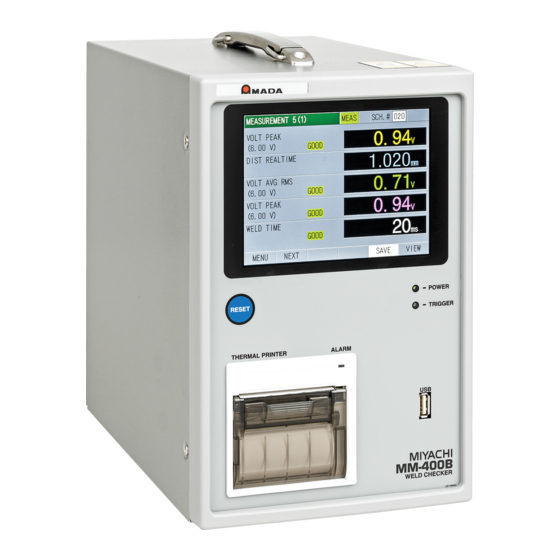
MM-400B 4. Name and Functions of Each Section (1) Front [RESET] button: Resets an error that has occurred. [POWER] lamp: Lit when the power is ON. [TRIGGER] lamp: Lit during the measurement operation. Printer: ... -
Page 17: Rear
MM-400B (2) Rear ⑫ ⑪ External I/O connector (1): A connector to input signals from peripheral devices. External I/O connector (2): A connector to output signals to peripheral devices. RS-232C/RS-485 connector: ... - Page 18 MM-400B Main power switch: Switch for the main power. Set this to the ON position (– side) to start the MM-400B. Power cable connector: ○ Plug the power cable into this connector. LAN cable connector: ○ Plug the LAN cable for Ethernet into this connector. The orange LED is lit when it can be connected and is blinked when the data is being sent or received.
-
Page 19: Operation Flow
MM-400B 5. Operation Flow The operation flow is shown below. Install the MM-400B (Refer to (1) in Chapter 6) Device connection Connect with other Connect measurement devices to the MM-400B devices Displacement Current Voltage Force Sequencer measurement measurement measurement measurement Voltage Displacement Toroidal coil... -
Page 20: Installation And Connections
MM-400B 6. Installation and Connections (1) Installing the MM-400B Place the MM-400B on a stable surface. Avoid locations where vibration is generated or the MM-400B rotates or moves. Connect the power cable to the power cable connector [INPUT POWER] on the rear panel. -
Page 21: Preparations For Measurement - Connection Between The Mm-400B And Measurement Devices
MM-400B (2) Preparations for Measurement – Connection between the MM-400B and Measurement Devices a. Connecting the Toroidal Coil and the Voltage Detection Cable To measure the current or voltage, connect the toroidal coil and the voltage detection cable to the rear panel of the MM-400B. Toroidal coil connector Toroidal coil (e.g., MB-400P) - Page 22 MM-400B • Keep the toroidal coil’s hooking bracket as far away from the welding machine’s arm (secondary conductor) as possible. • Do not deform the circular form of the toroidal coil when fitting it. Do not deform the circular form of the toroidal coil. Keep the hooking bracket at the furthest point from the arm.
- Page 23 MM-400B Plug the voltage detection cable connector into the voltage detection cable connector [V-SENS] on the rear panel of the MM-400B. Connect the voltage measurement cables to the electrodes (positive/negative). (Note) To properly perform a voltage detection The voltage detection cable picks up voltage induced by the welding current. To measure the voltage between the tips, connect the cable as shown below.
-
Page 24: Connecting The Displacement Sensor (Force/Displacement-Equipped Specification)
MM-400B b. Connecting the Displacement Sensor (Force/displacement-equipped specification) As a force/displacement-equipped specification function, the MM-400B can measure displacement. To measure displacement, connect a displacement sensor. We recommend the following displacement sensors: Item Model Connector Displacement sensor LGK-110 (10 mm) DISPLACEMENT1 (Mitutoyo) LG200-110 (10 mm) Displacement sensor... - Page 25 MM-400B Follow the steps described below to connect the displacement sensor. Plug the displacement sensor connector into the displacement sensor connector [DISPLACEMENT1] or [DISPLACEMENT2] on the rear panel of the MM-400B. (Caution) Connect the displacement sensor either to [DISPLACEMENT1] or [DISPLACEMENT2].
- Page 26 MM-400B ATTENTION As the figure (A) below, be sure to keep the displacement sensor perpendicular to the Displacement Detecting Plate. If Displacement Sensor is slantingly installed like (B) or (C), the life of the sensor becomes shorter. [Normal] [Abnormal] [Abnormal] θ...
-
Page 27: Connecting The Force Sensor (Force/Displacement-Equipped Specification)
MM-400B c. Connecting the Force Sensor (Force/displacement-equipped specification) The MM-400B can measure, as a force/displacement-equipped specification function, force when connected with force sensor MA-520B/521B/522B, pressure follow-up mechanism element P unit, or current/force sensor MA-770A/771A. Current/force sensor MA-770A/771A incorporates a current sensor (toroidal coil), making it possible to measure force and current at the same time simply by applying a force and passing a current. - Page 28 MM-400B Attach the force sensor to the welding machine’s electrodes. When attaching the sensor, be careful with the following: Align the centers. • Be sure that the center of the sensor’s Apply force detection area is aligned with the centers of perpendicularly.
- Page 29 MM-400B Attach the current/force sensor to the welding machine’s electrodes. When attaching the sensor, be careful with the following: • Be sure that the center of the sensor’s detection area Welding head is aligned with the centers of Electrode the welding machine’s Clamp the electrodes.
-
Page 30: When Using An External ±10 V Voltage Input (Force/Displacement-Equipped Specification)
MM-400B d. When Using an External ±10 V Voltage Input (Force/displacement-equipped specification) The MM-400B allows for displaying the measured voltage signal using a commercial sensor and amplifier connected to the external ±10 V voltage input. Follow the steps described below to connect the external ±10 V voltage. External ±10 V Voltage Input Connection Diagram Sensor amplifier 16-pin female... -
Page 31: When Using An External 4 To 20 Ma Current Input (Force/Displacement- Equipped Specification)
MM-400B e. When Using an External 4 to 20 mA Current Input (Force/displacement- equipped specification) The MM-400B allows for measurement connecting a commercial 4 to 20 mA output sensor connected to the external current input. Input it in a range of 4 to 20 mA. -
Page 32: When Using A Shunt Resistor (Force/Displacement- Equipped Specification)
MM-400B f. When Using a Shunt Resistor (Force/displacement- equipped specification) The MM-400B allows for current measurement connecting a shunt resistor connected to the shunt resistor input. A shunt resistor is a resistor for detecting current of a circuit. It is connected in series to the welding current circuit. - Page 33 MM-400B (Reference) Current measurement by a shunt resistor The shunt resistor detects a current in circuit. As shown below, connect it to welding current circuit in series. Be sure to use the shunt with floating off the ground. Since the resistance value changes by heat generation, be careful of use with large current or high duty cycle.
-
Page 34: Basic Operation
MM-400B 7. Basic Operation (1) Startup Set the main power switch on the rear panel to the ON position (– side). The MEASUREMENT 5(1) or MEASUREMENT 10 screen appears on the display after a while. (The MEASUREMENT 5(1) screen appears first used after shipment.) To display a waveform or change or check the setting, touch MEAS to change it to PROG. -
Page 35: Changing The Display Language
MM-400B (2) Changing the Display Language Touch the MENU key on the lower-left portion of the screen. The MENU screen appears. Select SYSTEM SETUP. The SYSTEM SETUP (1) screen appears. The display language can be changed by the LANGUAGE setting. Select a language to display. - Page 36 MM-400B • Selecting an item in the VIEW screen In this screen example, the cursor is positioned at the DISPLAY selection field. The settable item is switched by “+” and “-.” Since the setting items do not loop, only “+” or “-” appears when the setting limit is reached. After selection, touch ENT to determine.
- Page 37 MM-400B • Selecting a mode In this screen example, the cursor is positioned at the TRIGGER selection field. The settable item is switched by “+” and “-.” Since the setting items do not loop, only “+” or “-” appears when the setting limit is reached. After selection, touch ENT to determine.
- Page 38 MM-400B (iii) Alphabetical characters (J to R) (iv) Alphabetical characters (S to Z) Move to (iv) by > and (ii) by <. Move to (iii) by <. Enable the function keys. Touching the function keys at the lower portion of the screen loads screens or enables various functions.
- Page 39 MM-400B • Scrolling the HISTORY screen. Touching the CHANGE key on the at the lower portion of the HISTORY screen displays ← → to switch ten measurement items selected in the VIEW screen. Touching the SCROLL key displays ↑ ↓ to scroll the screen by seven points. The page number is shown at the upper-right portion on the screen.
-
Page 40: Shutdown
MM-400B (4) Shutdown Set the main power switch on the rear panel to the OFF position (O side). 7. Basic Operation... -
Page 41: Operation Screens
MM-400B 8. Operation Screens (1) Operation Screen Organization Turn on the power supply and switch the measurement mode “MEAS” and the program mode “PROG” on the MEASUREMENT screen. Touch the MENU key to display the MENU screen, and select each screen. You can measure current, force and others in the MEASUREMENT, WAVEFORM and ALL CYCLE screens. - Page 42 MM-400B PRINT ALL CYCLE ALL CYCLE (Current) (Force) FORCE TIMING BASIC SETUP BASIC SETUP BASIC SETUP EXTEND SETUP EXTEND SETUP EXTEND SETUP m-1, m-4 or EXTEND SETUP EXTEND SETUP m-1 or m-6 EXTEND SETUP EXTEND SETUP m-1 or m-4 SYSTEM SETUP SYSTEM SETUP PASSWORD EXT INPUT/...
- Page 43 MM-400B The MM-400B’s operation screens (seam measurement) are organized as shown below. SEAM MENU [SEAM] WAVEFORM PRINT INFO SEAM SETUP SEAM SETUP SEAM SETUP SYSTEM SETUP SYSTEM SETUP EXT INPUT/ EXT INPUT/ EXT INPUT/ EXT INPUT/ OUTPUT (4) OUTPUT (2) OUTPUT (3) OUTPUT (1) INPUT/OUTPUT...
-
Page 44: Description Of The Operation Screens
MM-400B (2) Description of the Operation Screens a. MENU Screen Touching each item moves each screens. The screen varies according to the product specifications and mode settings. a-1. Normal: force/displacement equipped a-2. Normal: standard (force/displacement not equipped) 8. Operation Screens... - Page 45 MM-400B a-3. Seam Mode: standard and force/displacement equipped To change to the seam mode, touch SYSTEM SETUP in the MENU screen and set MODE to SEAM in the SYSTEM SETUP (1) screen. a-4. INFO Screen Touching the INFO key in the MENU screen displays various settings and software versions.
-
Page 46: Measurement Screen
MM-400B b. MEASUREMENT Screen The MM-400B can display up to 10 measured values simultaneously. There are two modes for the MEASUREMENT screen, a mode to display 5 items in two screens (b-1, b-2) and a mode to display 10 items in a screen (b-3). The display mode is selected in the VIEW screen. - Page 47 MM-400B b-3. MEASUREMENT 10 Screen When ENVELOPE is selected (1) SCH.# Shows the measurement schedule number used (1 to 127). On the other hand, you can change schedules by selecting this field and inputting a value. (2) Schedule name Shows the name of SCH.#. This can be set in the BASIC SETUP (1) screen. (3) MEAS (MEASUREMENT) / PROG (PROGRAM) Switches the measurement mode (MEAS) and the program mode (PROG).
- Page 48 MM-400B (6) Function keys MENU: Touching this displays the MENU screen. NEXT: Touching this displays the MEASUREMENT 5(1) screen. (5-item display only) PREV: Touching this displays the MEASUREMENT 5(2) screen. (5-item display only) SAVE: Touching this saves the measured values, all cycle, and waveforms to flash memory in the MM-400B.
-
Page 49: View Screen
MM-400B c. VIEW Screen (3) (4) (1) DISPLAY Select 5 items or 10 items. (2) MEASUREMENT 1 to 10 Select ten measurement items from the following thirty-four items. When the measurement item is changed, upper and lower limits for the changed measurement item are initialized. - Page 50 MM-400B • POWER Shows the mean power over the measurement interval. • RESISTANCE Shows the mean resistance over the measurement interval. • WELD TIME Shows the time from the detection of a current trigger to when the current flow is determined to be terminated. •...
- Page 51 MM-400B • FORCE PEAK Shows the peak force including the outside of the measurement range. • FORCE AVG1 You can specify two measurement ranges for a single force application. Shows the mean force over the force measurement interval 1. (START TIME 1 and END TIME 1 in the EXTEND SETUP (4) screen) •...
- Page 52 MM-400B • WELD COUNT Shows the counter that indicates the number of measurements. It counts up irrespective of OK/NG judgment against upper and lower limits. • GOOD COUNT Shows the good counter within upper and lower limits. • No selection •...
- Page 53 MM-400B (Note 1) Difference between the original measurement mode and the ISO17657-compliant measurement mode in RMS calculation Current mean RMS (original) Current RMS (ISO17657-compliant) Measurement time Measurement time Arithmetic mean RMS current in the measurement RMS current in all measurement interval intervals I1rms...
-
Page 54: Waveform Screen
MM-400B d. WAVEFORM Screen (1) (2) (1) SCH.# Shows the measurement schedule number used (1 to 127). On the other hand, you can change schedules by selecting this field and inputting a value. (2) Schedule name Shows the name of SCH.#. This can be set in the BASIC SETUP (1) screen. (3) Waveform Shows the waveforms of four items on the grid. - Page 55 MM-400B Waveform example when the external input is current (WAVEFORM 3) Displays 140°C (4 mA) to 2000°C (20 mA) with a radiation thermometer. Less than 140°C is not displayed. (4) Grid spacing Shows the grid spacings for the four waveforms shown on the grid. (5) Measured values Shows the measured values of five items.
- Page 56 MM-400B (6)-1 XY-axis scale command (6)-1 X AXIS: Touching this enlarges/reduces the time axis of waveform and makes it possible to move the waveforms. In this condition, touch the arrow key (<- ->). This moves the waveforms to the right or left. Touch + (plus) to enlarge the time axis of waveform or - (minus) to reduce it.
- Page 57 MM-400B (6)-2 Cursor command Cursor (6)-2 Shows the current time axis information of the cursor and the measured values of the waveforms at the point in time indicated by the cursor. You can move the white line (cursor) on the grid right and left by touching the function keys.
-
Page 58: Comparator Screen
MM-400B e. COMPARATOR Screen e-1. COMPARATOR (1) Screen (1) (2) e-2. COMPARATOR (2) Screen (1) SCH.# Shows the measurement schedule number used (1 to 127). On the other hand, you can change schedules by selecting this field and inputting a value. (2) Schedule name Shows the name of SCH.#. - Page 59 MM-400B When 1x sensitivity coil is used: 2.000 kA range: 0.000 to 9.999 kA 6.00 kA range: 00.00 to 99.99 kA 20.00 kA range: 00.00 to 99.99 kA 60.0 kA range: 000.0 to 999.9 kA 200.0 kA range: 000.0 to 999.9 kA When 10x sensitivity coil is used: 0.200 kA range: 0.000 to 9.999 kA 0.600 kA range: 0.000 to 9.999 kA...
- Page 60 MM-400B (4) Function keys MENU: Touching this displays the MENU screen. PREV: Touching this displays the COMPARATOR (1) screen. NEXT: Touching this displays the COMPARATOR (2) screen. *1: Force/displacement-equipped specification function 8. Operation Screens 8-20...
-
Page 61: Envelope Screen
MM-400B f. ENVELOPE Screen The envelope function is to create an envelope waveform (upper/lower limit threshold) based on the reference waveform to compare the actual measured waveform with envelope waveform. f-1. ENVELOPE (1) Screen Shows the measured waveform, upper/lower limit determination threshold and judgment result of items selected for WAVEFORM 1 and WAVEFORM 2. - Page 62 MM-400B (4) Function keys MENU: Touching this displays the MENU screen. FIT: Touching this redisplays the waveforms by automatically resizing them to fit into the screen. X/Y AXIS: Touching this displays the cursor command at the function key. NEXT: Touching this displays the ENVELOPE (3) screen. EDIT: Touching this displays the ENVELOPE (2) screen.
- Page 63 MM-400B (Note 1) For envelope measurement, depending on the sampling interval (20 us, 50 us, 100 us, 200 us, 500 us, 1000 us) set in the SYSTEM SETUP (2) screen, there is a limit for the envelope measurable time (time from START TIME to END TIME).
- Page 64 MM-400B (1) COMPARATOR MODE Select % SET or VALUE SET. % SET: Set the upper value larger and the lower value smaller by a ratio of a set value from the reference waveform. Set the upper value in the range of +0 to +50% and the lower value in the range of -0 to -50%.
- Page 65 MM-400B When the waveform type used in ENVELOPE#1 and ENVELOPE#2 is FORCE or EXTERNAL FORCE SAMPLING INTERVAL ENVELOPE INTERVAL 100us 100us, 200us, 500us, 1000us 200us 200us, 500us, 1000us 500us 500us, 1000us For waveform type, refer to Chapter 8, “c. VIEW Screen.” For TIME, refer to Chapter 8, “l-1.
- Page 66 MM-400B How to create the upper/lower limit threshold based on the measured waveform When the power is turned on, the MEASUREMENT screen appears. Touch MEAS to change it to PROG. Touch the MENU key and select ENVELOPE on the MENU screen. Touch PROG to change it to MEAS on the ENVELOPE (1) screen to measure an actual welding waveform.
- Page 67 MM-400B Change MEAS to PROG. When the waveform does not fit in screen size, touch the FIT key. Perform welding actually and measure a median waveform of a good range. (When the power supply is turned on and after the setting item is changed, XY-axis range becomes the initial value.) Touch the NEXT key to display the ENVELOPE (3) screen.
- Page 68 MM-400B Touch the REFER key to take in the reference waveform. The waveform measured in 3) is displayed. Based on this waveform, set the time range for upper and lower limits. Select 1 for ENVELOPE#, select 1 for SEGMENT#, and change OFF to ON. Set upper and lower limit values in UPPER and LOWER of OFFSET.
- Page 69 MM-400B 10) Save setting conditions by touching SAVE key. When saved, “SCH” is shown in orange and return to the ENVELOPE (1) screen. 11) Touch the EDIT key again, select 2 for SEGMENT#, and change OFF to ON. Perform steps 6) to 10). Be sure to perform from REFERENCE to SAVE for each setting of SEGMENT.
- Page 70 MM-400B 13) Similarly, select 2 for ENVELOPE# for WAVEFORM 2 and perform settings of SEGMENT#1 to 3. Be sure to perform from REFERENCE to SAVE for each setting of SEGMENT. 14) The envelope setting is complete. Make measurements on the ENVELOPE (1) screen and check the setting contents by waveforms.
- Page 71 MM-400B How to create the upper/lower limit threshold based on the optionally created waveform Save the measured waveform data in the USB memory, perform statistical processing on the customer’s side, and create the upper/lower limit threshold. Make the MM-400B read it in the CSV format again and make an envelope measurement.
- Page 72 MM-400B Among columns B to E, B: WAVEFORM 1 and C: WAVEFORM 2 are data for envelope judgment. Since D: WAVEFORM 3 and E: WAVEFORM 4 are not used, delete them. Perform statistical processing for waveform data obtained in each measurement and create the reference data. Data 1 Data 2 Statistically processed data...
- Page 73 MM-400B When creating upper/lower limit thresholds of two waveforms based on the created reference waveform data, create two CSV files for each waveform. Create data as follows: Data array (entire arrangement) Characters in Column A H: Start position of upper limit SEGMENT1 E: End position of upper limit L: Start position of lower limit...
- Page 74 MM-400B Data array (actual data column) SEGMENT #2 SEGMENT #1 lower limit upper limit SEGMENT #3 SEGMENT #1 upper limit lower limit SEGMENT #3 SEGMENT #2 lower limit upper limit Delete “TIME” at the beginning and each item name, and input sampled interval time in column A and WAVEFORM 1 or 2 data in column B.
- Page 75 MM-400B • Make the waveform type the same as that in the WAVEFORM screen and the ENVELOPE screen. Insert the USB which contains data in the MM-400B and select ENVELOPE for ITEM in the USB screen. Select a file by setting SCHEDULE# (1 to 20) and ENVELOPE# (1 to 2) and touch the READ key.
- Page 76 MM-400B (Caution) Cautions for envelope function setting [When any of the following operations is performed after setting the envelope threshold, the envelope function is forcedly turned off, threshold data is deleted, and the envelope judgment is not performed.] • When items of WAVEFORM 1 and 2 are changed in the VIEW screen •...
-
Page 77: History Screen
MM-400B g. HISTORY Screen (1) History display The HISTORY screen shows a list of measured values (presence/absence of waveforms, date, time, schedule No., judgment result, and measured value) obtained until now. This screen allows you to load past measured values and save new ones to the built-in flash memory. - Page 78 MM-400B The built-in flash memory (internal memory) can be used as backup of the built-in memory. (Refer to “q. INTERNAL MEMORY Screen.”) The standard number of storable pieces of data is 120 for all cycles and waveforms in total. (The number of storable pieces of data varies depending on the waveform measurement time.
- Page 79 MM-400B Select one to load among data with “~” on the left side of the HISTORY screen. The selected data is surrounded with a blue frame. Touch the SAVE key to save it in the internal memory. Move to the INTERNAL MEMORY screen and touch the READ key, the READ FLASH MEMORY screen (saved data list) is displayed.
- Page 80 MM-400B Select data by touching directly on the list and touch the READ key. Once the READ key is touched, other history data are all deleted. Move to the screen of the loaded item (WAVEFORM or ALL CYCLE screen) to check data.
-
Page 81: Print Screen
MM-400B h. PRINT Screen (1) ITEM Select an item to print from the following: • OFF No printing • MEASUREMENT Prints the measured values of ten items selected in the VIEW screen. Prints after the end of measurement or when PRINT is touched. Print timing changes depending on the Print Interval and Error Print conditions. - Page 82 MM-400B • HISTORY OUT OF LIM Prints history selected in HISTORY AREA (20**/**/** to 20**/**/**) among measured values with Upper limit error, Lower limit error, Overrange error, Impulse error, or Parity error saved in the HISTORY screen. To print, first select this item and touch PRINT.
- Page 83 MM-400B (*) About interval The interval corresponds to the number of weldings. Since it depends on the number from the last print, the number of prints changes depending on the OUT OF LIMIT OPERATION setting. INTERVAL setting OUT OF LIMIT OPERATION setting 1st welding Print 2nd welding...
- Page 84 MM-400B (5) SCHEDULE AREA Shown when you have selected SCHEDULE for ITEM. Set the range of schedule numbers to print schedule data from 001 to 127. The setting of schedule data range is valid only when schedule data is printed. (6) Function keys MENU: Touching this displays the MENU screen.
-
Page 85: Usb Screen
MM-400B USB Screen (10) (1) ITEM Select the data to read from or write in the USB memory from the following: • OFF No writing and reading in/from the USB memory. • MEASUREMENT Writes the measured values of ten items selected in the VIEW screen in the USB memory. - Page 86 MM-400B • FORCE ALL CYCLE Writes force all cycles in the USB memory. Available only for the force/displacement-equipped specification. The filenames are “force_allcycle-0.csv” to “force_allcycle-1000.csv.” After 1000, the filename returns to 0. The file is overwritten. “¥force_allcycle” folder is created by the SAVE key and “¥force_allcycle_in_meas”...
- Page 87 MM-400B (2) INTERVAL (*) You can set an interval (1 to 1,000) to save each measurement data automatically in the USB. Saves irrespective of a save interval in the event of Upper limit error, Lower limit error (excluding Upper/lower limit error at envelope), Overrange error, Impulse error, or Parity error.
- Page 88 MM-400B (4) WAVE DECIMATION Set a waveform decimation. You can select from among 20 us, 50 us, 100 us, 200 us, 500 us, and 1000 us. If you set a decimation smaller than the data sampling interval stored in the instrument, the data will be output at the internally stored interval.
- Page 89 MM-400B CURRENT FORCE Current Displace- Force/ TIME WAVE SAMPLING SAMPLING measure- ment external DECIMATION INTERVAL INTERVAL ment measure- measure- ment ment 200us 100us Yes/No 100us, 200us and settings 1000us are the same 200us as setting. 20us, 50us and 500us become 100us. 500us 100us, 500us and 1000us are the same...
- Page 90 MM-400B (6) DECIMAL POINT RANGE “.” (period) or “,” (comma) for DECIMAL POINT RANGE is switched, the measurement data saved in the CSV file changes as shown below. • Example of “.” (period) (partly omitted measurement data) (snip)01.00kA,00,G,01.10kA,05,G,02(snip)[CR][LF] • Example of “,” (comma) (partly omitted measurement data) (snip)01,00kA;00;G;01,10kA;05;G;02(snip)[CR][LF] In the “.”...
- Page 91 MM-400B (9) FILE NO When you have selected SCHEDULE for ITEM, FILE NO is displayed. Set the file number (01 to 10) to read from or write in the schedule data. “¥sch_set” folder is created, and “¥FileNo_01” to “¥FileNo_10” folders are created in a lower hierarchy for each file number.
- Page 92 MM-400B CAUTION Do not turn off the power supply while reading from or writing in the USB. If not, it results in malfunction. (Note 1) Contents of USB data • The data contents of measured value “measure-*.csv” (* indicates 0 to 1000), measured value history “hist_measure-*.csv”...
- Page 93 MM-400B Column Item Display/contents Judgment item code 10 Refer to the Judgment code table. Measured value 10 ENVELOPE#1 Waveform Refer to the Waveform code table item code (Item code). ENVELOPE#1 SEGMENT#1 Refer to the Judgment code table. Judgment ENVELOPE#1 SEGMENT#2 Refer to the Judgment code table.
- Page 94 MM-400B • The data contents of WAVEFORM “wav_*.csv” (* indicates 0 to 1000) are as follows. Column/Cell Item Display/range Current flow time In unit of sampling interval Waveform 1 WAVEFORM 1 in the VIEW screen Waveform 2 WAVEFORM 2 in the VIEW screen Waveform 3 WAVEFORM 3 in the VIEW screen Waveform 4...
- Page 95 MM-400B In advance, point a mouse cursor to the USB drive in the Explorer on a Windows computer etc. and right-click [Properties (R)] to check the USB in use by the file system. (Note 3) About using a brand-new USB memory Before using a brand-new or freshly-formatted USB memory on the MM-400B, create a file in advance on a Windows computer, etc.
-
Page 96: All Cycle Screen
MM-400B ALL CYCLE Screen Can not be used in the ISO17657 mode, but in the original mode. With this function, current flow result after measurement every half cycle or 1 ms and measurement result of force/external input every 10 ms can be analyzed in detail. - Page 97 MM-400B (4) Function keys MENU: Touching this displays the MENU screen. FORCE: Touching this displays the ALL CYCLE screen (Force). RECALC: Touching this recalculates the measured current and voltage. Use this function to redo the calculation of the arithmetic mean over a new calculation interval after changing the start and end cycle (MEAS START, MEAS END) settings in the BASIC SETUP (1) screen.
- Page 98 MM-400B Left: Measured value before recalculation Right: After recalculation Since the RMS calculation starts from 6 ms, the rising part is omitted from the measured value. j-2. ALL CYCLE Screen (Force) (1) (2) (1) SCH.# Shows the measurement schedule number used (1 to 127). On the other hand, you can change schedules by selecting this field and inputting a value.
- Page 99 MM-400B (4) Function keys MENU: Touching this displays the MENU screen. CURR: Touching this displays the ALL CYCLE screen (Current). RECALC: Touching this recalculates the measured force and external input. Use this function to redo the calculation of the mean over a new calculation interval after changing the force start and end cycle (START TIME, END TIME) settings in the EXTEND SETUP (4) screen and changing the external input start and end cycle (START TIME, END TIME) settings in the EXTEND...
- Page 100 MM-400B Left: Measured value before recalculation Right: After recalculation 8. Operation Screens 8-60...
-
Page 101: Force Timing Screen
MM-400B k. FORCE TIMING Screen The FORCE TIMING screen is for checking the timing from when the force starts, the current flows, until when the force ends. Displays waveforms and measured values. Note: This function is used on the MM-400B’s force/displacement-equipped specification only. - Page 102 MM-400B Force Start Time (ELECTRODE START TIME) (1): Time from the external input signal “FORCE TRIGGER” input to when the force signal exceeds TRIGGER LEVEL Squeeze Time (SQUEEZE TIME) (2): Time from the external input signal “FORCE TRIGGER” input to the start of current flow Force Stabilization Time (SQZ DELAY TIME) (3): Time from when the force signal exceeds TRIGGER LEVEL to the start of current flow...
- Page 103 MM-400B • Way to start when the weld force reaches the preset TRIGGER LEVEL The timing from when the force starts, the current flows, until when the force ends is measured. When the weld force exceeds TRIGGER LEVEL, the measurement starts.
-
Page 104: Basic Setup Screen
MM-400B BASIC SETUP Screen l-1. BASIC SETUP (1) Screen (1) SCH.# Shows the measurement schedule number used (1 to 127). On the other hand, you can change schedules by selecting this field and inputting a value. (2) SCHEDULE NAME Inputs the name for the set schedule. Up to five alphanumeric characters can be input. - Page 105 MM-400B 1) When current is a trigger, the instrument operates in the same manner as in the CURRENT setting for TRIGGER. 2) When force or external input is a trigger, the instrument operates in the same manner as in the FORCE or EXTERNAL setting for TRIGGER. 3) When force trigger or external trigger is a trigger, the instrument operates in the same manner as in the FORCE (EXT) or EXTERNAL (EXT) setting for TRIGGER.
- Page 106 MM-400B measurement. To pass multiple current pulses, refer to PULSE MODE in the BASIC SETUP (2) screen. Measurement Measurement Displacement trigger Displacement Current Internal Displacement Displacement processing delay delay time time time • FORCE (EXT) The instrument measures force each time a force trigger of the external input signal is input.
- Page 107 MM-400B (Reference) TRIGGER setting and measurement Measurement start item varies depending on the TRIGGER setting. TRIGGER setting and measurement start item Measurement start item CURRENT ○ × × × × × × × AUTO ○ × × ○ ○ × ○...
- Page 108 MM-400B *5: Measurement of FORCE/EXTERNAL is performed when any measurement of FORCE/EXTERNAL/FORCE (EXTERNAL INPUT)/EXTERNAL (EXTERNAL INPUT) starts, and then measurement of CURRENT/VOLTAGE/POWER/RESIST/DISPLACEMENT is performed when current measurement starts. *6: Measurement of FORCE/EXTERNAL is performed when force measurement starts, and then measurement of CURRENT/VOLTAGE/POWER/RESIST/DISPLACEMENT is performed when current measurement starts.
- Page 109 MM-400B • When measuring force/external (external sensor measurement) according to the current measurement start: Select AUTO for TRIGGER. * Set the trigger level of force/external to the maximum value. • When measuring an external (external sensor measurement): Select EXTERNAL (EXT) or EXTERNAL for TRIGGER. * The same setting is applied when measuring current/displacement.
- Page 110 MM-400B setting, refer to Chapter 8, “n-2. SYSTEM SETUP (2) Screen.” Measurable time: 300 ms max. • LONG CYC-AC Select this option to measure single-phase AC welding current for a long period. When you have selected LONG CYC-AC, you cannot measure force, external input (±10 V voltage or 4 to 20 mA current) and displacement.
- Page 111 MM-400B When the TRIGGER and TIME settings are changed, START TIME and END TIME may be initialized. Set START TIME and END TIME again. • When TIME is CYC-AC: 000.0 to 300.0 CYC (in units of 0.5 CYC) • When TIME is ms-DC: 0000 to 2000 ms (in unit of 1 ms) •...
- Page 112 MM-400B When PULSE MODE is NO COOL (10) (1) SCH.# Shows the measurement schedule number used (1 to 127). On the other hand, you can change schedules by selecting this field and inputting a value. (2) Schedule name Shows the name of SCH.#. This can be set in the BASIC SETUP (1) screen. (3) PULSE MODE For a standard single pulse spot welding, select SET PULSE for PULSE MODE, and “00”...
- Page 113 MM-400B Measurable time of all-pulse measurement for each mode: CYC-AC 5,000 ms max. (50 Hz: 250 CYC, 60 Hz: 300 CYC) ms-DC 2,000 ms max. CYC***Hz-AC 4,000 ms max. (M050 (50 Hz): 200 CYC, M063 (63 Hz), 250 CYC, ... M500 (500 Hz): 2,000 CYC) CYC-DC 2,000 ms max.
- Page 114 MM-400B (Note) Current flow waiting time of 500 ms The current flow waiting time of 500 ms used for impulse measurement is the time after b + c + d. When the current flow interval is longer than the time of b + c + d + e, a measurement is made as another sequence.
- Page 115 MM-400B (Note) Set FINAL DELAY TIME of DISPLACEMENT, DELAY TIME of FORCE, and DELAY TIME of EXTERNAL longer than the cooling time setting of the welding power supply. Set the delay time of the item to measure. Measurable time Measurable time Pulse 1 Pulse 2 Pulse 1...
- Page 116 MM-400B • ALL PULSE (SET) Used when current is passed several times in a single welding sequence and the number is decided. The instrument makes measurement of a number of times specified in PULSE No. in a single welding sequence as a single sequence. When the number of current flow times of PULSE No.
- Page 117 MM-400B 2) When current is first measured, and displacement, force or external input is measured Measurable time Measurable time Pulse 1 Pulse 2 Pulse 3 Pulse 1 Pulse 2 Pulse 3 Pulse 3 Pulse 4 Displacement Measurement end Measurement end a: WELD b: COOL d: Delay time When PULSE No.
- Page 118 MM-400B • ALL PULSE (NO SET) Used when current is passed several times in a single welding sequence, but the number is not decided. PULSE No. is not used. When the interval of the several current flows is less than 500 ms, a measurement is made as a single sequence. When 500 ms elapses, a measurement is made as another sequence The measurement schedule and judgment schedule are the same as those of ALL PULSE (SET).
- Page 119 MM-400B 3) When force or external is first measured Measurable time Measurable time Force, external Pulse 1 Pulse 2 Pulse 3 Pulse 1 Pulse 2 Pulse 3 Pulse 4 Measurement end Measurement end a: WELD b: COOL c: Current flow waiting time of 500 ms In the 3-step welding, the first to third steps are measured and then ended.
- Page 120 MM-400B 1) When current is first measured, and displacement, force or external input is NOT measured (Same operation as that of ALL PULSE SET) Measurable time Measurable time Pulse 1 Pulse 2 Pulse 3 Pulse 1 Pulse 2 Pulse 3 Pulse 4 Measurement end Measurement end...
- Page 121 MM-400B For DELAY TIME of EXTERNAL, refer to Chapter 8, “m-6. EXTEND SETUP (6) Screen.” (4) PULSE No. For a standard single pulse, set “00” for PULSE No. When SET PULSE is selected for PULSE MODE, set the number of current flow times to measure.
- Page 122 MM-400B FALL LEVEL Current Current flow time (Time till it falls below FALL LEVEL) (7) MEASUREMENT MIN TIME In the early steps of current flow, the instrument may fail to measure the current if the current is excessively low. (This likely occurs if the upslope is used.) In such a case, set a forced measurement time.
- Page 123 MM-400B (11) Function keys MENU: Touching this displays the MENU screen. NEXT: Touching this displays the BASIC SETUP (3) screen. PREV: Touching this displays the BASIC SETUP (1) screen. l-3. BASIC SETUP (3) Screen (1) CURRENT TRIGGER LEVEL The sensitivity increases as you increase the value. Excessively increasing the sensitivity may cause malfunction.
-
Page 124: Extend Setup Screen
MM-400B m. EXTEND SETUP Screen This screen is displayed only in the force/displacement-equipped specification. m-1. EXTEND SETUP (1) Screen: DISPLACEMENT (1/3) (1) (2) (1) SCH.# Shows the measurement schedule number used (1 to 127). On the other hand, you can change schedules by selecting this field and inputting a value. (2) Schedule name Shows the name of SCH.#. - Page 125 MM-400B When displacement trigger is used: If the external displacement trigger turns OFF after the current flow, the instrument measures the displacement after the elapse of the displacement delay time following the turning OFF of the external displacement trigger. If the current flow ends after the external displacement trigger turns OFF, the instrument measures the displacement after the elapse of the displacement delay time following the end of the current flow.
- Page 126 MM-400B • When CURRENT START is selected for INITIAL MEASUREMENT Head UP Displacement Welding current WE1 CO1 WE2 CO2 WE3 Judgment output • When EXTERNAL START is selected for INITIAL MEASUREMENT Head UP Displacement Welding current WE1 CO1 WE2 CO2 WE3 External input signal "MEAS BEFORE WELD"...
- Page 127 MM-400B (3) FINAL MEASUREMENT Select DELAY TIME or EXTERNAL INPUT. • When DELAY TIME is selected for FINAL MEASUREMENT, and an option other than REAL TIME and DISPLACEMENT (EXT) is selected for TRIGGER Head UP Displacement Welding current WE1 CO1 WE2 CO2 WE3 Judgment output •...
- Page 128 MM-400B (4) PULSE 2 RESET Select OFF or ON. Available only when REFERENCE is set for MEASUREMENT MODE. For the measurement mode, refer to Chapter 8, “m-3. EXTEND SETUP (3) Screen.” Head UP Displacement +(-) -(+) Welding current WE1 CO1 WE2 CO2 WE3 Judgment output A: A zero rest of displacement is performed after the elapse of RESET DELAY TIME following the end of WE1.
- Page 129 MM-400B (1) MEASUREMENT MODE Select the displacement measurement system from the following: REFERENCE: The displacement is reset (0 mm) at the start of current or the external input signal “DIST TRIGGER” and the measurement is started. In “DIST INITIAL”, “DIST PULSE1”, “DIST PULSE2”, and “DIST FINAL”, the moving amount from the position set to 0 mm at the start of current or the external input signal “DIST TRIGGER”...
- Page 130 MM-400B The displacement level 1 to 3 outputs “DIST LEV1 to 3” are output when moving away from the position set to 0 mm set in advance is output. In the level output, signals are output when “measured value ≥ level output value”...
- Page 131 MM-400B In “DIST PULSE1”, “DIST PULSE2”, and “DIST FINAL”, the moving amount from the position set to 0 mm at the start of current or the external input signal “DIST TRIGGER” is measured. In “DIST INITIAL”, the moving amount from the position set to 0 mm set in advance is measured.
- Page 132 MM-400B ABSOLUTE3: The position of 0 mm is set in advance and the displacement is measured. In “DIST INITIAL”, “DIST PULSE1”, “DIST PULSE2”, and “DIST FINAL”, the moving amount from the position set to 0 mm set in advance is measured. The displacement level 1 to 3 outputs “DIST LEV1 to 3”...
- Page 133 MM-400B ABSOLUTE4: The position of 0 mm is set in advance and the displacement is measured. In “DIST PULSE1”, “DIST PULSE2”, and “DIST FINAL”, the moving amount from the position set to 0 mm at the start of current or the external input signal “DIST TRIGGER”...
- Page 134 MM-400B (Caution) When measuring displacement (at the start of current, at the start of the external input signal “DIST TRIGGER”, and constantly) by changing MEASUREMENT MODE to REFERENCE, displacement is reset (0 mm). (2) SENSOR Select the manufacturer's name of the sensor to be connected from the following: Ono Sokki, Mitutoyo, KEYENCE, HEIDENHAIN (3) SENSOR STEP...
- Page 135 MM-400B m-4. EXTEND SETUP (4) Screen: FORCE (1/2) (1) (2) (1) SCH.# Shows the measurement schedule number used (1 to 127). On the other hand, you can change schedules by selecting this field and inputting a value. (2) Schedule name Shows the name of SCH.#.
- Page 136 MM-400B (5) START TIME / END TIME By specifying an arbitrary range, you can measure mean force. Set START TIME and END TIME in the range from 0 to 10,000 ms. As for force, there are three input fields for each item because you can specify three ranges for a single measurement and measure the force at three locations.
- Page 137 MM-400B When the SENSOR setting is changed, RATE may be initialized. Set RATE again. • When setting TRIGGER LEVEL by an absolute value When selecting MA-520, MA-521, MA-522, MA-770, MA-771, or RATED SETTING1, the measurement starts when the force set in TRIGGER LEVEL is exceeded.
- Page 138 MM-400B correct it are listed on the label of our force sensor and current/force sensor. Set the value of force span on the label to the SPAN. (3) RATED OUTPUT When you have selected RATED SETTING1 or RATED SETTING2 for SENSOR, set the rated output of force (0.750 to 2.000).
- Page 139 MM-400B This correction also affects the measurement of TRIGGER LEVEL to start measurement of force. When setting OFFSET, also review the TRIGGER LEVEL setting. (6) DECIMAL RANGE When you have selected RATED SETTING1 or RATED SETTING2 for SENSOR, set a decimal point as follows: **.**, ***.*, **** (7) UNITS Select the force unit used for settings and display related to force from N, kgf, and lbf.
- Page 140 MM-400B (10) Function keys MENU: Touching this displays the MENU screen. NEXT: Touching this displays the EXTEND SETUP (6): EXTERNAL (1/2) screen. PREV: Touching this displays the EXTEND SETUP (4): FORCE (1/2) screen. DIST: Touching this displays the EXTEND SETUP (1): DISPLACEMENT (1/3) screen.
- Page 141 MM-400B (5) START TIME / END TIME By specifying an arbitrary range, you can measure mean external input (±10 V voltage or 4 to 20 mA current input). Set START TIME and END TIME in the range from 0 to 10,000 ms. There are three input fields for each item because you can specify three ranges for a single measurement and measure the external input at three locations.
- Page 142 MM-400B (3) UNITS Select the unit used for settings and display of external input from the followings: No unit / voltage V / force N, kgf, lbf / temperature °C, °F / air pressure Mpa, bar, psi (4) TRIGGER LEVEL Set a trigger level (2.0 to 99.9%) as the percentage of full scale.
-
Page 143: System Setup Screen
MM-400B n. SYSTEM SETUP Screen n-1. SYSTEM SETUP (1) Screen (1) MODE Select NORMAL, SEAM, NORMAL TRACE, or SINGLE TRACE. • NORMAL The instrument performs measurement each time a current signal is input, showing the measured values and waveforms. • SEAM The instrument measures the seam current and voltage for five minutes maximum. - Page 144 MM-400B 2) Force normal trace mode The instrument measures the maximum force measurement time upon input of a force signal. After displaying the data on screen, the instrument goes into wait state until the next force signal is input. The instrument shows “-” in the measured value field without showing the measured value and making any OK/NG judgment on the value.
- Page 145 MM-400B (3) WELD COUNTER PRESET Set a preset count value (0 to 999,999) of the weld counter. The weld counter counts up by 1 for each measurement whether the value is within upper and lower limits or not. When the counter reaches the preset count value, the COUNT UP signal is output.
- Page 146 MM-400B n-2. SYSTEM SETUP (2) Screen (1) CURRENT SAMPLING INTERVAL Set the sampling interval of current, voltage, displacement, power, and resistance. 20us: Performs measurement (sampling) every 20 us, calculates and displays waveforms every 20 us, and outputs data every 20 us. (Notes 1 and 2) 50us: Performs measurement (sampling) every 50 us, calculates and displays waveforms every 50 us, and outputs data...
- Page 147 MM-400B (Note 2) When 20 μs or 50 μs is selected for SAMPLING INTERVAL and force or external input is measured, the sampling interval becomes 100 μs automatically. (2) CURRENT CONVERSION COEFFICIENT Set a conversion coefficient of toroidal coil. The setting is valid only when TIMES 1 is selected for TOROIDAL COIL.
- Page 148 MM-400B n-3. PASSWORD Screen You can protect set values by setting the password. When the password is set and validated, schedule settings cannot be input from the panel. Status in the supervisor mode Status in the operator mode (1) PASSWORD Input a password (0000 to 9999).
- Page 149 MM-400B Supervisor Operation contents Operator mode mode Schedule setting in each screen Can change Cannot change COPY in the BASIC SETUP (1) screen Can operate Cannot operate CT RESET and INIT in the SYSTEM SETUP (1) screen Can operate Cannot operate DIST 0 and FORCE 0 in the SYSTEM SETUP (2) screen COUNT RESET, DIST 0 RESET and...
- Page 150 MM-400B [How to change the mode] As an example, how to change the mode from the operator mode to the supervisor mode with the password 1111 is explained below. Move to the PASSWORD screen. Touch the white frame and input a password 1111. Touching ENT switches the mode to the supervisor mode.
- Page 151 MM-400B [How to change the password] As an example, how to change the password from 0000 to 1111 is explained below. Before changing the password, change the mode from the operator mode to the supervisor mode. Move to the PASSWORD screen. Touch the white frame and input a password 0000.
- Page 152 MM-400B Touch the white frame and input a desired password 1111. Touching ENT changes the number of PASSWORD SETUP. Password change is now complete. When you go to the other screen, perform the same procedures from 1). When you touch MEAS in the MEASUREMENT screen after restarting the power supply, PROG is displayed in purple color indicating the operator mode.
-
Page 153: Ext Input/Output Screen
MM-400B o. EXT INPUT/OUTPUT Screen o-1. EXT INPUT/OUTPUT (1) Screen (1) INPUT 1 to 6 Select from the following nine items: • PARITY: Be sure that the number of signal lines to turn ON is always odd when selecting the schedule by SCH1 to 64. •... - Page 154 MM-400B • ERROR RESET: Closing this terminal cancels error display and error output. • MEAS BEFORE WELD: At the point when this terminal is closed, the measured value of displacement, force or external input before welding start is established • DIST 0 RESET: At the point when this terminal is closed, a zero reset of displacement measurement is performed.
- Page 155 MM-400B o-2. EXT INPUT/OUTPUT (2) (3) Screen (1) OUTPUT 1 to 12 Set up to three items for each of outputs 1 to 12 from the following: (Ex.) To make current OK/NG judgment against upper and lower limits, set the outputs as follows: Output 1: CURR-L and CURR-U Output 2: TIME-L and TIME-U Output 3: GOOD...
- Page 156 MM-400B • When NORMAL, NORMAL TRACE or SINGLE TRACE is set for MODE in the SYSTEM SETUP (1) screen (Refer to Chapter 8, “n-1. SYSTEM SETUP (1) Screen.”) 1) CURR NG: Current error Output if the currents (peak and RMS) exceed the upper limits or fall below the lower limits.
- Page 157 MM-400B 17) PRE EXT NG: External voltage or current input error Output when the external input (±10 V voltage input or 4 to 20 mA current input) before a welding start exceeds the upper limit or falls below the lower limit.
- Page 158 MM-400B 36) VOLT-L: Voltage lower limit error Output if the voltages (peak and RMS) fall below the lower limits. 37) TIME-U: Current flow time upper limit error Output if the current flow time exceeds the upper limits. 38) TIME-L: Current flow time lower limit error Output if the current flow time falls below the lower limits.
- Page 159 MM-400B 58) PREDIST L: Displacement before welding lower limit error Output if the displacement before a welding start fall below the lower limits. 59) PREFORCE U: Force before welding upper limit error Output if the force before a welding start exceed the upper limits. 60) PREFORCE L: Force before welding lower limit error Output if the force before a welding start fall below the lower limits.
- Page 160 MM-400B 40) BK CURR-L: Current lower limit error Output if the currents (peak and RMS) fall below the lower limits. (Judgment output is made during the current flow. The instrument continues the output during the current flow, and then operates with the OUTPUT TIME setting in the EXT INPUT/OUTPUT (4) screen.) 41) BK VOLT-U: Voltage upper limit error Output if the voltages (peak and RMS) exceed the upper limits.
- Page 161 MM-400B o-3. EXT INPUT/OUTPUT (4) Screen (1) PARITY Select whether to use parity terminals. When you select ON, be sure that the total number of schedule selection and parity terminals that are closed is odd. (2) INPUT DEBOUNCE TIME Set a delay time from the signal input to when the signal settles down. This setting makes it possible to eliminate input signal chatter.
- Page 162 MM-400B o-4. INPUT/OUTPUT CHECK Screen (1) Input signal status Shows ON/OFF of the corresponding input signal. (Note) NO CURR and IN 8 can be switched by either ON/OFF by input signals or ON/OFF by voltage input. (Refer to “10. Interface.”) (2) Output signal status Closes or opens a circuit of corresponding output signal by switching ON and OFF.
-
Page 163: Communication Screen
MM-400B p. COMMUNICATION Screen p-1. COMMUNICATION (1) Screen (1) ITEM Select an item to output from the following: • OFF No communication • MEASUREMENT Outputs the measured values of ten items selected in the VIEW screen. Outputs after the end of measurement or when COMM is touched. When SEAM is selected for MODE in the SYSTEM SETUP (1) screen, no communication is made. - Page 164 MM-400B • HISTORY OUT OF LIM Outputs history selected in HISTORY AREA (20**/**/** to 20**/**/**) among measured values with Upper limit error, Lower limit error, Overrange error, Impulse error, or Parity error saved in the HISTORY screen. To output, first select this item and touch COMM.
- Page 165 MM-400B ON: Communicates in the event of an error. OFF: Communicates irrespective of errors. Communicates at intervals set for INTERVAL when normal. Communicates at the time of an error occurrence when abnormal. The setting of error communication is valid only when MEASUREMENT, WAVEFORM, CURR ALL CYCLE, or FORCE ALL CYCLE is selected for ITEM.
- Page 166 MM-400B CURRENT FORCE Current Displace- Force/ TIME WAVE SAMPLING SAMPLING measure- ment external DECIMATION INTERVAL INTERVAL ment measure- measure- ment ment 200us 100us Yes/No 100us, 200us and settings 1000us are the same 200us as setting. 20us, 50us and 500us become 100us. 500us 100us, 500us and 1000us are the same...
- Page 167 MM-400B (7) HISTORY AREA Shown when you have selected HISTORY or HISTORY OUT OF LIM for ITEM. Set a communication range with year, month and day. (Note) The start date should be before the end date. (8) SCHEDULE AREA Shown when you have selected SCHEDULE for ITEM. Set the range of schedule numbers to communicate schedule data from 001 to 127.
- Page 168 MM-400B p-2. COMMUNICATION (2) screen (1) MODE Select whether to use OFF, RS-232C, RS-485 or ETHERNET for communication. Specify unidirectional or bidirectional communication system. (2) ID NUMBER Set an instrument number (1 to 31). (3) SPEED Select from 9,600 bps, 19,200 bps and 38,400 bps. Shown only when RS-232C or RS-485 is selected for MODE.
- Page 169 MM-400B (5) Function keys MENU: Touching this displays the MENU screen. PREV: Touching this displays the COMMUNICATION (1) screen. 8. Operation Screens 8-129...
-
Page 170: Internal Memory Screen
MM-400B q. INTERNAL MEMORY Screen q-1. INTERNAL MEMORY Screen Waveforms and all cycle data are saved in the built-in flash memory. Waveforms and all cycles are deleted when the power supply is turned off. Since 120 waveforms and all cycles in total (guide) can be saved in the built-in flash memory even after the power is turned off, you can load the saved data to check them. - Page 171 MM-400B (*) About interval The interval corresponds to the number of weldings. Since it depends on the number from the last save, the number of saves changes depending on the OUT OF LIMIT OPERATION setting. INTERVAL setting OUT OF LIMIT OPERATION setting 1st welding Save 2nd welding...
- Page 172 MM-400B (4) WAVE DECIMATION Set a waveform decimation. You can select from among 20 us, 50 us, 100 us, 200 us, 500 us, and 1000 us. If you set a decimation smaller than the data sampling interval stored in the instrument, the data will be output at the internally stored interval.
- Page 173 MM-400B CURRENT FORCE Current Displace- Force/ TIME WAVE SAMPLING SAMPLING measure- ment external DECIMATION INTERVAL INTERVAL ment measure- measure- ment ment 200us 100us Yes/No 100us, 200us and settings 1000us are the same 200us as setting. 20us, 50us and 500us become 100us. 500us 100us, 500us and 1000us are the same...
- Page 174 MM-400B q-2. READ FLASH MEMORY Screen Histories of WAVEFORM, CURRENT ALL CYCLE and FORCE ALL CYCLE saved in the built-in flash memory are displayed. (1) Loaded data display Shows the measured values stored in the built-in flash memory. When you touch this data directly, it is selected by a line-based cursor. Touch the READ key again to read data.
-
Page 175: Seam Waveform Screen
MM-400B r. SEAM WAVEFORM Screen Waveform of continuous seam current / voltage (1) (2) Waveform of intermittent seam current / voltage The MM-400B realizes seam welding by repeating measurement of the specified range. The measured value calculated with the measurement range and the measurement interval is displayed. - Page 176 MM-400B (3) Waveform Waveform display items can be selected in the VIEW screen. (4) Judgment display Shows the judgment results of CURRENT at the upper part and VOLTAGE at the lower part. Shows the judgment result of three range sections (JUDGEMENT1 to 3) for CURRENT and VOLTAGE respectively.
-
Page 177: Seam Setup Screen
MM-400B s. SEAM SETUP Screen s-1. SEAM SETUP (1) Screen (1) SCH.# Shows the measurement schedule number used (1 to 127). On the other hand, you can change schedules by selecting this field and inputting a value. (2) SCHEDULE NAME Inputs the name for the set schedule. - Page 178 MM-400B (Note) Use with measurement interval ≥ measurement range. In the intermittent current flow, set so that one cycle of WELD/COOL be the measurement interval and WELD time be the measurement range. (6) START TIME / END TIME Set the judgment start time and end time of the judgment periods1 to 3 in time or cycle from the welding start.
- Page 179 MM-400B s-2. SEAM SETUP (2) Screen (1) (2) (1) SCH.# Shows the measurement schedule number used (1 to 127). On the other hand, you can change schedules by selecting this field and inputting a value. (2) Schedule name Shows the name of SCH.#. This can be set in the BASIC SETUP (1) screen. (3) CURRENT 1 to 3 Set upper and lower limit values of the current in the judgment period 1 to 3.
- Page 180 MM-400B • When falling below the lower limit UPPER LOWER CURRENT/VOLTAGE GOOD CURR NG/VOLT NG CURR-U/VOLT-U CURR-L/VOLT-L BK CURR NG/BK VOLT NG BK CURR-U/BK VOLT-U BK CURR-L/BK VOLT-L (5) Function keys MENU: Touching this displays the MENU screen. NEXT: Touching this displays the SEAM SETUP (3) screen. PREV: Touching this displays the SEAM SETUP (1) screen.
- Page 181 MM-400B END TIME may be initialized. Set START MEASUREMENT, MEASUREMENT RANGE, MEASUREMENT INTERVAL, START TIME, and END TIME again. (Refer to "s-1. SEAM SETUP (1) Screen.") (3) CALCULATION Select the calculation system. RMS: Calculated the RMS in the whole measurement range. AVERAGE RMS: Calculates the RMS every half cycle or 1 ms and calculates the arithmetic mean value within the measurement range.
-
Page 182: Measurement
MM-400B 9. Measurement (1) Measuring Current (Current Flow Time)/Voltage Connect the MM-400B to a power supply, and plug the toroidal coil and the voltage detection cable to the MM-400B. (For more information, refer to (2) a 1) and 2) in Chapter 6.) Set the main power switch on the rear panel to the ON position (–... - Page 183 MM-400B To change or check the setting, touch MEAS to change it to PROG. (Alternately switched by touching.) Touch the MENU key. The MENU screen appears. Select BASIC SETUP. For ISO17657-compliant calculation, change ORIGINAL to ISO17657 in the BASIC SETUP (3) screen. When ISO17657 is selected, the upper-left portion of the screen changes from green to blue on all screens and “ISO”...
- Page 184 MM-400B Select CURRENT for TRIGGER in the BASIC SETUP (1) screen, and select a type of welding current to measure and the measurement time unit. (For more information, refer to (2) l-1 in Chapter 8.) TRIGGER: CURRENT TIME: -AC for AC welding -DC for DC welding Set up the MM-400B as follows according to the type of welding power supply used:...
- Page 185 MM-400B Item Setting START TIME/ Referring to the figure shown below, set the END TIME current calculation interval. FREQUENCY Set the frequency of the current to be measured. When using our AC inverter welding power supply, set the frequency referring to the table shown below “Correlation between Frequencies of the Welding Power Supply and the MM-400B.”...
- Page 186 MM-400B Item Setting START TIME/ Referring to the figure shown below, set the END TIME current calculation interval. Measurement end Measurement start Set FALL LEVEL in the BASIC SETUP (2) screen for the current flow time. *1: The calculation end time becomes FALL LEVEL set in the BASIC SETUP (2) screen when END TIME is longer than the current flow time.
- Page 187 MM-400B Touch the MENU key to select VIEW. According to the desired measurement item, set the following in one of MEASUREMENT 1 to 5 or 1 to 10. The settable items are different between ORIGINAL and ISO17657. (For information on measurement items other than the following, refer to (2) c in Chapter 8.) To measure RMS current (ISO17657 mode): CURR RMS...
-
Page 188: Measuring Displacement (Force/Displacement-Equipped Specification Function)
MM-400B (2) Measuring Displacement (Force/displacement-equipped specification function) Connect the MM-400B to a power supply, and plug the displacement sensor to the MM-400B. (For more information, refer to (2) b 1) and 2) in Chapter 6.) Set the main power switch on the rear panel to the ON position (– side) to start the MM-400B. - Page 189 MM-400B Touch the MENU key. The MENU screen appears. Select BASIC SETUP. The BASIC SETUP (1) screen appears. You can set the schedule name for a schedule. SCHEDULE NAME is displayed. Set the schedule name. Select CURRENT for TRIGGER in the BASIC SETUP (1) screen, and select a time of welding current to select.
- Page 190 MM-400B Touch the MENU key and select EXTEND SETUP. Set the following items in the EXTEND SETUP (1) screen. (For more information, refer to (2) m-1 in Chapter 8.) Item Setting DELAY TIMEs 0 to 999 ms (FINAL, PULSE 1/2, RESET) OUTPUT LEVEL 1/2/3 •...
- Page 191 MM-400B Item Setting PULSE 2 RESET Valid when you have selected REFERENCE for MEASUREMENT MODE. ON: Perform a zero reset of the displacement after the elapse of the time set in RESET DELAY TIME following the end of the first step (WELD1) pulse. OFF: The PULSE 2 RESET function does not work.
- Page 192 MM-400B 12) To display the waveforms of displacement, set those items in WAVEFORM 1 to 13) Touch the MENU key to select MEASUREMENT or WAVEFORM. 14) Select a schedule number to measure. When setting by the touch panel, set a schedule number to measure in “SCH.#”...
-
Page 193: Measuring Force (Force/Displacement-Equipped Specification Function)
MM-400B (3) Measuring Force (Force/displacement-equipped specification function) CAUTION • Before using the force sensor MA-520B/521B/522B, be sure to turn off the power of the welding machine and confirm that no welding current is flowing. • Select an appropriate force sensor according to the force range you wish to measure. - Page 194 MM-400B To change or check the setting, touch MEAS to change it to PROG. (Alternately switched by touching.) Touch the MENU key. The MENU screen appears. Select EXTEND SETUP. Select the EXTEND SETUP (5) screen. The setting items differ according to the SENSOR setting. Set the following items.
- Page 195 MM-400B Touch the MENU key. The MENU screen appears. Select BASIC SETUP. The BASIC SETUP (1) screen appears. Select FORCE or AUTO for TRIGGER in the BASIC SETUP (1) screen, and select a time of welding current to select. (For more information, refer to (2) l-1 in Chapter 8.) TRIGGER: FORCE or AUTO TIME: -AC for AC welding...
- Page 196 MM-400B Item Setting RISE LEVEL Set RISE LEVEL and FALL LEVEL as the ratio to FALL LEVEL the peak (10 to 90%). This setting applies to the time measurements in the FORCE TIMING screen. External input signal "FORCE TRIGGER" RISE LEVEL FALL LEVEL TRIGGER LEVEL Force...
-
Page 197: Measuring Current/Voltage After Force Initial
MM-400B (4) Measuring Current/Voltage after FORCE INITIAL Connect the MM-400B to a power supply and the external I/O connector, and connect the pressure follow-up mechanism element P unit to the toroidal coil and the voltage detection cable. (Refer to (2) a 1) and 2) in Chapter 6 for the toroidal coil and the voltage detection cable, (2) c 1) and 2) in Chapter 6 for the force sensor, and (3) in Chapter 10 for the external I/O connector.) Set the main power switch on the rear panel to the ON position (–... - Page 198 MM-400B Touch the MENU key. The MENU screen appears. Select EXTEND SETUP. Select the EXTEND SETUP (5) screen. Select RATED SETTING1 for SENSOR. (For more information, refer to (2) m-5 in Chapter 8.) Set items RATED OUTPUT to UNITS. (For more information, refer to (2) m-5 in Chapter 8 and (3) 6) in Chapter 9.) Select 99.9 for TRIGGER LEVEL and EXTERNAL INPUT for INITIAL MEASUREMENT on the EXTEND SETUP (5) screen.
- Page 199 MM-400B 10) Set items in the BASIC SETUP screen according to the type of welding power supply used. (For more information, refer to (2) l-1 in Chapter 8 and (1) 8) in Chapter 9.) 11) Touch the MENU key to select EXT INPUT/OUTPUT. Set MEAS BEFORE WELD in one of INPUT 1 to 6 on the EXT INPUT/OUTPUT (1) screen.
- Page 200 MM-400B 13) Set the following items in the EXT INPUT/OUTPUT (4) screen. (For more information, refer to (2) o-3 in Chapter 8.) Item Setting PARITY Select whether to use parity terminals. When you select ON, be sure that the total number of schedule selection and parity terminals that are closed is odd.
- Page 201 MM-400B 14) Touch the MENU key to select VIEW. Set FORCE INITIAL in one of MEASUREMENT 1 to 10 on the VIEW screen. (For more information, refer to (2) c in Chapter 8.) 15) To display the waveforms of the measured items, set those items in WAVEFORM 1 to 4.
- Page 202 MM-400B 22) When the trigger signal is input to the MM-400B, the [TRIGGER] lamp lights up and measurement starts. Confirm the measurement results on the MEASUREMENT and WAVEFORM screens. You can also print measured values and waveforms from the PRINT screen, as necessary. Built-in load cell Force...
-
Page 203: Continuously Measuring Displacement, Force And External Input (Force/Displacement-Equipped Specification Function)
MM-400B (5) Continuously Measuring Displacement, Force and External Input (Force/displacement-equipped specification function) Connect the MM-400B to a power supply, and plug any of the following sensors to measure to the MM-400B: the displacement sensor, force sensor, external ±10 V voltage input, or external 4 to 20 mA current input. (For more information, refer to (2) b to e in Chapter 6.) Set the main power switch on the rear panel to the ON position (–... - Page 204 MM-400B Touch the MENU key. The MENU screen appears. Select BASIC SETUP. Select REAL TIME for TRIGGER in the BASIC SETUP (1) screen. (For more information, refer to (2) l-1 in Chapter 8.) When the TRIGGER setting is changed if the TIME setting is SHORT ms-DC or LONG CYC-AC, upper and lower limits for measurement items WELD TIME and FLOW TIME and TIME, START TIME, END TIME, COOL TIME, and MEASUREMENT MIN TIME on the BASIC SETUP screens are initialized.
-
Page 205: Interface
MM-400B 10. Interface This chapter explains about the pins of the I/O connectors. Input signals are described as contact inputs. (1) Connection Diagram of the External I/O Signals a. Input Connector [Refer to (2) Rear in Chapter 4 “Name and Functions of Each Section.”] MM-400B D-Sub 25 pin (female) D-Sub 25pin (メス)... -
Page 206: Output Connector (D-Sub, 37-Pin, Female)
MM-400B b. Output Connector (D-Sub, 37-pin, female) MM-400B Semiconductor relays are used as contacts. 接点には半導体リレーを使用しています D-Sub 37 pin (female) Contact capacity: 24 V DC, 20 mA D-Sub 37pin (メス) 接点容量 DC24V 20mA OUT COM OUT1 OUT2 OUT3 OUT4 OUT5 OUT6 OUT7 OUT COM OUT8 OUT9 OUT10... -
Page 207: Description Of The External I/O Signals
MM-400B (2) Description of the External I/O Signals a. Input Connector (D-Sub, 25-pin, female) Pin No. Name Function INT.24 Pins 1 and 2 are INT.24V and EXT.COM pins. Connect them as follows depending on the usage: When using contacts or open-collector (sink-type) PLC (Programmable Logic Controller) as input signals to the I/O connectors, connect pins 1 and 2. - Page 208 MM-400B Pin No. Name Function 22, 24 These pins are used to detect trigger input set by IN8 using voltage. _AC/DC24V Input 24V AC or DC voltage at least 10 ms prior to the flow of welding current, and stop the input after the current flow. If no welding current flows while this terminal is supplied with voltage, a lack of current error is displayed when the voltage input stops.
-
Page 209: Output Connector (D-Sub, 37-Pin, Female)
MM-400B b. Output Connector (D-Sub, 37-pin, female) Pin No. Name Function OUT COM COM terminal for outputs. OUT COM OUT1 Contact output terminals. (Semiconductor relay. Capacity: 24 V AC/DC, 20 mA) OUT2 The contacts close according to the function. OUT3 Refer to Chapter 8, “o-2. - Page 210 MM-400B (Note) About the analog displacement signal The displacement analog output changes depending on the sensor step. Based on 1 um of sensor step, perform approx. 5 V output for 2.047 mm (0.0805 inch), approx. 5 V output for 8.191 mm (0.3224 inch), and approx. 5 V output for 32.767 mm (1.2900 inch) in a range of ±5 V max.
-
Page 211: Connection Of Input Signals
MM-400B (3) Connection of Input Signals a. Connection with device having a contact input (when using internal power supply) Connect pins 1 and 2. Internal External 内部 外部 INT.24V 1) INT.24V EXT.24V EXT.COM 2) EXT.COM EXT.COM SCH1 3) SCH1 SCH2 4) SCH2 20) IN8 21) COM... -
Page 212: Connection With Device Featuring Pnp Current Output (When Using External Power Supply)
MM-400B c. Connection with device featuring PNP current output (when using external power supply) Connect the negative side of an external 24 V DC power supply to pin 2. Internal External 内部 外部 No connection 1) 未接続 EXT.24V EXT.COM 2) EXT.COM EXT.COM DC24V SCH1... -
Page 213: Interface Of Other Connectors
MM-400B (4) Interface of Other Connectors a. Displacement sensor connector [Refer to (2) Rear in Chapter 4 “Name and Functions of Each Section.”] 1 +5V 2 A SIG 3 B SIG 4 _A SIG 5 GND 6 _B SIG b. -
Page 214: Multiconnector
MM-400B d. Multiconnector [Refer to (2) Rear in Chapter 4 “Name and Functions of Each Section.”] 01 (Do not connect.) 02 (Do not connect.) 03 COIL1 (MA-770A, MA-771A) 04 COIL2 (MA-770A, MA-771A) 05 FORCE IN1(-) (MA-770A, MA-771A) 06 FORCE IN2(+) (MA-770A, MA-771A) 07 +5V (MA-770A, MA-771A) -
Page 215: Timing Chart
MM-400B 11. Timing Chart (1) Schedule Number Selection Measurement operation SCH 1 SCH 2 SCH 4 SCH 8 SCH16 SCH32 SCH64 *1: Schedule number selection After SCH1 to 64 signals are switched, the time set for INPUT DEBOUNCE TIME in the EXT INPUT/OUTPUT (4) screen + 2 ms is required. (Refer to Chapter 8, “o-3. -
Page 216: Curr Operation
MM-400B (2) NO CURR Operation The no current judgment function can be used by using the NO CURR signal. When the no current error is detected, NO CURR and NG are output. When the welding current does not flow Welding current NO CURR (input) *7 *8... - Page 217 MM-400B *5: NO CURR input time (No current monitoring end) After the NO CURR signal is closed, opening of the NO CURR input is established at the time set for INPUT DEBOUNCE TIME in the EXT INPUT/OUTPUT (4) screen. (Refer to Chapter 8, “o-3. EXT INPUT/OUTPUT (4) Screen.”) The time is 1 ms in “1ms”...
-
Page 218: Internal Processing Time
MM-400B (3) Internal Processing Time When TIME is changed from the initial setting and CYC-AC, ms-DC, CYC-DC, or ms-AC is selected (refer to Chapter 8, “l-1. BASIC SETUP (1) Screen), the judgment result is output after the measurement operation. Welding current Judgment output *1: Internal processing time *2: End judgment time... -
Page 219: Judgment Output
MM-400B (4) Judgment Output The judgment result is output after the measurement operation. Within the upper/lower limit judgment Measurement operation GOOD (output) *4 *5 CURR NG (output) *4 *5 (output) Outside the upper/lower limit judgment Measurement operation GOOD (output) *4 *5 CURR NG (output) *4 *5... -
Page 220: Single-Directional Communication, Single-Directional Communication Time Of Measured Value
MM-400B (5) Single-Directional Communication, Single-Directional Communication Time of Measured Value Measurement operation Judgment output Communication output *1: Internal processing time (Refer to “(3) Internal Processing Time.”) *2: Communication time When MEASUREMENT is selected for ITEM (Refer to Chapter 8, “p-1. Communication (1) Screen.”) MODE SPEED... -
Page 221: Bi-Directional Communication After Measurement
MM-400B (6) Bi-Directional Communication after Measurement Measurement operation READY (output) Response possible (bi-directional communication) Response impossible range *1: Screen rewrite time • MEASUREMENT screen Display screen Rewrite time MEASUREMENT 5 screen 109 ms MEASUREMENT 10 screen 77 ms The bi-directional communication. The range from the start of measurement to the end of the screen rewriting (response impossible range). -
Page 222: Data Communication
MM-400B 12. Data Communication Monitoring data can be loaded from the MM-400B into the external PC. Also, schedule settings can be written from the external PC into the MM-400B. (1) Data Transfer Item Description System Select one option in the COMMUNICATION screen. RS-485-compliant, start-stop, half duplex RS-232C-compliant, start-stop, full duplex Ethernet IEEE 802.3-compliant (10BASE-T/100BASE-TX... -
Page 223: Configuration
MM-400B (2) Configuration a. RS-232C Host computer MM-400B Pin No. Pin No. D-Sub 9-pin D-Sub 9-pin Female Male RS-232C communication cable Host computer USB-RS232C MM-400B conversion adapter * Prepare the USB-RS232C conversion adapter at customer’s side. * The RS-232C communication cable is optional. b. -
Page 224: Ethernet
MM-400B * Prepare the USB-RS232C conversion adapter and cable at customer’s side. The above diagram is an example. The connector on the host computer side changes according to the conversion adapter. * Mount 100 Ω of termination resistance at either end of the RS-485 cable. * The RS-485 connector (with termination resistance) is optional. - Page 225 MM-400B [IP address setting] Set the IP address of the host computer. The IP address of the MM-400B has been set to [192.168.1.10] at the factory. Use [192.168.1.11] or later for the IP address of the host computer. However, do not set the IP address to the same as the default gateway.
- Page 226 MM-400B Click the [Properties]. Select the [Internet Protocol Version 4(TCP/IPv4)] and click the [Properties]. 12. Data Communication 12-5...
- Page 227 MM-400B Input the IP address. Set the IP address as shown below and click the [OK] button. Now the IP address setting is completed. Set 1024 or later for PORT NUMBER. When you change the setting of the MM-400B or turn off the power supply, connect the MM-400B again. 12.
-
Page 228: Communication Protocol (Single-Directional Communication)
MM-400B (3) Communication Protocol (Single-Directional Communication) When ONE WAY is selected for MODE in the COMMUNICATION (2) screen, data of MEASUREMENT, WAVEFORM, CURR ALL CYCLE, FORCE ALL CYCLE, HISTORY, HISTORY OUT OF LIM, and SCHEDULE set for ITEM is one-sidedly transmitted for each measurement with the conditions set for INTERVAL and OUT OF LIMIT OPERATION. - Page 229 MM-400B 1) MEASUREMENT Display Item Range Length example Start code ID NO. 01 to 31 SCH.# 001 to 127 Screen code Item No. Delimiter Year 16 to 77 Delimiter Month 01 to 12 Delimiter 01 to 31 Delimiter (Space) Hour 00 to 23 Delimiter Minute...
- Page 230 MM-400B Display Item Range Length example MEAS 3 Refer to the measurement code table (Measured 1 to 7 value). Unit 3 Refer to the measurement code table (Unit). 0 to 4 Delimiter Measurement item code 4 Refer to the measurement code table. Delimiter Judgment 4 Refer to the judgment code table.
- Page 231 MM-400B Display Item Range Length example MEAS 8 Refer to the measurement code table (Measured 1 to 7 value). Unit 8 Refer to the measurement code table (Unit). 0 to 4 Delimiter Measurement item code 9 Refer to the measurement code table (Item code). Delimiter Judgment 9 Refer to the judgment code table (Code).
- Page 232 MM-400B Display Item Range Length example ENVELOPE#2 Refer to the judgment code table. SEGMENT#3 Judgment Return code [CR] (0x0d) Feed code [LF] (0x0a) Communication example Measurement data (without unit, decimal point is period) of ID NO. 01 and SCH.# 1 is transmitted from the MM-400B.
- Page 233 MM-400B 2) WAVEFORM Data is transmitted in the order of i), ii) and iii). i) Measurement data part Display Item Range Length example Start code ID NO. 01 to 31 SCH.# 001 to 127 Screen code Item No. Delimiter 7 “Year” to 103 “ENVELOPE#2 SEGMENT#3 Judgment” in 1) MEASUREMENT Return code [CR] (0x0d)
- Page 234 MM-400B Item Display Range Length example Unit 3 Refer to the waveform code table (Unit). 0 to 4 Delimiter 0 to 1 MEAS 4 Refer to the waveform code table (Measured value). 0 to 7 Unit 4 Refer to the waveform code table (Unit). 0 to 4 Return code [CR]...
- Page 235 MM-400B 3) CURR ALL CYCLE Data is transmitted in the order of i) and ii). i) Measurement data part Display Item Range Length example Start code ID NO. 01 to 31 SCH.# 001 to 127 Screen code Item No. Delimiter 7 “Year”...
- Page 236 MM-400B Measurement (with unit, decimal point is period) of ID NO. 01 and SCH. #1 and current all cycle data (start 3 CYC) are transmitted from the MM-400B. “MM-400B → Host computer” !01001S03:01/17_04:24:31,02,G,01.20kA,00, G,01.76kA,05,G,00.0V,03,G,00.0V,09,G, i) Measurement data part 0008.0CYC,19,G,0812N,34,-,0,34,-,0,34,-, 0,34,-,0,0,G,G,-,1,G,G,-[CR] [LF] 0000.5CYC, ,01.42kA,00.0V,180deg[CR][LF] 0001.0CYC, ,01.47kA,00.0V,180deg[CR][LF] 0001.5CYC, ,01.47kA,00.0V,180deg[CR][LF]...
- Page 237 MM-400B 4) FORCE ALL CYCLE Data is transmitted in the order of i) and ii). i) Measurement data part Display Item Range Length example Start code ID NO. 01 to 31 SCH.# 001 to 127 Screen code Item No. Delimiter 7 “Year”...
- Page 238 MM-400B Display Item Range Length example Unit of EXTERNAL degC degF Return code [CR] (0x0d) Feed code [LF] (0x0a) 1 to 14 are output by the number of all cycle data. End of transmission [EOT] (0x04) Communication example Measurement of ID NO. 03 and SCH.# 2 and force all cycle data (start 0 CYC) is transmitted from the MM-400B.
- Page 239 MM-400B 5) HISTORY Display Item Range Length example Start code ID NO. 01 to 31 SCH.# 001 to 127 Screen code Item No. Delimiter 7 “Year” to 103 “ENVELOPE#2 SEGMENT#3 Judgment” in 1) MEASUREMENT Return code [CR] (0x0d) Feed code [LF] (0x0a) Data transmission of 1 to 105 is repeated by the number of measurement histories (including...
- Page 240 MM-400B Communication example Measurement history data of ID NO. 01 and SCH.# 1 is transmitted from the MM-400B. “MM-400B → Host computer” !01001S07:17/01/17_06:10:16,02,L,01.46kA,00,L,01.78kA,05, One data G,00.0V,03,G,00.0V,09,G,0008.0CYC,19,G,0810N,34,-,0,34, -,0,34,-,0,34,-,0,0,G,G,L,1,G,G,L[CR][LF] !01001S07:17/01/17_06:10:09,02,L,01.46kA,00,L,01.79kA,05, G,00.0V,03,G,00.0V,09,G,0008.0CYC,19,G,0810N,34,-,0,34 ,-,0,34,-,0,34,-,0,0,G,G,L,1,G,G,L[CR][LF] !01001S06:17/01/17_04:24:31,02,G,00.00kA,00,G,01.76kA,05, G,00.0V,03,G,00.0V,09,G,0008.0CYC,19,G,0812N,34,-,0,34, -,0,34,-,0,34,-,0,0,G,G,G,1,G,G,G[CR][LF] !01001S06:17/01/17_04:24:00,02,G,01.45kA,00,G,01.76kA,05, G,00.0V,03,G,00.0V,09,G,0008.0CYC,19,G,0815N,34,-,0,34, -,0,34,-,0,34,-,0,0,G,G,G,1,G,G,G[CR][LF] !01001S06:17/01/17_03:55:52,02,G,01.40kA,00,G,01.70kA,05, G,00.0V,03,G,00.0V,09,G,0008.0CYC,19,G,0811N,34,-,0,34 ,-,0,34,-,0,34,-,0,0,G,G,G,1,G,G,G[CR][LF] ...
- Page 241 MM-400B 7) SCHEDULE Regardless of standard specification (no force/displacement), specification with force/displacement specification, or seam specification, data is transmitted in order of a) b) c)... as follows. For data contents, refer to data contents of each item number. a) Item No. 11 VIEW b) Item No.
- Page 242 MM-400B Communication example !01000S11:0,02,00,05,03,09,34,34,34,34,34,0,1,2,3,1,1,0,0[CR][LF] !01000S12:90,0,0,0,0[CR][LF] !01001S12:ay001,0,1,050,0,0,000000ms,002000ms,0,00,0.000kA,00001m s,80%,0005ms,00.0s,05.0%[CR][LF] !01127S12:ay127,0,0,050,2,1,0000.0CYC,0300.0CYC,0,00,00.00kA,000.5 CYC,80%,01.0CYC,00.0s,05.0%[CR][LF] !01000S13:0,0,0,0,0,0,01.0um,1,0,2,2,1000,1.000mV/V,09806N,0,0,10.0% ,0,0,09999,0,0,10.0%,0,+00000N[CR][LF] !01001S13:+00.000mm,+00.000mm,+00.000mm,00000ms,0000ms,0000m s,0000ms,00000N,00000N,00000N,0000ms...[CR][LF] !01127S13:+00.000mm,+00.000mm,+00.000mm,00000ms,0000ms,0000m s,0000ms,00000N,00000N,00000N,0000ms...[CR][LF] !01000S14:0,4,000000,000000,07,0,2,227.0mV/kA,0[CR][LF] !01000S15:0,0,2,2,1,90,90,0,05.0%[CR][LF] !01001S15:ay001,000.0CYC,0.5CYC,00.5CYC,00000.0CYC,18000.0CYC, 00000.0CYC,18000.0CYC,00000.0CYC,18000.0CYC,99.99kA...[CR][LF] !01127S15:ay127,000.0CYC,0.5CYC,00.5CYC,00000.0CYC,18000.0CYC, 00000.0CYC,18000.0CYC,00000.0CYC,18000.0CYC...[CR][LF] !01001S16:009.999kA,000.000kA,009.999kA,000.000kA,0009.99V,0000.0 0V,0009.99V,0000.00V,0030000ms, ...[CR][LF] !01127S16:0099.99kA,0000.00kA,0099.99kA,0000.00kA,00099.9V,00000. 0V,00099.9V,00000.0V,03000.0CYC, ...[CR][LF] !01000S17:1,3[CR][LF] !01001S17:+000.000kA,+000.000kA,+000.000kA,+0000.00V,+0000.00V,+ 0000.00V,+000.000kA,+000.000kA, ...[CR][LF] !01020S17:+0000.00kA,+0000.00kA,+0000.00kA,+0000.00kA,+0000.00kA ,+0000.00kA,+0000.00kA,+0000.00kA, ...[CR][LF] !01000S18:0,1,2,3,4,8,0,1,00,62,62,01,62,62, ...[CR][LF] !01000S21:0,0001,0[CR][LF] !01000S22:7,0001,0,3,0,0,2,0,01,0,192 168 001 010,255 255 255 000,192 168 001 100,1024[CR][LF] !01000S23:9,0001,0,2,0,0[CR][LF] !01000S24:0,0001,0,3[CR][LF]...
-
Page 243: Communication Protocol (Bi-Directional Communication)
MM-400B (4) Communication Protocol (Bi-Directional Communication) When TWO WAY is selected for MODE in the COMMUNICATION (2) screen, data is read or written according to the call from the host computer side. However, data can be read or written in unit of screen and cannot be done in unit of item. Readable data 1) MEASUREMENT to 6) HISTORY OUT OF LIM of (3) Communication Protocol (Single-Directional Communication) - Page 244 MM-400B Timing for the bi-directional Restrictions data communication Not during measurement None During the bi-directional data After completing the response of the previous data communication communication, perform the next data communication. (Note 4) In response to a write request, writing in the flash memory starts. The flash memory has the rewriting limit (about 100,000 times).
- Page 245 MM-400B • Writing request and output data 1) BASIC SETUP [Item No. 12] Writing request data for each schedule 001 to 127 Item Display Range Length Start code ID NO. 01 to 31 Write code SCH.# 001 to 127 Screen code Item No.
- Page 246 MM-400B Item Display Range Length 20 START TIME 0000.0CYC 0000.0 to 0300.0CYC (TIME CYC-AC, in 0.5 CYC steps) 0000.0 to 2000.0CYC (TIME CYC***Hz-AC, in 0.5 CYC steps) 0000.0 to 0120.0CYC (TIME CYC-DC, in 0.5 CYC steps) 0000.0 to 0600.0CYC (TIME LONG CYC-AC, in 0.5 CYC steps) 000000 to 002000ms (TIME ms-DC) 000000 to 005000ms (TIME ms-AC)
- Page 247 MM-400B Item Display Range Length 36 MEAS INHIBIT 00.0s 00.0 to 10.0s TIME 37 Delimiter 38 END LEVEL 01.5% 01.5 to 15.0% 39 Return code [CR] (0x0d) 40 Feed code [LF] (0x0a) A space falls into “_” for digit matching. ...
- Page 248 MM-400B Item Display Range Length 15 Delimiter 16 SHUNT RESISTOR 0: 50mV/0.5kA 1: 50mV/1kA 2: 100mV/0.5kA 3: 100mV/1kA 17 Return code [CR] (0x0d) 18 Feed code [LF] (0x0a) Output data common to all schedules (SCH.# 000) Item Display Range Length Start code ID NO.
- Page 249 MM-400B 2) EXTEND SETUP [Item No. 13] Writing request data for each schedule 001 to 127 Item Display Range Length Start code ID NO. 01 to 31 Write code SCH.# 001 to 127 Screen code Item No. Delimiter DISPLACEMENT LEVEL OUTPUT 1 +00.000mm -30.000 to +30.000mm__...
- Page 250 MM-400B Item Display Range Length LEVEL OUTPUT 2 00000N 00000 to 09999N__ 000.0 to 999.9N__ 00.00 to 99.99N__ 00000 to 09999kgf 000.0 to 999.9kgf 00.00 to 99.99kgf 00000 to 09999lbf 000.0 to 999.9lbf 00.00 to 99.99lbf Delimiter LEVEL OUTPUT 3 00000N 00000 to 09999N__ 000.0 to 999.9N__...
- Page 251 MM-400B Item Display Range Length LEVEL OUTPUT 1 +00000____ -09999 to +09999 +00000V___ -999.9 to +999.9 +00000N___ -99.99 to +99.99 +00000kfg_ -9.999 to +9.999 +00000lbf_ Unit (Range is the same as above.) +00000degC ____ (No unit) +00000degF V___ +00000Mpa_ N___ +00000bar_ kgf_ +00000psi_...
- Page 252 MM-400B Item Display Range Length TIME END 1 10000ms 00000 to 10000ms (in 10 ms steps) Delimiter TIME BEGIN 2 00000ms 00000 to 10000ms (in 10 ms steps) Delimiter TIME END 2 10000ms 00000 to 10000ms (in 10 ms steps) Return code [CR] (0x0d)
- Page 253 MM-400B Item Display Range Length PULSE 2 RESET 0: OFF, 1: ON Delimiter MEASUREMENT 0: REFERENCE MODE 1: ABSOLUTE1 2: ABSOLUTE2 3: ABSOLUTE3 4: ABSOLUTE4 Delimiter SENSOR 0: Mitutoyo 1: Ono Sokki 2: KEYENCE 3: HEIDENHAIN Delimiter SENSOR STEP 00.1um 00.1 to 10.0um Delimiter POLARITY...
- Page 254 MM-400B Item Display Range Length Delimiter DECIMAL RANGE 0: **** 1: ***.* 2: **.** Delimiter UNIT 0: N 1: kgf 2: lbf Delimiter TRIGGER LEVEL 02.0% 01.0 to 99.9% Delimiter INITIAL 0: CURRENT START MEASUREMENT 1: EXTERNAL INPUT Delimiter EXTERNAL INPUT 0: VOLTAGE 1: CURRENT...
- Page 255 MM-400B Item Display Range Length Delimiter TRIGGER LEVEL 02.0% 02.0 to 99.9% Delimiter INITIAL 0: CURRENT START MEASUREMENT 1: EXTERNAL INPUT FORCE OFFSET +00000N__ -09999 to +09999N__ -999.9 to +999.9N__ -99.99 to +99.99N__ -09999 to +09999kgf -999.9 to +999.9kgf -99.99 to +99.99kgf -09999 to +09999lbf -999.9 to +999.9lbf -99.99 to +99.99lbf...
- Page 256 MM-400B 3) SEAM SETUP [Item No. 15] Writing request data for each schedule 001 to 127 Item Display Range Length Start code ID NO. 01 to 31 Write code SCH.# 001 to 127 Screen code Item No. Delimiter SCHEDULE NAME ABCDE A to Z, 0 to 9 Delimiter...
- Page 257 MM-400B Item Display Range Length TIME END 3 18000.0CYC 00000.0 to 18000.0CYC (in 0.5 CYC steps) 0000000 to 0300000ms_ (in 10 ms steps) 0000000 to 0030000ms_ Delimiter CURRENT UPPER 99.99kA 0.000 to 9.999kA 00.00 to 99.99kA 000.0 to 999.9kA Delimiter CURRENT LOWER 00.00kA 0.000 to 9.999kA...
- Page 258 MM-400B Item Display Range Length Feed code [LF] (0x0a) Output data for each schedule 001 to 127 Item Display Range Length Start code ID NO. 01 to 31 SCH.# 001 to 127 Screen code Item No. Delimiter 8 “SCHEDULE NAME” to 50 “VOLTAGE LOWER 3” in SEAM SETUP Writing request data for schedule Return code [CR]...
- Page 259 MM-400B Item Display Range Length VOLTAGE RANGE 0: 6.00V 1: 20.0V Delimiter CURRENT TRIGGER 01 to 99 LEVEL Delimiter VOLTAGE TRIGGER 01 to 99 LEVEL Delimiter TOROIDAL COIL 0: TIMES 1 1: TIMES 10 Delimiter END LEVEL 01.5% 01.5 to 15.0% Return code [CR] (0x0d)
- Page 260 MM-400B 4) COMPARATOR [Item No. 16] Writing request data for each schedule 001 to 127 Item Display Range Length Start code ID NO. 01 to 31 Write code SCH.# 001 to 127 Screen code Item No. Delimiter UPPER 1 (Refer to the upper/lower limit table.) Delimiter LOWER 1...
- Page 261 MM-400B Item Display Range Length LOWER 8 (Refer to the upper/lower limit table.) Delimiter UPPER 9 (Refer to the upper/lower limit table.) Delimiter LOWER 9 (Refer to the upper/lower limit table.) Delimiter UPPER 10 (Refer to the upper/lower limit table.) Delimiter LOWER 10 (Refer to the upper/lower limit table.)
- Page 262 MM-400B 5) VIEW [Item No. 11] Writing request data (SCH.# 000) Item Display Range Length Start code ID NO. 01 to 31 Write code SCH.# Screen code Item No. Delimiter MEASUREMENT 0: 5 ITEMS 1: 10 ITEMS DISPLAY Delimiter MEAS 1 00 to 34 (Refer to the measurement code table.)
- Page 263 MM-400B Item Display Range Length Delimiter WAVE 2 0 to 7 (Refer to the waveform code table.) Delimiter WAVE 3 0 to 7 (Refer to the waveform code table.) Delimiter WAVE 4 0 to 7 (Refer to the waveform code table.) Delimiter Waveform display 1 0: OFF, 1: ON...
- Page 264 MM-400B 6) SYSTEM SETUP [Item No. 14] Writing request data (SCH.# 000) Item Display Range Length Start code ID NO. 01 to 31 Write code SCH.# Screen code Item No. Delimiter MODE 0: NORMAL 1: SEAM 2: NORMAL TRACE 3: SINGLE TRACE Delimiter LANGUAGE...
- Page 265 MM-400B Item Display Range Length Feed code [LF] (0x0a) Output data (SCH.# 000) Item Display Range Length Start code ID NO. 01 to 31 SCH.# Screen code Item No. Delimiter 8 “MODE” to 24 “SAMPLING INTERVAL” in SYSTEM SETUP Writing request data for schedule Return code [CR]...
- Page 266 MM-400B 7) EXT INPUT/OUTPUT [Item No. 18] Writing request data (SCH.# 000) Item Display Range Length Start code ID NO. 01 to 31 Write code SCH.# Screen code Item No. Delimiter Input 1 (External input 1 to 6 code table) Delimiter Input 2 (External input 1 to 6 code table)
- Page 267 MM-400B Item Display Range Length Output 3 -2 (External output 1 to 12 code table) Delimiter Output 3 -3 (External output 1 to 12 code table) Delimiter Output 4 -1 (External output 1 to 12 code table) Delimiter Output 4 -2 (External output 1 to 12 code table) Delimiter Output 4 -3...
- Page 268 MM-400B Item Display Range Length Output 10 -1 (External output 1 to 12 code table) Delimiter Output 10 -2 (External output 1 to 12 code table) Delimiter Output 10 -3 (External output 1 to 12 code table) Delimiter Output 11 -1 (External output 1 to 12 code table) Delimiter Output 11 -2...
- Page 269 MM-400B Item Display Range Length Item No. Delimiter 8 “Input 1” to 104 “LEVEL OUTPUT” in EXT INPUT/OUTPUT Writing request data for schedule 104 Return code [CR] (0x0d) 105 Feed code [LF] (0x0a) 12. Data Communication 12-48...
- Page 270 MM-400B 8) PRINT [Item No. 21] Writing request data (SCH.# 000) Item Display Range Length Start code ID NO. 01 to 31 Write code SCH.# Screen code Item No. Delimiter ITEM 0: OFF 1: MEASUREMENT 2: WAVEFORM 3: CURRENT ALL CYCLE 4: FORCE ALL CYCLE 5: HISTORY 6: HISTORY OUTOF LIM...
- Page 271 MM-400B 9) COMMUNICATION [Item No. 22] Writing request data (SCH.# 000) Item Display Range Length Start code ID NO. 01 to 31 Write code SCH.# Screen code Item No. Delimiter ITEM 0: OFF 1: MEASUREMENT 2: WAVEFORM 3: CURRENT ALL CYCLE 4: FORCE ALL CYCLE 5: HISTORY 6: HISTORY OUT OF LIM...
- Page 272 MM-400B Item Display Range Length Delimiter SPEED (Note) 0: 9600 1: 19200 2: 38400 Delimiter IP ADDRESS (Note) 000 to 255 Space 000 to 255 Space 000 to 255 Space 000 to 255 Delimiter SUBNET MASK (Note) 000 to 255 Space 000 to 255 Space...
- Page 273 MM-400B Item Display Range Length Item No. Delimiter 8 “ITEM” to 34 “PORT NO.” in COMMUNICATION Writing request data for schedule Return code [CR] (0x0d) Feed code [LF] (0x0a) 12. Data Communication 12-52...
- Page 274 MM-400B 10) USB [Item No. 23] Writing request data (SCH.# 000) Item Display Range Length Start code ID NO. 01 to 31 Write code SCH.# Screen code Item No. Delimiter Item 0: OFF 1: MEASUREMENT 2: WAVEFORM 3: CURRENT ALL CYCLE 4: FORCE ALL CYCLE 5: HISTORY 6: HISTORY OUTOF LIM...
- Page 275 MM-400B Item Display Range Length Screen code Item No. Delimiter 8 “ITEM” to 34 “DECIMAL POINT RANGE” in USB Writing request data for schedule Return code [CR] (0x0d) Feed code [LF] (0x0a) 12. Data Communication 12-54...
- Page 276 MM-400B 11) INTERNAL MEMORY [Item No. 24] Writing request data (SCH.# 000) Item Display Range Length Start code ID NO. 01 to 31 Write code SCH.# Screen code Item No. Delimiter ITEM 0: OFF 1: WAVEFORM 2: CURRENT ALL CYCLE 3: FORCE ALL CYCLE Delimiter 10 INTERVAL...
- Page 277 MM-400B 12) ENVELOPE [Item No. 17] Output data for each schedule 001 to 020 Item Display Range Length Start code ID NO. 01 to 31 SCH.# 001 to 020 Screen code Item No. Delimiter OFFSET UPPER (Refer to the envelope upper/lower limit table.) ENVE#1 SEGM#1 Delimiter OFFSET UPPER...
- Page 278 MM-400B Item Display Range Length Delimiter START TIME UPPER 00000ms 00000 to 10000ms ENVE#1 SEGM#1 Delimiter START TIME UPPER 00000ms 00000 to 10000ms ENVE#1 SEGM#2 Delimiter START TIME UPPER 00000ms 00000 to 10000ms ENVE#1 SEGM#3 Delimiter START TIME UPPER 00000ms 00000 to 10000ms ENVE#2 SEGM#1 Delimiter...
- Page 279 MM-400B Item Display Range Length END TIME UPPER 00000ms 00000 to 10000ms ENVE#1 SEGM#3 Delimiter END TIME UPPER 00000ms 00000 to 10000ms ENVE#2 SEGM#1 Delimiter END TIME UPPER 00000ms 00000 to 10000ms ENVE#2 SEGM#2 Delimiter END TIME UPPER 00000ms 00000 to 10000ms ENVE#2 SEGM#3 Delimiter END TIME LOWER...
- Page 280 MM-400B Item Display Range Length ENVELOPE INTERVAL 0: 20us 1: 50us 2: 100us 3: 200us 4: 500us 5: 1000us Return code [CR] (0x0d) Feed code [LF] (0x0a) 12. Data Communication 12-59...
- Page 281 MM-400B (5) Code Table of Communication and USB Data Code tables of communication and USB data are shown below. 1) Item number data table Item No. Screen Item No. Screen MEASUREMENT SYSTEM SETUP WAVEFORM SEAM SETUP CURRENT ALL CYCLE COMPARATOR FORCE ALL CYCLE ENVELOPE HISTORY...
- Page 282 MM-400B Item Item name Measured value Unit code Display Range Length Display Length FORCE PEAK 00.00 00.00 to 99.99 000.0 000.0 to 999.9 FORCE AVG1 0000 0000 to 9999 FORCE AVG2 FORCE INITIAL FORCE FINAL FORCE REAL TIME 00.00 00.00 to 99.99 000.0 000.0 to 999.9 0000...
- Page 283 MM-400B 4) Upper/lower limit code table Item Item name Measured value (*) Unit code Display Range Length CURR PEAK 000.000kA__ 000.000 to 009.999kA__ kA__ 0000.00kA__ 0000.00 to 0099.99kA__ CURR RMS 00000.0kA__ 00000.0 to 00999.9KA__ CURR AVG RMS VOLT PEAK 0000.00V___ 0000.00 to 0009.99V___ V___ 00000.0V___...
- Page 284 MM-400B Item Item name Measured value (*) Unit code Display Range Length GOOD COUNT ----------- ----------- No setting ----------- ----------- ENVELOPE ----------- ----------- * A space falls into “_” for digit matching. 12. Data Communication 12-63...
- Page 285 MM-400B 5) Envelope upper/lower limit code table % SET Item Item name Measured value (*) Unit code Display Range Length CURRENT +000000%___ -000050 to +000050%___ %___ VOLTAGE POWER RESISTANCE DISPLACEMENT FORCE EXTERNAL No setting * A space falls into “_” for digit matching. ...
- Page 286 MM-400B 6) External input/output code table External input 1 to 6 code table External input 7 to 8 code table Item code Item name Item code Item name PARITY DIST TRIGGER PROGRAM PROTECT FORCE TRIGGER MEASUREMENT STOP EXTERNAL TRIGGER COUNT RESET No setting ERROR RESET MEAS BEFORE WELD...
- Page 287 MM-400B External output 1 to 12 code table Item Item name Item Item name Item Item name code code code CURR NG POWER ON FL TIME-U VOLT NG READY FL TIME-L TIME NG DIST LEV1 POWER-U TIME TP NG *1 / DIST LEV2 POWER-L BK CURR NG *2...
- Page 288 MM-400B 7) Waveform code table Item Item name Measured value Unit code Display Range Length Display Length CURRENT +0.000 -9.999 to +9.999 +00.00 -99.99 to +99.99 +000.0 -999.9 to +999.9 VOLTAGE +0.00 -9.99 to +9.99 +00.0 -99.9 to +99.9 POWER 000.00 000.00 to 300.00 RESISTANCE...
-
Page 289: Error List And Maintenance
MM-400B 13. Error List and Maintenance (1) Troubleshooting The MM-400B informs of an error occurrence by showing the error number. Error Description Cause Remedy code SYSTEM Problem Turn off the power and on again. ERROR detected in If the error is not eliminated, the MM-400B needs MM-400B’s repair. - Page 290 MM-400B Error Description Cause Remedy code ENVELOPE Envelope setting Check the following when an error occurs in the ERROR data exceeds the envelope setting. settable range. Check if each envelope setting falls under any of the following four items and make a setting again. •...
- Page 291 MM-400B Error Description Cause Remedy code MONITOR Measured value If the data in internal memory is corrupt, the MEMORY data in internal following are possible causes: ERROR memory is • Generation of powerful power supply or damaged. electrostatic noise • Abnormal supply voltage resulting, for example, from lightening or induced lightening •...
- Page 292 MM-400B Error Description Cause Remedy code FORCE Setting data of Check the following when an error occurs at SENSOR force rest stored power on. ERROR in memory is If the data in memory is damaged, the following damaged. (continued are possible causes: from previous •...
- Page 293 MM-400B Error Description Cause Remedy code INTERNAL Measured value If the data in memory is corrupt, the following are MEMORY data in memory possible causes: ERROR is damaged. • Generation of powerful power supply or electrostatic noise • Abnormal supply voltage resulting, for example, from lightening or induced lightening It is advisable to back-up measured value data onto other media often, as a precaution against...
- Page 294 MM-400B Judgment display Description MEASURE HISTORY MENT screen screen GOOD Measured value is between the upper and lower limits set in the COMPARATOR screen. NG UPPER Measured value is greater than the upper limit set in the COMPARATOR screen. Measured value is smaller than the lower limit set in the LOWER COMPARATOR screen.
-
Page 295: Replacing The Battery
MM-400B (2) Replacing the Battery The MM-400B incorporates a lithium battery for memory backup. The life expectancy of the lithium battery is five years. Five years after you purchase this product or if BATTERY VOLTAGE falls down to “2.2V” in “n-2. SETUP SYSTEM (2) Screen”, replace the battery according to the following procedure. - Page 296 MM-400B After one minute from turning OFF the power switch and disconnecting a plug from the outlet, remove seven screws on the rear and sides of the MM-400B with a Phillips screwdriver. Screw (2 positions) Front Rear Screw (2 positions) Expand the sheet metal cover laterally and pull it upward to remove it.
- Page 297 MM-400B ATTENTION Lithium batteries contain hazardous substances. At the time of disposal, observe the local laws and regulations. 13. Error List and Maintenance 13-9...
-
Page 298: Replacing The Fuse
MM-400B (3) Replacing the Fuse A fuse will be broken in case of the occurrence of the exceeding the rated voltage (applying overvoltage). If a fuse is broken, replace it according to the following procedure. WARNING When replacing the fuse, be sure to disconnect the power cable. a. -
Page 299: Specifications
MM-400B 14. Specifications (1) Measurement Specification Target Specification 1x sensitivity coil 2.000 kA range: 0.100 to 2.000 kA 6.00 kA range: 0.30 to 6.00 kA 20.00 kA range: 1.00 to 20.00 kA 60.0 kA range: 3.0 to 60.0 kA 200.0 kA range: 10.0 to 200.0 kA Measurement range 10x sensitivity coil... - Page 300 MM-400B Target Specification MM-400B: ± 1% of full scale (excluding sensor error) Measurement Conduction angle: ± 9 degrees accuracy MB-400P/800P: ± 1% of full scale (for measurement Current up to 20 kA of the RMS current) Toroidal coil Detection MB-45G (10x sensitivity coil) method MB-800P, MB-400P (Recommended: ISO17657-compliant)
- Page 301 MM-400B Target Specification Input voltage / -10 to +10 V or 4 to 20 mA current range Measurement 5% to 100% of rated setting range External current / Measurement 10 to 10000 ms voltage input time Measurement Mean value/maximum (peak) item Measurement ±...
- Page 302 MM-400B Target Specification Select ten measured values from the following to display: Peak current RMS current Average RMS current Peak voltage RMS voltage Average RMS voltage Conduction angle Average power Average resistance Weld time Weld time TP Weld time TH Flow time Initial displacement Pulse 1 displacement...
- Page 303 MM-400B Target Specification Select four waveforms from the following to display (The waveform is displayed coarsely since the measurement result is skipped.): Current waveform Voltage waveform Waveform Power waveform display Resistance waveform Displacement waveform Force waveform External voltage/current input waveform Current, voltage, conduction angle (Conduction angle appears only when CYC-AC, CYC-***Hz-AC or LONG CYC-AC is selected for TIME in the BASIC SETUP (1) screen.)
-
Page 304: Specification Of The Mm-400B
MM-400B (2) Specification of the MM-400B Item Specifications MEASUREMENT screen WAVEFORM screen VIEW screen COMPARATOR screen ENVELOPE screen HISTORY screen PRINT screen USB screen Display items ALL CYCLE screen FORCE TIMING screen BASIC SETUP screen EXTEND SETUP screen SYSTEM SETUP screen EXT INPUT/OUTPUT screen COMMUNICATION screen INTERNAL MEMORY screen... -
Page 305: Calibration
MM-400B 15. Calibration Regular calibration is required to maintain the MM-400B performance. Calibration is conducted at our facility. For calibration, please send your toroidal coil, force sensor and displacement sensor together with the MM-400B. Depending on the operating environment, the extent of deterioration varies from one MM-400B to another. -
Page 306: Outline Drawing
MM-400B 16. Outline Drawing (1) MM-400B (Dimensions in mm) 16. Outline Drawing 16-1... -
Page 307: Displacement Sensor
MM-400B (2) Displacement Sensor a. LG200-110 Type, Mitutoyo 20.4 φ11.7 M9.5 x 0.5 (Screw for fixing Thrust Stem) φ8 -0.009 φ14.7 16. Outline Drawing 16-2... -
Page 308: Type, Mitutoyo (Discontinued)
MM-400B b. LGK-110 Type, Mitutoyo (Discontinued) φ 12 Screw for fixing Thrust Stem M9.5 × 0.5 φ 8 ー0.015 (h7) 16. Outline Drawing 16-3... -
Page 309: Lg100-125 Type, Mitutoyo
MM-400B c. LG100-125 Type, Mitutoyo φ14.7 (20.6) 61.7 (Thread height) Cable length=2m φ15 -0.011 M14×0.5 (Screw for fixing Thrust Stem) 16. Outline Drawing 16-4... -
Page 310: Gt2-P12 Type, Keyence
MM-400B d. GT2-P12 Type, KEYENCE M8 connecter 11.4 12.8 (6.8) φ3.8 Cable length : 150mm Indicator φ8-0.030 φ4 16. Outline Drawing 16-5... -
Page 311: St1278 Type, Heidenhain
MM-400B e. ST1278 Type, HEIDENHAIN φ13 - 0.009 φ8 (h6) 16. Outline Drawing 16-6... -
Page 312: Schedule Data Table
MM-400B 17. Schedule Data Table Setting Setting item Initial value screen SCHEDULE NAME TRIGGER CURRENT TIME CYC-AC BASIC FREQUENCY (*) 050Hz SETUP CURRENT RANGE 20.00kA VOLTAGE RANGE 20.0V START TIME 0000.0CYC END TIME 0300.0CYC PULSE MODE SET PULSE PULSE No. COOL TIME 000.5CYC FALL LEVEL (*) - Page 313 MM-400B Setting Setting item Initial value screen OUTPUT LEVEL 1 0000N OUTPUT LEVEL 2 0000N OUTPUT LEVEL 3 0000N DELAY TIME 0000ms EXTEND START TIME 1 00000ms SETUP END TIME 1 10000ms START TIME 2 00000ms END TIME 2 10000ms RISE LEVEL FALL LEVEL SENSOR...
- Page 314 MM-400B Setting Setting item Initial value screen CURRENT SAMPLING 200μs INTERVAL CURRENT SYSTEM CONVERSION 227.0mV/kA SETUP COEFFICIENT FORCE / EXTERNAL 500μs SAMPLING INTERVAL (Note) (*) is not displayed by default. 17. Schedule Data Table 17-3...
- Page 315 MM-400B Setting Setting item Initial value screen CURRENT AVERAGE 00.00kA RMS LOWER CURRENT AVERAGE 99.99kA RMS UPPER CURRENT PEAK 00.00kA LOWER CURRENT PEAK 99.99kA UPPER VOLTAGE AVERAGE COMPA- 00.0V RMS LOWER RATOR VOLTAGE AVERAGE 99.9V RMS UPPER VOLTAGE PEAK 00.0V LOWER VOLTAGE PEAK 99.9V...
- Page 316 MM-400B Setting Setting item Initial value screen SEGMENT#1 ON/OFF OFFSET UPPER 00.0V OFFSET LOWER 00.0V START TIME UPPER 00000ms START TIME LOWER 00000ms END TIME UPPER 00000ms END TIME LOWER 00000ms SEGMENT#2 ON/OFF OFFSET UPPER 00.0V OFFSET LOWER 00.0V START TIME UPPER 00000ms START TIME LOWER 00000ms...
- Page 317 MM-400B Setting Setting item Initial value Setting value screen ITEM INTERVAL 0001 OUT OF LIMIT OPERATION PRINT HISTORY AREA start (*) 2016.01.01 HISTORY AREA end (*) 2077.12.31 SCHEDULE AREA start (*) SCHEDULE AREA end (*) Setting Setting item Initial value Setting value screen ITEM...
- Page 318 MM-400B Setting Setting item Initial value Setting value screen INPUT 1 PARITY PROGRAM INPUT 2 PROTECT MEASUREMENT INPUT 3 STOP INPUT/ COUNT RESET INPUT 4 OUTPUT ERROR RESET INPUT 5 INPUT 6 DIST TRIGGER INPUT 7 FORCE TRIGGER INPUT 8 OUTPUT 1 CURR NG OUTPUT 2...
- Page 319 MM-400B Setting Setting item Initial value screen SCHEDULE NAME START MEASUREMENT 000.0CYC MEASUREMENT 0.5CYC RANGE MEASUREMENT 00.5CYC SEAM INTERVAL SETUP START TIME 1 00000.0CYC END TIME 1 15000.0CYC START TIME 2 00000.0CYC END TIME 2 15000.0CYC START TIME 3 00000.0CYC END TIME 3 15000.0CYC CURRENT 1 LOWER...
-
Page 320: Index
MM-400B Index Measurement ............9-1 MEASUREMENT Screen ........8-6 MENU Screen ............8-4 Model-Specific Function .........1-4 Accessories ............3-1 ALL CYCLE Screen ..........8-56 Options ..............3-2 Outline Drawing ............16-1 BASIC SETUP Screen ......... 8-64 password ............8-108 Calibration ............15-1 PRINT Screen ............8-41 COMMUNICATION Screen ........ 8-123 Printer .............
Need help?
Do you have a question about the WELD CHECKER MM-400B and is the answer not in the manual?
Questions and answers