Table of Contents
Advertisement
Advertisement
Table of Contents

Related Manuals for Amada WELD CHECKER MM-123A


Summary of Contents for Amada WELD CHECKER MM-123A
- Page 1 Original instructions WELD CHECKER ® MM-123A OPERATION MANUAL Y02OM1202869-01...
- Page 2 MM-123A Thank you for your purchase of our Weld Checker MM-123A. Please read this manual carefully to ensure correct use. Keep the manual handy after reading for future reference. Contents Special Precautions ......................1-1 (1) Safety Precautions....................... 1-1 (2) Precautions for Handling ..................... 1-4 (3) On Disposal .........................
- Page 3 MM-123A e. Selecting Peak or Effective Value of Voltage ..................7-13 f. Selecting the Voltage Range ......................7-14 g. Setting the Measurement Start Time (FIRST) and the Measurement End Time (LAST) ....7-15 h. Selecting TP/TH (in the current measurement mode CAP-S and CAP-L only) ........7-18 (4) Upper/Lower Limit Judgment Function ..............
-
Page 4: Special Precautions
MM-123A 1. Special Precautions (1) Safety Precautions Before using the weld tester, please read through the Safety Precautions carefully to ensure proper use. The precautions listed here are designed to ensure safe use and proactively prevent risks and damage to the user and other people. All precautions are critical for safety. Please read them all. - Page 5 MM-123A DANGER NEVER ATTEMPT to disassemble, repair or modify the instrument. Do not touch any parts inside the instrument. Failure to observe this may result in an electric shock or fire. For battery replacement, inspection or repair, please contact your dealer or us. NEVER burn, destroy, cut, crush or chemically decompose the instrument.
- Page 6 MM-123A CAUTION ALWAYS wear protective goggles. Directly looking at surface flash and expulsion during welding can temporary impair vision. Welding spatter can cause permanent eye damage, including blindness. DO NOT splash water. Electrical parts may cause an electric shock or short circuit if they become wet. Keep the area clear of flammable objects.
-
Page 7: Precautions For Handling
MM-123A (2) Precautions for Handling Avoid the following locations when installing the instrument: ■ • Humid (above 90%) locations • Extremely hot (above 45°C) or cold (below 0°C) locations • Location where variation in environmental temperature is large • Near a high noise source •... - Page 8 MM-123A 2. Features The Weld Checker MM-123A is a measuring instrument for monitoring the resistance welding. The MM-123A can measure and display the welding current, voltage between electrodes, and weld time. The MM-123A enables quality control in welding. The MM-123A has the following features.
- Page 9 MM-123A 3. Packaging (1) Accessories Item Model No. Q’ty Case DX-50-CV1 I/O connection connector Connector (50 pins, male) DX30A-50P(50) Ferrite core ZCAT3035-1330 Operation manual AS1202873 (2) Options Item Model No. Item No. KP-35 KS-16A SVT#18x3 B-TYPE 1153158 (3-pin plug, for 100-120 V AC) KP244 VCTF3*1.25 KS16D 3M gray Power cable (3 m)
- Page 10 MM-123A *4: For extending the MB-400M/800M. *5: For simultaneously measuring current and voltage, the relay cable (for branching current and voltage) is required. *6: For converting the I/O connector dedicated for the MM-122A. 3. Packaging...
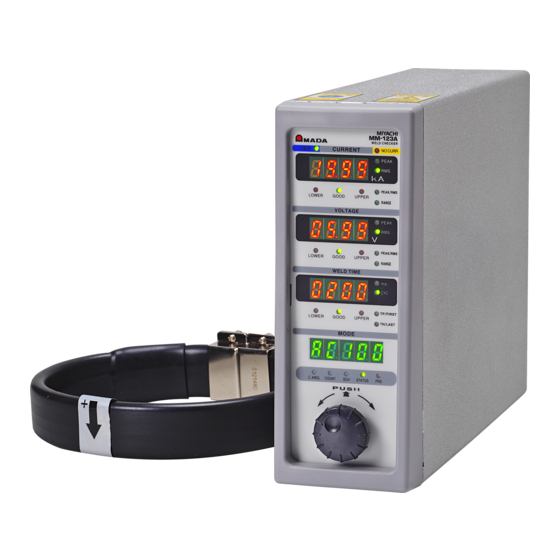
- Page 11 MM-123A 4. Name and Functions of Each Section (1) Front ⑪No-current LED ⑫Peak current ①ISO17657-compliant measurement LED mode LED ⑬Effective current ②Current display measurement LED ⑭Current peak/effective selection LED ③Current upper/lower limit ⑮Current range selection judgment LEDs ⑯Peak voltage ④Voltage display measurement LED ⑰Effective voltage measurement LED...
- Page 12 MM-123A ISO17657-compliant mode LED Lights up when the ISO17657-compliant mode is selected. When this LED lights up, the measurement result calculated with the measurement method complied with ISO17657 is displayed in the effective value measurement. Current display Displays the selected measurement results of the current (peak or effective value) and the set value for the current upper/lower limit judgment.
- Page 13 MM-123A Mode selection LEDs Data for the mode whose LED is on is displayed on the mode display. Turn the operation button to select a mode. For details, see [7. (2) Basic Usage of the MM-123A]. Operation button For all operations.
- Page 14 MM-123A If this LED is on in the current measurement mode CAP-S or CAP-L, the TH (time half) time is measured. For details, see [7. (3) h. Selecting TP/TH (in the current measurement mode CAP-S and CAP-L only)]. 4. Name and Functions of Each Section...
- Page 15 MM-123A (2) Rear ①LAN cable connector ②Service connector ③External I/O connector ⑥Toroidal coil/voltage detecting connector ⑦Power supply switch ④Power cable connector ⑧Fuse holder ⑤Grounding terminal 4. Name and Functions of Each Section...
- Page 16 MM-123A LAN cable connector For connection with the LAN cable for the Ethernet communication. Service connector Do not connect anything. External I/O connector For connection with input and output signals from peripheral devices. Power cable connector Connects to the power cable (option) when the single-phase AC power supply (100–240 V) is used.
- Page 17 MM-123A 5. Interface (1) Connection Diagram of the External I/O Signals Description of each pin on the external I/O connector. Input signal is explained as contact input. INT.24V EXT.COM SCH1 SCH2 SCH4 SCH8 SCH16 GATE COUNT RST NO CURR NG RESET SIG COM TRG SIG VOLT SIG...
- Page 18 MM-123A INT.24V NG+24V(-) NG+24V(+) NG-L NG-H NG COM GOOD NO CURR READY COUNT UP 5. Interface...
- Page 19 MM-123A (2) Description of the External I/O Signals Pin No. Name Function Pins 1, 26, 27, and 28 are pins for the INT.24V. Pin 2 is the EXT.COM. Connect pins as follows: When using contacts or NPN transistors (sink type) on a PLC as input signals to the I/O connector, connect either of INT.24V terminals and Pin 2.
- Page 20 MM-123A <Example combination of the SCH number and the SCH pin number> Pin No. Pin No. SCH No. SCH No. ● ● ● ● ● ● ● ● ● ● ● ● ● ● ● ● ● ● ● ● ●...
- Page 21 MM-123A Pin No. Name Function Not used. Input pin for the Measurement stop [GATE] signal. Used for selecting the welding current to measure. Measurement stops while this circuit is closed. In the impulse welding, the stopping interval of the measurement operation by the [GATE] signal is till the end of the impulse welding.
- Page 22 MM-123A Pin No. Name Function Input pin for the No-current detecting [NO CURR] signal. Close the circuit at least 10 ms before the welding current flows, and open it after the welding current flows. If the welding current doesn’t flow while this circuit is closed, it is judged as no-current when the circuit is opened, the no-current LED lights up and the [NG-H] and [NG+24V] signals are output.
- Page 23 MM-123A Pin No. Name Function Input pin for the [NG RESET] signal. If a trouble occurs, rectify the trouble and close this circuit. The [NG] signals are turned off. (See [9. Fault Code List] for fault codes.) If this circuit is closed when the [NG-L], [NG-H], [GOOD], [NG+24V] or [NO CURR] signal is hold, the hold status is canceled.
-
Page 24: Error Output]
MM-123A Pin No. Name Function The circuit between Pins 37 and 40 is output pin for the [NG] or [NG-L] NG‐H signal. Function is switched by the system setting. For details, see [7. (5) h. System Setting (1) Upper/lower limit NG‐L judgment output operation and (2) Error output]. - Page 25 MM-123A Pin No. Name Function The circuit between Pins 39 and 40 is output pin for the [NG] or [NG-H] NG‐H signal. Function is switched by the system setting. For details, see [7. (5) h. System Setting (1) Upper/lower limit NG‐L judgment output operation and (2) Error output].
- Page 26 MM-123A Pin No. Name Function Output pins for the [GOOD] signal. Close for the fixed time when the measured value is within the range of GOOD the upper/lower limit judgment 43, 44 GOOD function. (For the closed time, see [7. (5) h.
-
Page 27: Connection Of Input Signals
MM-123A (3) Connection of Input Signals a. Connection with Device Having a Contact Input (when Using Internal Power Supply) Connect pins 1 and 2. Internal External 内部 外部 INT.24V 1) INT.24V EXT.24V EXT.COM 2) EXT.COM EXT.COM SCH1 3) SCH1 SCH2 4) SCH2 ・... - Page 28 MM-123A b. Connection with Device Featuring NPN Open Collector Output (when Using Internal Power Supply) Connect pins 1 and 2. Internal External 内部 外部 INT.24V 1) INT.24V EXT.24V EXT.COM 2) EXT.COM EXT.COM 3) SCH1 SCH1 SCH2 4) SCH2 ・ ・ ...
- Page 29 MM-123A c. Connection with Device Featuring PNP Current Output (when Using External Power Supply) Connect the negative side of an external 24 V DC power supply to pin 2. Internal External 内部 外部 EXT.24V No connection 1) 未接続 ⊕ EXT.COM EXT.COM 2) EXT.COM DC24V SCH1...
- Page 30 MM-123A d. Connection with Device Featuring NPN Open Collector Output (when Using External Power Supply) Connect the positive side of an external 24 V DC power supply to pin 2. Internal External 内部 外部 EXT.24V No connection 1) 未接続 ⊕ EXT.COM EXT.COM 2) EXT.COM DC24V...
-
Page 31: Installation And Connections
MM-123A 6. Installation and Connections (1) Installing the MM-123A Place the MM-123A on a stable surface. * Use this Weld Checker in an upright position. To comply with CE, arrange the IEC60947-2-compliant breaker on the upper side of the power supply of the MM-123A. Connect the power cable to the power cable connector on the rear of the Weld Checker. - Page 32 MM-123A (2) Preparations for Measurement – Connection between the MM-123A and Sensors a. Preparing the Toroidal Coil and the Voltage Detection Cable Prepare the toroidal coil to measure the current or the voltage detection cable (SK-1205023) and the relay cable (branching current and voltage) (SK-1201740) to measure the voltage.
- Page 33 MM-123A When measuring voltage As shown below, plug the toroidal coil and the voltage detection cable into the relay cable (branching current and voltage). Plug the relay cable (branching current and voltage) connector into the toroidal coil/voltage detecting connector on the rear panel of the MM-123A. Welding head Relay cable Voltage detection cable...
- Page 34 MM-123A b. Connecting the toroidal coil to the welding machine or arm When fitting the coil, be careful with the following: Keep the toroidal coil’s hooking bracket as far away from the welding machine’s arm (secondary conductor) as possible. ...
- Page 35 MM-123A (3) Grounding the Voltage Detection Cable Ground the FG line of the voltage detection cable in one of the following two ways: a. When the welding head is grounded Relay cable (branching current and voltage) Voltage detection cable FG line b.
- Page 36 MM-123A (4) Connecting the Communication Connector The MM-123A employs the Ethernet communication. Connect the MM-123A and PC/server with a LAN cable (option). For details of communication, see [8. Data Communication]. Example connection 1) To connect the plural MM-123As and a PC, prepare a LAN cable (straight). * Pass the LAN cable through the attached ferrite core twice.
-
Page 37: Basic Operation
MM-123A 7. Basic Operation (1) Startup Connect the toroidal coil. Set the power supply switch on the rear panel to the ON position (– side). After 8 seconds, LEDs light up. The picture below is a state at the time of shipping. - Page 38 MM-123A (2) Basic Usage of the MM-123A The MM-123A has the following five modes. a. C.ANGL (conduction angle) mode b. COUNT (count) mode c. SCH (schedule) mode d. STATUS (status) mode e. PRG (program) mode The mode selection LED indicates the present mode.
- Page 39 MM-123A SCH (schedule) Mode The MM-123A can set 31 schedules of the upper/lower limit of the current, voltage and weld time. In this mode, the present schedule number and step number are displayed, and the schedule number and the step number to measure are set. Measurement cannot be not made during setting.
- Page 40 MM-123A STATUS (status) Mode Displays the present current measurement mode. For details, see [7. (3) a. Selecting the Current Measurement Mode]. PRG (program) Mode Sets and checks the various functions and schedules. To input or change each setting of measurement schedules, preset counter and others, the MM-123A is required to be set in the program mode.
- Page 41 MM-123A Mode selection LED Make settings in the supervisor mode or the operator mode. Supervisor mode setting Operator mode setting 1) Turn the operation button right. The display 1) When the operation button is pressed, the PASS on the mode display disappears. 0 0 0 0 changes to (password...
-
Page 42: Preparation For Measurement
MM-123A (3) Preparation for Measurement To measure the welding current, the following settings of “a” to “d” are necessary. (To measure the peak value, the setting of “g” is unnecessary.) a. Selecting the current measurement mode b. Selecting the schedule number to set c. - Page 43 MM-123A Measurement method Description Unit Min. unit Measures a welding current of a Millisecond 0.1 ms c A P - L capacitor welding machine. (ms) The measurable time is 05.0 to 99.9 *1: The single-phase-AC welding power supply controls the magnitude of the current by setting the time when the welding current does not flow.
- Page 44 MM-123A The set current measurement modes is displayed 5 Y 5 on the mode display and the STATUS of the mode selection LED lights up. 10) Turn the operation button right to turn on the PRG only. 11) Press the operation button for one second. The program mode is cancelled and the PRG is turned off.
- Page 45 MM-123A How to set the frequency Example) When the currently set frequency is 50 Hz A C 0 5 0 Turn the operation button left. Turn the operation button right. Frequency Frequency (normal) (dedicated to our power supply) 1) The right three places blink. The second and third places from the right blink.
- Page 46 MM-123A Selecting the Schedule Number to Set 31 types of measurement schedules can be set. Select the schedule number. When setting the upper/lower limit and the current/voltage range, make sure that the desired schedule number has been set. How to select Turn the operation button to turn on the PRG of the mode selection LEDs.
- Page 47 MM-123A Selecting Peak or Effective Value of Current The current measured in the MM-123A can be displayed as the effective value or the peak value. Select the peak value or the effective value for each schedule number. The value of the effective value display: Effective value from measurement start time (FIRST) to measurement end (LAST).
- Page 48 MM-123A Selecting the Current Range Select the current range for each schedule number. Turn the operation button to turn on the PRG of the mode selection LEDs. Press the operation button for one second while the PRG is on to set the MM-123A in the program mode (supervisor mode).
- Page 49 MM-123A Selecting Peak or Effective Value of Voltage The voltage measured in the MM-123A can be displayed as the effective value or the peak value for each welding schedule. The value of the effective value display: Effective value from measurement start time (FIRST) to measurement end (LAST). See [7.
- Page 50 MM-123A Selecting the Voltage Range Select the voltage range for each schedule number. Turn the operation button to turn on the PRG of the mode selection LEDs. Press the operation button for one second while the PRG is on to set the MM-123A in the program mode (supervisor mode).
- Page 51 MM-123A Setting the Measurement Start Time (FIRST) and the Measurement End Time (LAST) The MM-123A can specify the interval between the welding current start and end and measure its current by setting the measurement start time (FIRST) and the measurement end time (LAST). Set the measurement start time (FIRST) and the measurement end time (LAST) for each schedule number.
- Page 52 MM-123A How to set FIRST Turn the operation button to turn on the PRG of the mode selection LEDs. Press the operation button for one second while the PRG is on to set the MM-123A in the program mode (supervisor mode). Turn the operation button to turn on the SCH of the mode selection LEDs.
- Page 53 MM-123A Turn the operation button to change the blinking number to the desired value. 10) Press the operation button to move the blinking place to the left. Set the desired measurement end time. When the operation button is pressed while the leftmost place is blinking, blinking stops and setting is completed. 11) Turn the operation button to turn on the PRG only.
- Page 54 MM-123A Selecting TP/TH (in the current measurement mode CAP-S and CAP-L only) When measuring the capacitor welding currrent, it is required to select the measured time from TP or TH. Select TP or TH for each schedule number. TP (TIME PEAK) Time duration from the time the welding current starts flowing to the time at max.
- Page 55 MM-123A 11) Turn the operation button to turn on the PRG only. 12) Press the operation button for one second to cancel the program mode. 7. Basic Operation 7-19...
- Page 56 MM-123A (4) Upper/Lower Limit Judgment Function The MM-123A is equipped with the upper/lower limit judgment function for current, voltage and weld time. The upper/lower limit judgment function Sets the upper/lower limit range of the current, voltage and weld time in advance. Judges whether the actually measured current, voltage and weld time are within the set upper/lower limit range.
- Page 57 MM-123A 10) Press the operation button to move the blinking place to the left. Set the desired value for all places. When the operation button is pressed while the leftmost place is blinking, blinking stops and setting is completed. 11) Turn the operation button to turn on the PRG only. 12) Press the operation button for one second to cancel the program mode.
- Page 58 MM-123A Setting the Upper and Lower Limits of the Voltage Set the upper/lower limit for each schedule number. How to set the upper limit Turn the operation button to turn on the PRG of the mode selection LEDs. Press the operation button for one second while the PRG is on to set the MM-123A in the program mode (supervisor mode).
- Page 59 MM-123A Turn the operation button to change the blinking number to the desired value. 10) Press the operation button to move the blinking place to the left. Set the desired value for all places. When the operation button is pressed while the leftmost place is blinking, blinking stops and setting is completed.
- Page 60 MM-123A Setting the Upper and Lower Limits of the Weld Time Set the upper/lower limit for each schedule number. How to set the upper limit Turn the operation button to turn on the PRG of the mode selection LEDs. Press the operation button for one second while the PRG is on to set the MM-123A in the program mode (supervisor mode).
- Page 61 MM-123A Turn the operation button to change the blinking number to the desired value. 10) Press the operation button to move the blinking place to the left. Set the desired value for all places. When the operation button is pressed while the leftmost place is blinking, blinking stops and setting is completed.
- Page 62 MM-123A (5) Settings in the Program Mode Setting the Preset Counter (COUNT) The MM-123A has the preset counter function. The preset counter is common to 31 schedules. The counter proceeds by 1 when the measurement results of all selected measurement items are within the upper/lower limit.
- Page 63 MM-123A Setting the Step Counter When using the step counter function on the welding machine, set the step counter of the MM-123A. The weld count set for each step is common to 31 schedules. When the step number is increased, the value of the upper/lower limit judgment is switched.
- Page 64 MM-123A 12) Set the weld count (the number of welds) for the step set above. Turn the operation button to select the number. When the operation button is pressed, the number is established and the blinking place is moved to the left. Repeat this operation to establish four places.
- Page 65 MM-123A STATUS Setting In the STATUS setting, various common conditions can be set. Settings are common in all measurement schedules. It consists of the following six items. Name Mode display Contents Effective value Original mode Makes setting for the effective value calculation calculation mode method of the measurement interval.
-
Page 66: Original Mode
MM-123A Difference between the Original Mode and the ISO17657-compliant Mode Difference of the effective value calculation method The MM-123A has the following two calculation methods for the effective value. Original mode (arithmetic mean effective value) Calculates the effective value in the measurement interval at a fixed interval and displays the arithmetic mean value as the measurement result. - Page 67 MM-123A Weld time in the original mode a: Weld time till the fall level b: Fall level 10 to 90% c: Current peak value Weld time in the ISO17657-compliant mode a: Weld time till the fall level b: Flow time c: Fall level 10 to 90% d: Current effective value <Difference with the weld time of the MM-122A>...
- Page 68 MM-123A Setting the Various Levels The MM-123A can adjust the measurement start and the end timing by setting the following three parameters. t r i 9 (1) Current trigger sensitivity ( The current trigger sensitivity is a parameter of the sensitivity for detecting the welding current to start measurement.
- Page 69 MM-123A E n d (3) End level ( The MM-123A measures the time until the welding current reaches the end level as a single welding. Also, in the measurement of the AC welding current, the time till the end level is displayed as weld time.
-
Page 70: Measurement Interval
MM-123A Impulse Measurement More than one welding may be performed in one weld sequence. With the impulse measurement function of the MM-123A, you can measure the stage you selected by setting the impulse number. When the impulse number is set to 2: C O O L T I M E C O O L T I M E 1... - Page 71 MM-123A Next measurement preparation time When the current measurement mode is AC, AC*** (frequency), ACSEC, or dccyc, at least 10 ms is required. When dcSEC, dcSSc, CAP-S, or CAP-L, at least 3 ms required. Since it is confirmed that the current is not input, a longer time is required if input.
-
Page 72: Communication Setting
MM-123A Communication Setting The MM-123A is equipped with the Ethernet communication function. It can transmit the measurement data to an external device such as PC and change measurement schedules from an external device. How to set Turn the operation button to turn on the PRG of the mode selection LEDs. Press the operation button for one second while the PRG is on to set the MM-123A in the program mode (supervisor mode). - Page 73 MM-123A IP address: Initial value: 192.168.1.10* Subnet mask: 5 u b Initial value: 255.255.255.0 Default gateway: d F L t Initial value: 192.168.1.100* Port number: P o r t Initial value: 1024* Use [192.168.1.11] or later for the IP address of the personal computer. However, do not set the IP address to the same as the default gateway.
- Page 74 MM-123A 13) When settings of all rows are completed, turn the operation button right with 0 1 0. i P displayed. 14) The address selection screen is displayed again. Perform settings of subnet mask and default gateway in the same manner. 15) Port number setting p o r t Display...
-
Page 75: System Setting
MM-123A System Setting In the system setting, input/output operation, toroidal coil setting, and various functions can be set. The settings in the system setting are common in all measurement schedules. The system setting consists of the following ten items: Item Contents (1) Upper/lower limit HL 1: When the measured value is outside the setting of the... - Page 76 MM-123A Item Contents (6) Cool time When the actual cool time (time when the current does not flow) is shorter than the value set for this parameter in the current c o o L measurement, measurement is performed as a single welding. The time setting is common to 31 schedules.
- Page 77 MM-123A Item Contents (9) Step counter Sets the step counter function on/off. 0: Turns off the step counter function. 5 t E p 0 1: Turns on the step counter function. 5 t E P 1 (The factory setting is StEP0.) For details, see [7.
- Page 78 MM-123A Press the operation button to move to each setting screen. For details see How to set the system items as shown on the next page. C 0 P y - When the operation button is turned right with 5 Y 5 displayed on the mode display, the display returns to 7.
- Page 79 MM-123A How to set the system items The setting items are switched as shown below. Change the setting by the operation button. The set value is displayed at the leading screen. ・Turn the button ・Turn the button ・ Press the button. right and left.
- Page 80 MM-123A Setting the Upper/Lower Limit Judgment when Using the Step Counter Function To use the step counter described in [7. (5) b. Setting the Step Counter], the upper/lower limits of current and voltage must be set in advance. As shown, a state that the upper/lower limits of current and voltage are set for HIGH each step is one schedule.
- Page 81 MM-123A Turn the operation button to turn on the PRG only. 10) Press the operation button for one second. 7. Basic Operation 7-45...
- Page 82 MM-123A Password Setting The MM-123A can select a mode from the supervisor mode and the operator mode by setting a password. By selecting the operator mode, you can prevent schedules from being changed by mistake. The differences are as follows: Operation contents Supervisor mode Operator mode...
- Page 83 MM-123A P A 5 5 Turn the operation button to display on the mode display. When the operation button is pressed, the current password is displayed on the mode display. The initial value is “0000.” Press the operation button. The rightmost place blinks. Turn the operation button to change the value.
- Page 84 MM-123A (6) Checking Settings and Initializing Checking the Setting and the Previously Measured Value Press the operation button twice (within 0.5 ms) to check the present setting and the value measured previously. If the welding current flows during this status, the MM-123A returns to the measurement operation.
- Page 85 MM-123A 12) The TP/FIRST (measurement start) LED lights up. The setting of measurement start for the schedule number displayed presently or the time of TP measured previously is also displayed on the current display. (In the current measurement mode CAP-S or CAP-L, the measured value of TP time is displayed.
-
Page 86: Data Communication
MM-123A 8. Data Communication Monitoring data can be loaded from the MM-123A into the external PC. Also, schedule settings can be written from the external PC into the MM-123A. (1) Data Transfer Item Description System Ethernet IEEE 802.3-compliant (10BASE-T/100BASE-TX protocol TCP/IP) Character code ASCII Checksum data... - Page 87 MM-123A [IP address setting] Set the IP address of the personal computer. The IP address of the MM-123A has been set to [192.168.1.10] at the factory. Use [192.168.1.11] or later for the IP address of the personal computer. However, do not set the IP address to the same as the default gateway.
- Page 88 MM-123A Click the [Properties]. Select the [Internet Protocol Version 4(TCP/IPv4)] and click the [Properties]. 8. Data Communication...
- Page 89 MM-123A Input the IP address. Set the IP address as shown below and click the [OK]. Now the IP address setting is completed. Set 1024 to 5000 for the port number. When you change the setting of the MM-123A, turn off the power supply, or disconnect the LAN cable, connect the MM-123A again.
- Page 90 MM-123A (3) Communication Protocol (Single-Directional Communication) Refer to [7. (5) g. Communication Setting] to set the communication method to Ethernet single-directional communication. Data is output one-sidedly from the MM-123A after the welding current has measured and a fault has occurred. a.
- Page 91 MM-123A Item Display Range Length Delimiter Voltage effective value U: Upper limit error judgment G: Normal L: Lower limit error O: Range over error -: No judgment Delimiter Voltage effective value nnnnn 0.000 to 2.000 (2.000kA range) 00.00 to 20.00 (20.00kA range) 000.0 to 200.0 (200.0kA range) Delimiter Unit of Voltage effective...
- Page 92 MM-123A Item Display Range Length Weld time/TP time nnnnnn 0000.0 to 0180.0 (AC) (0.5CYC step) 0000.0 to 1500.0 (AC---) (0.5CYC step) 000000 to 003000 (ACSEC) 0000.0 to 0120.0 (dccyc) (0.5CYC step) 000000 to 002000 (dcSEC) 000.00 to 025.00 (dcSSc) 000.00 to 009.99 (CAP-S) 0000.0 to 0099.9 (CAP-L) Delimiter Unit of Weld time/TP time...
- Page 93 MM-123A *3: When the current measurement mode is dcSEC, dcSSc, ACSEC, dccyc, CAP-S, or CAP-L, the maximum conduction angle is 000 degrees. Communication example) Monitor data of SCH.# 1 and the current measurement mode “AC” is transmitted from the MM-123A.
- Page 94 MM-123A b. Error Data The following data is output when some fault occurs in the measurement operation of the MM-123A. Item Display Range Length Start code Schedule number 01 to 31 Item code Item number Delimiter Step number 0 (Step counter OFF) 1 to 9 (Step counter ON) Delimiter Counter...
- Page 95 MM-123A (4) Communication Protocol (Bi-Directional Communication) Refer to [7. (5) g. Communication Setting] to set the communication method to Ethernet bi-directional communication. Monitor data can be read and schedule data can be read or written according to the command on the host computer side. However, each item cannot be read or written. Data can be read or written in the bi-directional communication of the MM-123A is as follows: a.
- Page 96 MM-123A Communication example) Reading the monitor data “Host computer → MM-123A” #R00S01*[CR][LF] “MM-123A → Host computer” !01S01,0,1,0,00001,-,02.55,kA,G,01.10,kA,G,0.00,V,-,0.00,V,G,0008.0,CYC,-,0000.0,CYC,0 70,deg[CR][LF] 8. Data Communication 8-11...
- Page 97 MM-123A b. Reading and Writing the Upper and Lower Limit Value Data of Current <Reading request data> Commands transmitted from the host computer to the MM-123A is as follows: Item Display Range Length Start code Read code Schedule number 01 to 31 Item code Item number All contents...
- Page 98 MM-123A <Writing request data> Commands transmitted from the host computer to the MM-123A is as follows: Item Display Range Length Start code Write code Schedule number 01 to 31 Item code Item number Delimiter 7 to 17 Same as 6 to 16 of <Output data for reading request> Return code [CR] (0x0d)
- Page 99 MM-123A c. Reading and Writing the Upper and Lower Limit Value Data of Current of Each Step * Used when the step counter function is ON. <Reading request data> Commands transmitted from the host computer to the MM-123A is as follows: Item Display Range...
- Page 100 MM-123A Item Display Range Length STEP2 peak/effective value nnnnn 0.000 to 2.000 (2.000kA range) current upper limit 00.00 to 20.00 (20.00kA range) 000.0 to 200.0 (200.0kA range) Delimiter Unit of Current value Delimiter STEP2 peak/effective value nnnnn 0.000 to 2.000 (2.000kA range) current lower limit 00.00 to 20.00 (20.00kA range) 000.0 to 200.0 (200.0kA range)
- Page 101 MM-123A Item Display Range Length STEP5 peak/effective value nnnnn 0.000 to 2.000 (2.000kA range) current lower limit 00.00 to 20.00 (20.00kA range) 000.0 to 200.0 (200.0kA range) Delimiter Unit of Current value Delimiter STEP6 peak/effective value nnnnn 0.000 to 2.000 (2.000kA range) current upper limit 00.00 to 20.00 (20.00kA range) 000.0 to 200.0 (200.0kA range)
- Page 102 MM-123A Item Display Range Length STEP9 peak/effective value nnnnn 0.000 to 2.000 (2.000kA range) current upper limit 00.00 to 20.00 (20.00kA range) 000.0 to 200.0 (200.0kA range) Delimiter Unit of Current value Delimiter STEP9 peak/effective value nnnnn 0.000 to 2.000 (2.000kA range) current lower limit 00.00 to 20.00 (20.00kA range) 000.0 to 200.0 (200.0kA range)
- Page 103 MM-123A !01S11,1,1,20.00,kA,02.00,kA,20.00,kA,02.00,kA,20.00,kA,02.00,kA,20.00,kA,02.00,kA,20.0 0,kA,02.00,kA,20.00,kA,02.00,kA,20.00,kA,02.00,kA,20.00,kA,02.00,kA,20.00,kA,02.00,kA [CR][LF] 8. Data Communication 8-18...
- Page 104 MM-123A d. Reading and Writing the Upper and Lower Limit Value Data of Voltage <Reading request data> Commands transmitted from the host computer to the MM-123A is as follows: Item Display Range Length Start code Read code Schedule number 01 to 31 Item code Item number All contents...
- Page 105 MM-123A <Writing request data> Commands transmitted from the host computer to the MM-123A is as follows: Item Display Range Length Start code Write code Schedule number 01 to 31 Item code Item number Delimiter 7 to 17 Same as 6 to 16 of <Output data for reading request> Return code [CR] (0x0d)
- Page 106 MM-123A e. Reading and Writing the Upper and Lower Limit Value Data of Voltage of Each Step * Used when the step counter function is ON. <Reading request data> Commands transmitted from the host computer to the MM-123A is as follows: Item Display Range...
- Page 107 MM-123A Item Display Range Length Delimiter STEP2 peak/effective value nnnn 0.00 to 6.00 (6V range) voltage lower limit 00.0 to 20.0 (20V range) Delimiter Unit of Voltage value Delimiter STEP3 peak/effective value nnnn 0.00 to 6.00 (6V range) voltage upper limit 00.0 to 20.0 (20V range) Delimiter Unit of Voltage value...
- Page 108 MM-123A Item Display Range Length STEP6 peak/effective value nnnn 0.00 to 6.00 (6V range) voltage lower limit 00.0 to 20.0 (20V range) Delimiter Unit of Voltage value Delimiter STEP7 peak/effective value nnnn 0.00 to 6.00 (6V range) voltage upper limit 00.0 to 20.0 (20V range) Delimiter Unit of Voltage value...
- Page 109 MM-123A <Writing request data> Commands transmitted from the host computer to the MM-123A is as follows: Item Display Range Length Start code Write code Schedule number 01 to 31 Item code Item number Delimiter 7 to 81 Same as 6 to 80 of <Output data for reading request> Return code [CR] (0x0d)
- Page 110 MM-123A f. Reading and Writing the Upper and Lower Limit Value Data of Weld Time * Used when the current measurement mode is AC, AC---, ACSEC. Dccyc, dcSEC, or dcSSc. <Reading request data> Commands transmitted from the host computer to the MM-123A is as follows: Item Display Range...
- Page 111 MM-123A Item Display Range Length Weld time lower limit nnnnnn 0000.0 to 0180.0 (AC) (0.5CYC step) 0000.0 to 1500.0 (AC---) (0.5CYC step) 0000.0 to 0120.0 (dccyc) (0.5CYC step) 000000 to 003000 (ACSEC) 000000 to 002000 (dcSEC) 000.00 to 025.00 (dcSSc) Delimiter Unit of Weld time lower limit CYC (AC)
- Page 112 MM-123A Item Display Range Length Unit of Measurement end CYC (AC) time CYC (AC---) CYC (dccyc) ms_ (ACSEC) ms_ (dcSEC) ms_ (dcSSc) Return code [CR] (0x0d) Feed code [LF] (0x0a) <Writing request data> Commands transmitted from the host computer to the MM-123A is as follows: Item Display Range...
- Page 113 MM-123A g. Reading and Writing the Upper and Lower Limit Value Data of Weld Time (TP/TH) * Used when the current measurement mode is CAP-S or CAP-L. <Reading request data> Commands transmitted from the host computer to the MM-123A is as follows: Item Display Range...
- Page 114 MM-123A <Writing request data> Commands transmitted from the host computer to the MM-123A is as follows: Item Display Range Length Start code Write code Schedule number 01 to 31 Item code Item number Delimiter 7 to 15 Same as 6 to 14 of <Output data for reading request> Return code [CR] (0x0d)
- Page 115 MM-123A h. Reading and Writing the System Setting Data <Reading request data> Commands transmitted from the host computer to the MM-123A is as follows: Item Display Range Length Start code Read code Schedule number Item code Item number All contents Return code [CR] (0x0d)
- Page 116 MM-123A Item Display Range Length Measurement frequency 030: 050.[Hz] display 031: 053.[Hz] display 032: 056.[Hz] display 033: 059.[Hz] display 034: 063.[Hz] display 035: 067.[Hz] display 036: 071.[Hz] display 037: 077.[Hz] display 038: 083.[Hz] display 039: 091.[Hz] display 040: 100.[Hz] display 041: 111.[Hz] display 042: 125.[Hz] display 043: 143.[Hz] display...
- Page 117 MM-123A Item Display Range Length End level nnnn 01.5 to 15.0 Delimiter Unit of End level Delimiter Flow time setting 0: Flow time OFF setting 1: Flow time ON setting Delimiter Current trigger level 01 to 99 Delimiter Col sensitivity setting Fixed to 0 Delimiter Coil conversion factor setting...
- Page 118 MM-123A #W00S20,00000,6,0,050,001,ms_,70,%,0010,ms_,0.5,s,05.0,%,0,90,0,227.0,mV/kA [CR][LF] “MM-123A → Host computer” (sent for check when the written data is within the range.) !00S20,00000,6,0,050,001,ms_,70,%,0010,ms_,0.5,s,05.0,%,0,90,0,227.0,mV/kA [CR][LF] 8. Data Communication 8-33...
- Page 119 MM-123A Reading and Writing the Counter Data of Each Step Used when the current measurement mode is AC, AC---, ACSEC, dccyc, or dcSEC and the step counter function is ON. <Reading request data> Commands transmitted from the host computer to the MM-123A is as follows: Item Display Range...
- Page 120 MM-123A Item Display Range Length STEP9 count nnnn 0000 to 9999 Return code [CR] (0x0d) Feed code [LF] (0x0a) <Writing request data> Commands transmitted from the host computer to the MM-123A is as follows: Item Display Range Length Start code Write code Schedule number Item code...
- Page 121 MM-123A Reading and Writing the I/O Setting Data <Reading request data> Commands transmitted from the host computer to the MM-123A is as follows: Item Display Range Length Start code Read code Schedule number Item code Item number All contents Return code [CR] (0x0d) Feed code...
- Page 122 MM-123A <Writing request data> Commands transmitted from the host computer to the MM-123A is as follows: Item Display Range Length Start code Write code Schedule number Item code Item number Delimiter 7 to 13 Same as 6 to 12 of <Output data for reading request> Return code [CR] (0x0d)
- Page 123 MM-123A k. Reading and Writing the Communication Setting Data <Reading request data> Commands transmitted from the host computer to the MM-123A is as follows: Item Display Range Length Start code Read code Schedule number Item code Item number All contents Return code [CR] (0x0d)
- Page 124 MM-123A Item Display Range Length Default gateway 000 to 255 Space 000 to 255 Space 000 to 255 Space 000 to 255 Delimiter Port number nnnn 1024 to 5000 Return code [CR] (0x0d) Feed code [LF] (0x0a) Communication example) Reading the communication setting data “Host computer →...
-
Page 125: Fault Code List
MM-123A 9. Fault Code List The MM-123A lets you know the occurrence of troubles by lighting up LEDs or displaying fault codes. Fault code Cause Measures (Display name) • Trouble of the flash memory Depress the operation button to reset the error. - Page 126 MM-123A Fault code Cause Measures (Display name) Check the current range and voltage range settings. The measured welding current Also, check whether the welding EEEE or torch voltage/weld time has power supply is working normally. (Current, voltage, exceeded the measurable * For current and voltage, the peak time display) range.
-
Page 127: Measurement Specification
MM-123A 10. Specifications (1) Measurement Specification Target Specification 0.100 to 2.000 kA Measurement 01.00 to 20.00 kA range 010.0 to 200.0 kA <Current measurement mode> ・ AC (50 Hz, 60 Hz) Measurement accuracy ±0.0 cycle 000.5 to 150.0 CYC (50 Hz), 000.5 to 180.0 CYC (60 Hz) ・... -
Page 128: Specification
MM-123A Target Specification Maximum value (peak value) within the current flow time or RMS in the interval from the start to end of the measurement RMS depending on the measurement mode CYC mode: Arithmetic mean RMS every half-cycle (original mode) RMS of all measurement range (ISO17657-compliant Measurement mode) - Page 129 MM-123A Target Specification Peak current RMS current (ISO17657-compliant mode) Average RMS current (Original mode) Peak voltage RMS voltage (ISO17657-compliant mode) Measured Average RMS voltage (Original mode) value display Conduction angle Weld time Weld time TP Weld time TH Flow time Weld count (Good count) Impulse number: 0 to 9 (31 schedules) Only the pulse of the set number set is measured.
- Page 130 MM-123A Target Specification The function can be selected from preset counter and the step counter. Preset counter Good counter: 00000 to 99999 (When 00000 is set, the counter function is disabled. The counter proceeds by 1 when all measurement results are within the upper/lower Counter limit.) Step counter...
- Page 131 MM-123A (2) Specification of the MM-123A Item Specification Display contents Current, voltage, time External data output Ethernet (TCP/IP) Number of schedules 31 schedules Rated input voltage 90–250 V AC (50/60 Hz) or 24 V DC ±10% Power consumption 12 W max. Operating ambient 0–45°C temperature...
- Page 132 MM-123A 11. Calibration Regular calibration is required to maintain the MM-123A performance. Calibration is conducted at our facility. For calibration, please send your toroidal coil together with the MM-123A. Depending on the operating environment, the extent of deterioration varies from one MM-123A to another. Therefore, the MM-123A must be calibrated together with the toroidal coil as a set.
-
Page 133: Outline Drawing
MM-123A 12. Outline Drawing (1) Body (Dimensions in mm) 12. Outline Drawing 12-1... - Page 134 MM-123A (2) Drawings for Mounting Bracket (Dimensions in mm) a. Front and Rear Mounting (30) φ4.5 b. Right and Left Mounting φ4.5 12. Outline Drawing 12-2...
- Page 135 MM-123A Index Accessories ............3-1 Password Setting ..........7-46 Calibration ............11-1 Rear................4-5 Communication Setting ........7-36 Specifications ............10-1 Data Communication ..........8-1 Startup ..............7-1 Disposal ..............1-4 System Setting ............. 7-39 Fault Code List ............9-1 toroidal coil .............6-2 Front ..............
Need help?
Do you have a question about the WELD CHECKER MM-123A and is the answer not in the manual?
Questions and answers