Page 1
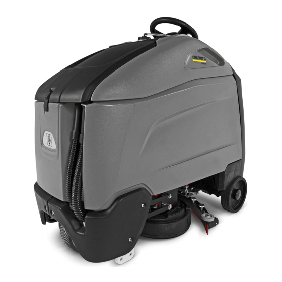
Operating Instructions (ENG) MODELS: CS26 1.006-150.0 CSC26 1.006-151.0 CSM26 1.006-158.0 CSCM26 1.006-159.0 CS26SP 1.006-152.0 CSC26SP 1.006-153.0 CSM26SP 1.006-160.0 CSCM26SP 1.006-161.0 Prior To Serial Number (Ref No 5) * See Serial number page or call manufacturer. Read these instructions before using the machine. 86367610-AM 10/14/16...
Warranty Registration Thank you for purchasing a Windsor product. Warranty registration is quick and easy. Your registration will allow us to serve you better over the lifetime of the product. To register you product go to: www.windsorind.com/WarrantyRegistration.aspx...
Table of Contents Machine Data Label / Overview ....2 To Repair or Replace Vacuum Motor ... 47 Drive Motor .
Page 4
How To Use This Manual This manual contains the following sections: The SAFETY section contains important information regarding hazardous or unsafe practices of the • How to Use This Manual machine. Levels of hazards are identified that could • Safety result in product damage, personal injury, or severe •...
Safety IMPORTANT SAFETY INSTRUCTIONS When using this machine, basic precaution must always be followed, including the following: READ ALL INSTRUCTIONS BEFORE USING THIS MACHINE. To reduce the risk of fire, electric shock, or injury: Use only indoors. Do not use outdoors or expose to rain. Use only as described in this manual.
Page 6
Safety MESURES DE SÉCURITÉ IMPORTANTES Lors de l'utilisation d'un appareil à batteries, il est nécessaire de respecter systématiquement des mesures de sécurité de base, comme suit: PRENEZ NOTE DE TOUTES CES MESURES AVANT D'UTILISER CETTE MACHINE. Pour réduire les risques d'incendie, de chocs électriques, ou de blessures: N'utiliser cette machine qu'en intérieur.
Safety The following symbols are used throughout this guide as indicated in their descriptions: HAZARD INTENSITY LEVEL There are three levels of hazard intensity identified by signal words -WARNING and CAUTION and FOR SAFETY. The level of hazard intensity is determined by the following definitions: WARNING - Hazards or unsafe practices which COULD result in severe personal injury or death.
Page 8
Safety Les symboles ci-dessous sont utilisés à travers ce manuel comme illustré dans leurs descriptions: DEGRÉS DE RISQUES EN CAS DE DANGER Il existe trois degrés de risques identifiés par les termes signalétiques -AVERTISSEMENT et ATTENTION et POUR VOTRE SÉCURITÉ. Le degré de risque est défini de la manière suivante: AVERTISSEMENT - Dangers ou méthodes dangereuses qui POURRAIENT provoquer de graves blessures ou entraîner la mort.
Safety Safety Label Locations These drawings indicate the location of safety labels on the machine. If at any time the labels become illegible, promptly replace them. EMPLACEMENT DE L'ÉTIQUETTE DE SÉCURITÉ REMARQUE : Ces dessins indiquent l'emplacement des étiquettes de sécurité sur la machine. Si, à tout moment, les étiquettes deviennent illisibles, contactez votre représentant autorisé...
Operations Technical Specifications ITEM DIMENSION/CAPACITY Nominal power 1800 W Rated Voltage 36 Volts DC Rated Amperage 50 amps Batteries 3 X12 Volt 205-234 AH @ 20 hr. rate Battery Compartment Dimensions 21 in. x 16 in. x 17 in. tall (533mm x 406mm x 432mm) Scrub Brush Motors - Disk Machine 2 x.5 HP (350 W) Scrub Brush Motors - Cylindrical Machine...
Page 11
Operations ITEM MEASURE Height 50.0 inches (1270 mm) Length 56.1 inches (1425 mm) Width without squeegee 29.5 inches (749 mm) Width of squeegee - Disk Machine 32.7 inches (830 mm) Width of squeegee - Cylindrical Machine 33.5 inches (850 mm) Width of scrub path 26 inches (660mm) WIDTH...
Operations How This Machine Works The function of the recovery system is to vacuum the soiled water back into the recovery tank. The recovery The Chariot® is a battery powered, self-propelled, hard system consists of the squeegee, vacuum motor, float floor scrubber intended for commercial use.
Operations Drive Controls 1. Key Switch 2. Emergency Stop/Brake Switch 3. Directional Control / Drive Reset Switch 4. Throttle Pedal 5. Horn Button 6. Steering Wheel 7. Speed Control 8. Battery Discharge Indicator 9. Hour Meter 1. KEY SWITCH Controls the power for machine functions. To turn the machine power on, rotate key clockwise.
Page 16
Operations 4. THROTTLE PEDAL Controls the speed of the vehicle within the speed control setting selected. Pressing the pedal causes the machine to travel in the direction selected by the Directional Control Switch. To increase speed, increase pressure on the pedal. To decrease speed, decrease pressure on the pedal.
Page 17
Operations 8. BATTERY CHARGE LEVEL INDICATOR Indicates the charge level of the batteries. The meter display is divided into 10 bars. Bars illuminated on the far right indicate full charge. Bars flashing near the left side indicate the batteries should be recharged. Further operation of the machine could damage the machine or the batteries.
Operations Scrub Controls 1. Function Mode Dial The first two positions are for transport only. See drive controls section. A1 - Daytime cleaning/light cleaning This mode is used for light cleaning. In this mode the machine will propel at a maximum of medium speed. The scrub deck will automatically lower to a lower down pressure setting.
Page 19
Operations A4 - Heavy scrub level cleaning This mode is used for heavy level cleaning. In this mode the machine will propel at a maximum of slow speed. The scrub deck will lower to a heavy down pressure. The water will flow at a high rate. The vacuum will flow at a high rate.
Operations Machine Operation Filling Solution Tank FOR SAFETY: Before leaving or servicing Pre-Run Machine Inspection machine; stop on level surface, turn off machine and remove key. Do a pre-run inspection to find possible problems that could cause poor performance or lost time from break- 1.
Operations Optional Chemical Metering System If the machine is allowed to stand in neutral with the scrub deck down, the solutions flow stops and brush 1. Fill chemical container and place into console motors stop. If either forward or reverse travel is recess.
Operations To Begin Scrubbing NOTE: The solution flow can be adjusted up or down approximately 10 percent by changing the dip switch settings on the control board. The dip switches are located on the left side of the control board, mounted on the lower control panel.
Operations Solution Tank brushes down to further loosen soil. The additional application of solution will further assist the difficult 1. Remove the recovery tank lid. cleaning job. 2. Pull the solution drain hose from its mounting FOR SAFETY: When using machine, go slow on pocket.
Operations Squeegee Disk 1. Squeegee Handle The squeegee handle holds the squeegee in place. 2. Squeegee Hose and Tube The squeegee hose and tube carry the recovered solution to the recovery tank. 3. Squeegee Wheels The squeegee wheels support the squeegee at the correct height and angle to automatically obtain optimum suction.
Operations Squeegee - Cylindrical 1. Squeegee Knobs The squeegee knobs hold the squeegee in place. 2. Squeegee Hose and Tube The squeegee hose and tube carry the recovered solution to the recovery tank. 3. Squeegee Wheels The squeegee wheels support the squeegee. The height can be adjusted by turning the knobs. 86367610 Chariot CS26...
Maintenance Service Schedule BEFORE EACH AFTER EACH MAINTENANCE WORK PERIOD WORK PERIOD Check water level of batteries after charging; add distilled water if necessary. (Wet cell only) Check that recovery lid seals tightly. Visually check for damaged or worn wheels. Check brushes or pads for proper installation.
Page 29
Maintenance Batteries (Wet Cell Only) The batteries provide the power to operate the Wear eye protection and protective clothing when machine. The batteries require regular maintenance to keep them operating at peak efficiency. working with batteries. The machine batteries will hold their charge for long periods of time, but they can only be charged a certain number of times.
Page 30
Maintenance Checking Battery Specific Gravity Charging Batteries Use a hydrometer to check the battery specific gravity. When servicing machine, avoid contact with battery acid. Lors de l'entretien de la machine, évitez tout contact avec l'acide de batterie. Batteries emit hydrogen gas. Explosion or fire can result.
Page 31
Maintenance Use a 36 volt, 20 amp maximum output DC charger FOR SAFETY: When charging, connect the charger which will automatically shut off when the batteries are to the batteries before connecting the charger to fully charged. the AC wall outlet. Never connect the charger to the AC wall outlet first.
Maintenance Changing Batteries Stop the machine in a clean area next to the charger. Turn off machine. FOR SAFETY: Before leaving or servicing the machine; stop on level surface, turn off machine and remove key. 1. Remove the rear cover. 2.
Maintenance Onboard Charger (Optional) Circuit Breaker must be off before unplugging batteries. Onboard Charger Programming For machines equipped with optional on-board charger. When replacing batteries, charger programming changes may be required. If replacing batteries with same type, (e.g. maintenance free batteries with main- tenance free) no programming is required.
Maintenance Squeegee Blades To Replace or Rotate Squeegee Blades - Disk The front squeegee blade allows solution to pass through channels in the blade into the squeegee 1. With the squeegee in the up position, turn key assembly while maintaining vacuum to provide lift. The switch "OFF".
Maintenance Scrub Brushes There are four different types of brushes available to cover applications from cleaning heavily soiled floors to polishing. A pad driver is also available to take advantage of the many cleaning pads on the market. Please refer to the following to assist in selecting the proper brush or pad for the work at hand.
Maintenance Replacing or Installing Scrub Brushes - NOTE: Damage to driver or brush could occur if not securely attached. Disk FOR SAFETY: Before leaving or servicing the machine; stop on level surface, turn OFF machine and remove key. 1. Turn machine power off. 2.
Maintenance Brush Motor Carbon Brush Replacement 1. Scribe alignment mark on motor barrel to motor cap. Remove two bolts. Do not use a pressure washer to clean around the brush motors. Use tap pressure only. 2. Remove end cap from motor. NOTE: Motors contain two wave washers in cap.
Maintenance Replacing or Installing Scrub Brushes - Cylindrical 1. Turn machine function dial to transport mode, allowing deck to return to “up” position. Turn the machine power off. FOR SAFETY: Before leaving or servicing the machine; stop on level surface, turn OFF machine and remove key.
Maintenance Actuator Scrub Deck Removal / Scrub Deck Actuator Adjustment Replacement The actuator will need to be adjusted when replaced. FOR SAFETY: Before leaving or servicing machine, To adjust the actuator: stop on a level surface. Turn off machine. 1. While holding actuator barrel to prevent it from 1.
Maintenance Circuit Protection Circuit Breakers 1. MAIN CIRCUIT BREAKER Interrupts the flow of power from batteries in the event of an electrical overload. When the circuit breaker is tripped, it can be reset by pressing the toggle switch. If the circuit breaker continues to trip, the cause of the electrical overload must be corrected.
Maintenance Solution Strainer Located in bottom of tank. Protects system from debris. Solenoid Valve The solenoid valve is mounted on the front of the scrub deck, on left side. The solenoid valve opens and closes to meter the correct amount of solution to the scrub deck.
Maintenance Recovery Tank Float Shut-off When water is no longer being vacuumed from the floor Vacuum Motor Carbon Brushes and the vacuum fan is operating, the ball float has engaged. The vacuum motor will not vacuum water End Cap with recovery tank full. The recovery tank must be drained.
Maintenance Electric Parking Brake Engagement Drive Motor Carbon Brush Replacement FOR SAFETY: Before leaving or servicing machine, stop on a level surface, turn off machine and remove key. Do not use a pressure washer to clean around the motors. Use tap pressure only. Electric Brake Engagement This machine is equipped with an electric parking brake.
Maintenance Transporting Preparation for Loading/Unloading Trailer Before loading or unloading machine from trailer, Pushing Machine remove squeegee, scrub deck, side skirts or side squeegees, Aqua-Mizers and scrub brushes (pads) to The machine may be pushed for short distances at eliminate interference with tie-downs. speeds not to exceed 5 mph.
Maintenance Troubleshooting PROBLEM CAUSE SOLUTION No power to machine Battery disconnected Check all battery cable connections Emergency shut-off activated Reset Battery cables corroded Clean connections Faulty key switch Replace switch On board charger plugged in Unplug and stow cord Main circuit breaker tripped Reset circuit breaker Little or no propel Low battery charge...
Page 52
Maintenance PROBLEM CAUSE SOLUTION Vacuum motor does not run, or Faulty vacuum circuit or switch Check wires connections and motor runs slowly Worn vacuum motor brushes Replace brushes, check commutator Squeegee will not go up/down Faulty circuit or actuator Check wires, connectors and actuator Faulty cables or pulleys Repair/replace cables or pulleys Poor scrubbing performance...
Maintenance Controller Fault Codes ERROR CODE PROBLEM SOLUTION DELUXE THE BATTERY NEEDS CHARGING OR THERE IS A BAD LOW BATTERY VOLTAGE CONNECTION TO THE BATTERY TRACTION MOTOR THE TRACTION MOTOR HAS A BAD CONNECTION, CHECK DISCONNECTED CONNECTIONS TO MOTOR TRACTION MOTOR SHORT THE TRACTION MOTOR HAS A SHORT CIRCUIT TO THE CIRCUIT...
Page 57
Bumper SERIAL NO. PART NO. DESCRIPTION NOTES FROM 86361960 SCR, 5/16-18 X 3.0 PTHMS SS 86361950 SCR, 5/16-18 X 2.0 PTHMS SS 86359000 BUMPER, LEFT, GRAY 86358960 BUMPER, RIGHT, GRAY 86276890 SCREW 5/16-18X3/4 PTHMS SS 86367610 Chariot CS26...
Page 59
Console SERIAL NO. PART NO. DESCRIPTION NOTES FROM 86005620 NUT, 1/4-20 X .962 WELL 86199840 FLOAT SCREEN CAGE ASSY (SLIP) 86272020 NUT, 8-32 HEXTHIN NYLOCK SS 86361770 WASHER, 1/4 SAE FLAT SS 86361760 SCR, 1/4-20 X 1.25 CARRIAGE SS 86361410 GASKET, SIGHT GLASS DOME 86360770 BRKT, RECOVERY TUBE...
Page 61
Console Mounting SERIAL NO. PART NO. DESCRIPTION NOTES FROM 86360300 BRKT, CONSOLE MT LT 86276490 SCREW 5/16-18 X 5/8 HHCS SS 86010670 WASHER 5/16 FLAT SS 86360290 BRKT, CONSOLE MT RT 86367960 SCR, 5/16-18 X 1.38 HHCS SS 86367250 WASHER, .344ID X 1.13OD X .09T SS 86367610 Chariot CS26...
Page 67
Control Panel Mounting SERIAL NO. PART NO. DESCRIPTION NOTES FROM 86371410 SCR, 10-32 X .75 TMS SS BLK 86172980 SCR, KA50X10,PT OHS,WN1412,PLTD 86367610 Chariot CS26...
Page 71
Drive Mounting SERIAL NO. PART NO. QTY DESCRIPTION NOTES FROM 86366140 M10 X 25MM, FLANGE HH BOLT, GR 10.9 86366130 3/8-16 X 1, FLANGE HH BOLT, GR 8 86364130 ASM, SHAFT DRIVE MOTOR 86361070 BRKT, WIRING, DRIVE UNIT 86218360 GROMMET, 3/4 ID X 7/8 GROOVE 86357870 ASM, BEARING BLOCK, FRT DRIVE COMPLETE...
Page 73
Frame SERIAL NO. PART NO. DESCRIPTION NOTES FROM 86360820 ASSY, MAIN SUPPORT, CS26 86360710 ASM, WHEEL GUARD 86358190 GLIDE, BATTERY TRAY 86357950 PAD, TIP 86277410 SCR, 5/16-18 X 5/8 CARRIAGE SS 86276890 SCREW 5/16-18X3/4 PTHMS SS 86276490 SCREW 5/16-18 X 5/8 HHCS SS 86010670 WASHER 5/16 FLAT SS 86400810...
Scrub Deck - Disk A TORQUE 84 IN/LBS 86367610 Chariot CS26...
Page 81
Scrub Deck - Disk SERIAL NO. PART NO. DESCRIPTION NOTES FROM 86361810 MOTOR ASM, 36VDC 300RPM GEAR 86368290 BRUSH SET, 86361810 MOTOR 86008710 RING 3/4" EXT SNAP H-D 86361580 PLATE, MOTOR MOUNT 86010790 WASHER 3/8 SPLIT LOCK PLTD 86276970 SCREW 3/8-16 X 3/4 HHCS 86279530 WASHER .765IDX1.31ODX.09T SS 86003420...
Page 85
Scrub Deck Lift - Disk SERIAL NO. PART NO. DESCRIPTION NOTES FROM 86365440 PIN, CLEVIS 5/16 X 2.25 PL 86008660 COTTER 5/16" RING 86005630 NUT 3/8-16 HEX NYLOCK THIN SS 86255450 SPRING .96D X 4.0L X.135W 86275510 SCREW 3/8-16 X 4.5" HHCS GR5 86010770 WASHER 7/16ID X1DX.08 FLT SS 86011950...
Scrub Deck Mounting - Disk 86367610 Chariot CS26...
Page 91
Scrub Deck Mounting - Disk SERIAL NO. PART NO. DESCRIPTION NOTES FROM 86276920 SCREW 3/8-16X1 86278910 WASHER,3/8IDX7/8ODSS 86008460 SPACER, .500OD X .391ID X .400 86009050 BEARING 1/2 ID X 11/32L NYLON 86005630 NUT 3/8-16 HEX NYLOCK THIN SS 86361570 LINKAGE, DECK, 1.00 X .25THK 86276470 SCREW, 3/8-16 X 2.25 HHCS SS 86224380...
Page 93
Scrub Deck Mounting - Cylindrical SERIAL NO. PART NO. DESCRIPTION NOTES FROM 86370830 SCREW, 5/16-18 X 2.0, PNH, MS, SS 86370120 SPACER, .32 ID X .75D X .75L, AL 86276890 SCREW, 5/16-18 X .75 PHTRHMS SS 86368240 NUT, 5/16-18, FLGNYLOCK,SS 73031070 SCREW, 5x16 -10.9-P2R (K-In6Rd) 86367610 Chariot CS26...
Page 99
Solution System - Disk SERIAL NO. PART NO. QTY DESCRIPTION NOTES FROM 86280910 HOSE, 1/2ID WIREBOUND X 23" 86366100 VALVE, 36V SOL, 1/2 BARB 86363970 HOSE, 1/2ID WIREBOUND X 8.25" 86362980 ELBOW, 1/4FPT X 1/2BARB 90 DEG NYL 86362970 TEE, 1/4 MPT X 3/8 BARBS, NYL 86264940 CABLE TIE 11.38"...
Page 103
Squeegee - Disk SERIAL NO. PART NO. QTY DESCRIPTION NOTES FROM 86367800 SCR, 1/4-20 X 3.00 CARRIAGE SS 86364090 SCR, 5/16-18 X 2.50 CARRIAGE, SS 86364080 SCR, 1/4-20 X 2.00 CARRIAGE, SS 86363100 SPRING, 2.5" X .66 OD COMP 86363070 PLATE, SLIDE, SQUEEGEE BASE 86006200 PIN, CLEVIS, 5/16 X 1.5 STL ZNPLT...
Page 105
Squeegee - Cylindrical SERIAL NO. PART NO. DESCRIPTION NOTES FROM END PIECE LEFT / RIGHT SPARE PARTS 28852940 RUBBER LIP SET OIL RESISTANT BR- 62732070 BD530,55 62732900 RUBBER LIP SET STANDARD RUBBER LIP SET ANTI STRIPE OIL 62732290 RESISTANT CYLINDER HEAD SCREW M 8X25-A4-70 73061420 ISO 47 73120170...
Squeegee Lift SEE DETAIL 'A' 86367610 Chariot CS26...
Page 107
Squeegee Lift SERIAL NO. PART NO. QTY DESCRIPTION NOTES FROM 86364040 BUSH, PLN,.251 X .313 X .75L 86364030 SCR, 1/4-20 X 2-1/4, GR-8, ZN 86364020 SCR, 1/2 X 1-1/4 SSHLD, SS 86362820 BUSH, PLN,.510 X .750 X .375L 86362310 WASHER, .51 X .89 X .06, UHMW 86362300 BUSH, PLN, .25I X .375 X .50L 86362290...
Page 115
Tank SERIAL NO. PART NO. QTY DESCRIPTION NOTES FROM 86367250 WASHER, .344IDX1.130ODX.09T SS 86366450 GASKET, SOLUTION FILL 86362380 ELBOW, PVC, 3/4M X SOC SCH 40 86361920 TUBE ASM, RECOVERY INLET 86361780 LANYARD, 12" SS 86361770 WASHER, 1/4 SAE FLAT SS 86361760 SCR, 1/4-20 X 1.25 CARRIAGE SS 86360780...
Page 129
Wiring 3 DESCRIPTION IDRIVE CONTROL CPU CONTROL G1-G3 BATTERY 12V BRUSH MOTOR BRUSH MOTOR TRACTION MOTOR VACUUM MOTOR DECK ACTUATOR SQUEEGEE ACTUATOR E STOP KEY SWITCH F/R SWITCH PLATFORM SWITCH WATER SWITCH HORN SWITCH PRIME SWITCH MAIN ROTARY CHEM ROTARY HOUR METER BRAKE WATER SOLENOID...
Page 131
Wiring 4 DESCRIPTION IDRIVE CONTROL CPU CONTROL G1-G3 BATTERY 12V BRUSH MOTOR BRUSH MOTOR TRACTION MOTOR VACUUM MOTOR DECK ACTUATOR SQUEEGEE ACTUATOR E STOP KEY SWITCH F/R SWITCH PLATFORM SWITCH WATER SWITCH HORN SWITCH PRIME SWITCH MAIN ROTARY CHEM ROTARY HOUR METER BRAKE WATER SOLENOID...
Page 133
Wiring 5 DESCRIPTION IDRIVE CONTROL CPU CONTROL G1-G3 BATTERY 12V BRUSH MOTOR BRUSH MOTOR TRACTION MOTOR VACUUM MOTOR DECK ACTUATOR SQUEEGEE ACTUATOR E STOP KEY SWITCH F/R SWITCH PLATFORM SWITCH WATER SWITCH HORN SWITCH PRIME SWITCH MAIN ROTARY CHEM ROTARY HOUR METER BRAKE WATER SOLENOID...
Page 135
Wiring 6 DESCRIPTION IDRIVE CONTROL CPU CONTROL G1-G3 BATTERY 12V BRUSH MOTOR BRUSH MOTOR TRACTION MOTOR VACUUM MOTOR DECK ACTUATOR SQUEEGEE ACTUATOR E STOP KEY SWITCH F/R SWITCH PLATFORM SWITCH WATER SWITCH HORN SWITCH PRIME SWITCH MAIN ROTARY CHEM ROTARY HOUR METER BRAKE WATER SOLENOID...
Chemical Metering Solution System - Disk 86367610 Chariot CS26...
Page 139
Chemical Metering Solution System - Disk SERIAL PART NO. DESCRIPTION NOTES FROM 64290380 FLOWMETRE 86364390 PUMP, CHEMICAL DOSING 40354760 HOSE KIT REPLACEMENT 86363990 BRKT, CHEMICAL PUMP 86363980 HOSE, 5/8ID X .12W CLR X 25" 86363970 HOSE, 1/2ID WIREBOUND X 8.25" 86363960 HOSE, 1/2ID WIREBOUND X 15"...
Chemical Metering Solution System - Cylindrical 86367610 Chariot CS26...
Page 141
Chemical Metering Solution System - Cylindrical SERIAL PART NO. DESCRIPTION NOTES FROM 64290380 FLOWMETRE 86364390 PUMP, CHEMICAL DOSING 40354760 HOSE KIT REPLACEMENT 86363990 BRKT, CHEMICAL PUMP 86363980 HOSE, 5/8ID X .12W CLR X 25" 86363950 HOSE, 1/2ID WIREBOUND X 6.25” 86363940 PAD, CHEMICAL PUMP 86371740...
Suggested Spare Parts SERIAL NO. PART NO. DESCRIPTION NOTES FROM 86161800 LATCH & CONCEALED KEEPER 86362390 CASTER, SWIVEL 2” WHEEL 86359580 BLADE, SQUEEGEE, FRONT 86359570 BLADE, SQEEGEE, REAR 86359590 WHEEL, 2.0 OD X .31 ID X .875 GRY 86360270 GASKET, .188 X .31 X 22.8 86360990 HOSE, 1.5 BLK VAC X 40"...
Need help?
Do you have a question about the Chariot 3 and is the answer not in the manual?
Questions and answers