
Related Manuals for Clarke Strong-Arm GC0915


Summary of Contents for Clarke Strong-Arm GC0915
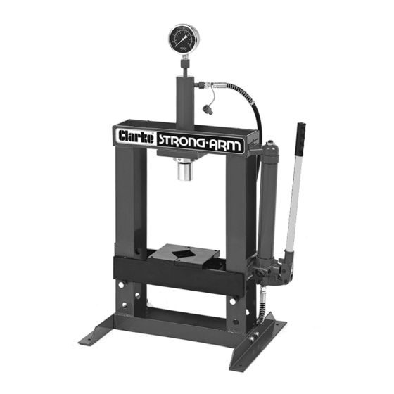
- Page 1 WARNING: Read these instructions before using the machine 10 TONNE HYDRAULIC BENCH PRESS MODEL NO: CSA10BB PART NO: 7614020 OPERATION & MAINTENANCE INSTRUCTIONS GC0915...
-
Page 2: Technical Specifications
GUARANTEE This CLARKE product is guaranteed against faulty manufacture for a period of 12 months from the date of purchase. Please keep your receipt as proof of purchase. -
Page 3: Safety Precautions
SAFETY PRECAUTIONS • During assembly or if the press is moved, always call for the help of an assistant, do not manhandle single-handedly. • Always bolt the press down to a suitably strong bench. • Ensure the press is located on a strong bench with adequate light. •... -
Page 4: Tools Required
• Spanners to suit M6, M8 and M10 nuts/bolts, or an adjustable wrench. • PTFE tape ACCESSORIES A mandrel set (including storage bracket and pressure plate) is not supplied with the press but is available from your dealer as Clarke part no 7615060. INVENTORY 1 x Frame 1 x Pump... - Page 5 1. Attach the feet to the frame, using the nuts, bolts and washers. 2. With the help of an assistant, lift the frame assembly upright and manoeuvre it to its intended location on the workbench. 3. Insert the ram through the hole in the base plate and secure in position using the locking collar.
- Page 6 6. Attach the pump assembly to the frame using the fixing bolts and washers. Fit one bolt first to bear the weight and use the adjustment provided by the upper bolt. • The pump can be installed on either side of the frame but will usually be assembled for a right- handed press operator.
-
Page 7: Hydraulic Pump/Ram Operation
HYDRAULIC PUMP/RAM OPERATION 1. Before using the press, purge any air from the system by opening the release valve by turning it anti- clockwise and pumping several full strokes to eliminate any air bubbles. Tight the release valve before continuing. 2. -
Page 8: Operation
The mandrel can then be pushed into the adaptor where the built-in spring clip will hold it in place. Store the mandrels in their positions on the mounting bracket when not in use. OPERATION WARNING: FAILURE TO HEED THE WARNINGS ON PAGE 3 MAY RESULT IN DAMAGE TO THE EQUIPMENT, OR FAILURE RESULTING IN PROPERTY DAMAGE OR PERSONAL INJURY. -
Page 9: Maintenance
Oil should be level with the mark on the dipstick. If necessary top up with CLARKE hydraulic oil, Part No 3050830. This task is carried out with the ram fully retracted. -
Page 10: Troubleshooting
TROUBLESHOOTING Problem Probable Cause Remedy Pump will not work. Dirt on valve seat/warn Bleed pump unit or have seals. unit overhauled with new seals. Pump will not produce Air-lock in system. Open the release valve pressure. and remove the oil filler Pump feels hesitant plug. -
Page 11: Frame Parts Diagram
FRAME PARTS DIAGRAM Parts & Service: 020 8988 7400 / E-mail: Parts@clarkeinternational.com or Service@clarkeinternational.com... -
Page 12: Parts Lists
PARTS LISTS FRAME PARTS DESCRIPTION DESCRIPTION Pressure Gauge Washer 8mm Nylon Ring Spring Washer M8 Ram Assembly Hydraulic Hose Bed Support Pins Pump Assembly Bolt M6 x 25 Bolt M6x16 Nut M6 Spring Washer M6 Bolt M10 X 25 Washer M6 Washer M10 Upper Collar Spring Washer M10... -
Page 13: Pump Parts Diagram
PUMP PARTS DIAGRAM PART PART PART DESCRIPTION DESCRIPTION DESCRIPTION Pump Housing Release Knob Hand Grip Sealing Washer Connecting Hose Bleed Screw Sealing Washer Hose Connection Cylinder Body Piston Ring Dust Cover O-Ring Piston Steel ball End Housing Sealing Ring Seat O-ring O-Ring Spring... -
Page 14: Ram Parts Diagram
RAM PARTS DIAGRAM PART PART PART DESCRIPTION DESCRIPTION DESCRIPTION Bolt M20 x 25 O-Ring Ram Piston O-Ring O-Ring 40 x 5.3 Grub Screw M6x10 Connector Sealing Ring Washer Gauge Coupling O-Ring 45x2.65 Bolt M8 x 12 Dust Cap O-ring 46.5 x 1.5 Threaded End Connector Nut Distance Piece... -
Page 15: Declaration Of Conformity
DECLARATION OF CONFORMITY Parts & Service: 020 8988 7400 / E-mail: Parts@clarkeinternational.com or Service@clarkeinternational.com...
Need help?
Do you have a question about the Strong-Arm GC0915 and is the answer not in the manual?
Questions and answers