Table of Contents
Advertisement
Advertisement
Table of Contents

Related Manuals for Clarke Metalworker CDP101B


Summary of Contents for Clarke Metalworker CDP101B
- Page 1 SERIAL No....0307...
- Page 2 When disposing of this product, do not dispose of with general waste. It must be disposed of according to law at a recognised disposal facility.
-
Page 3: Table Of Contents
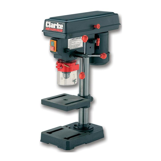
INTRODUCTION Thank you for purchasing your CLARKE - CDP 101B, 13mm bench mounted Drill Press. Before attempting to operate the machine, please read this instruction manual thoroughly, and follow all directions carefully. By doing so you will ensure the safety of both yourself and others around you, and at the same time, you should look forward to long and trouble free service from your Clarke Drill Press. -
Page 4: Safety Precautions
GENERAL SAFETY PRECAUTIONS W ARNING As with all machinery, there are certain hazards involved with their operation and use. Exercising respect and caution will considerably lessen the risk of personal injury. However, if normal safety precautions are overlooked, or ignored, personal injury to the operator, or damage to property may result. KNOW YOUR MACHINE. -
Page 5: Additional Safety Rules For Drill Presses
19. DO NOT STAND ON THE MACHINE. Serious injury could occur if the machine is tipped over. Do not store materials above or near the machine such that it is necessary to stand on the machine to get to them. 20. -
Page 6: Electrical Connections And Wiring Diagram
ELECTRICAL CONNECTIONS Connect the mains lead to a standard, 230 Volt (50Hz) electrical supply through an approved 13 amp BS 1363 plug, or a suitably fused isolator switch. WARNING! THIS APPLIANCE MUST BE EARTHED IMPORTANT: The wires in the mains lead are coloured in accordance with the following code: Green &... -
Page 7: Preparation For Use
Box of loose parts Chuck Guard assy. Check the parts against the above list and refer to the following diagrams. Should there be any deficiencies or damage, you should contact your CLARKE dealer immediately . Loose Items in Box and Bag... -
Page 8: Description Of Parts
Remove all traces of preservative from the components with paraffin or a good quality solvent, and wipe all parts thoroughly with a clean dry cloth. Apply a coating of wax paste or light oil, to the table, column and base, to prevent rust. Take the necessary precautions when lifting components, considering their weight. -
Page 9: Assembly
ASSEMBLY CAUTION! IT IS ADVISED THAT ASSISTANCE BE USED WHEN ASSEMBLING THIS MACHINE. A. Column to the Base. Fig. 1 Bolt the column assembly to the base with the three M8 screws provided. NOTE: Ideally, the base with column attached, should be firmly bolted to a workbench, prior to the assembly of other components. - Page 10 D. Chuck Guard Assembly Slide the Chuck Guard over the Quill Shaft and nip up the pinch bolt, temporarily, with the pinch bolt facing the front (see fig.4). Ensure the Quill Shaft/Spindle is at the top of its travel. NOTE: This operation should be carried out before the chuck is installed. E.
-
Page 11: Settings And Adjustments
H. Assembling the Depth Stop Assy. Slide the end of the threaded rod through the bracket on the side of the head and through the hole in the Guard Collar. (It may be necessary to turn the collar slightly to line up the hole). Secure with the nut provided, from beneath, thereby locking the Depth Stop to the Guard Collar and hence the Spindle. -
Page 12: Drill Speed Table
2. Spindle Depth Stop (All references are to Fig. 7) On the left side of the drill head, is the Spindle Feed (or Depth Feed) adjuster assembly, which allows the depth of hole to be set. For setting a particular depth, proceed as follows: Lower the Chuck - with the power OFF, until the drill bit contacts the surface of the workpiece, and hold in that position. -
Page 13: Operation
Pulley Cover is firmly closed. It is important that this switch operates correctly at all times, and should be checked as described on page 10. Drill Press Vices, Cross Vices and Clamps, are available from your CLARKE dealer. -
Page 14: Maintenance
If the mains lead is worn or cut, or damaged in any way, it should be replaced immediately. Please refer to the trouble shooting chart on page 15 . If you are unable to rectify any faults, please contact your local dealer or Clarke International Service Division on 020 8556 4443 for assistance. -
Page 15: Trouble Shooting
F) Pulley Cover not closed. G) Micro Switch inoperative. G) Check operation of micro switch, per instructions Page 10. If switch operates correctly but motor fails to start consult your Clarke dealer Drill binds A) Excessive feed pressure A) Apply less pressure in workpiece... -
Page 16: Parts Lists And Diagrams
PULLEY ASSEMBLY Item Description Part No Item Description Part No. Rubber Bushing DD20105012 Spindle Pulley DD13105006 Knob DD16105008 Hex Socket Set Screw DDGB80-85 Pan Head Screw 3040656 Cable Clamp DD16102014 ‘V’ Belt K26 DD13105007 Pan Head Screw M5 3040410 Pulley Cover w/labels DD13105000 Foam Washer DD0805009 Washer Hd. -
Page 17: Head Assembly
HEAD ASSEMBLY Item Description Part No. Item Description Part No. 1 Head w/Roll Pin & trim DD13102001 18 Pan Head Screw M5 DDGB818-85 2 Locknut M8 3040601 19 Sw. Box w/Depth Scale DD13102008 3 Washer DDGB97.2-85 20 Pan Head Screw M5 3040656 4 Hex. - Page 18 QUILL ASSY. BASE & TABLE Item Description Part No Item Description PartNo Quill Gasket DD13303003 Hex. Nut M5 3040608 Stop Rod DD13103005 Ball Bearing BRG60201 Table Support w/scale DD13101004 Quill Shaft DD13103002 Table Spt. Lock Handle DD16101013 Pan Hd. Screw M5 3040411 Column Support DD13101003...
-
Page 19: Specifications
CLARKE dealer SPARE PARTS & SERVICING For Spare Parts and Service, please contact your nearest dealer, or CLARKE International, on one of the following numbers. PARTS & SERVICE TEL: 020 8988 7400 PARTS & SERVICE FAX: 020 8558 3622 e-mail as follows: PARTS: Parts@clarkeinternational.com...
Need help?
Do you have a question about the Metalworker CDP101B and is the answer not in the manual?
Questions and answers