
Subscribe to Our Youtube Channel
Related Manuals for Inficon Modul1000 550-300A


Summary of Contents for Inficon Modul1000 550-300A
- Page 1 O P E R A T I N G I N S T R U C T I O N S T r a n s l a t i o n o f t h e o r i g i n a l jinb80en1-12 (2301) Catalog no 550-300A...
- Page 2 Imprint INFICON GmbH Bonner Straße 498 50968 Köln Germany © Copyright 2022 INFICON GmbH, Köln. This document may only be reproduced with the permission of INFICON GmbH, Köln.
-
Page 3: Table Of Contents
Content User guidelines ............. 1-1 Application of this manual ............... 1-1 Warning and danger symbols ............1-1 Representation conventions ............1-2 Explanation of terms ............... 1-2 Important safety instructions ......... 2-1 Intended use ................... 2-1 Operator requirements ..............2-1 Restrictions of use ................2-2 Hazards under normal use ............. - Page 4 6.9.7 Main menu User authorization ..........6-31 6.9.8 Maintenance work ..........7-1 Maintenance and service at INFICON ..........7-1 General notes on maintenance ............7-1 Maintenance plan ................7-3 Maintenance intervals ..............7-3 Description of the maintenance operations ........7-6 7.5.1...
- Page 5 Disposal ..................8-2 Technical data ............9-1 Device data ..................9-1 9.1.1 Power supply .................. 9-1 9.1.2 Weight / dimensions ............... 9-1 9.1.3 Characteristics ................9-1 9.1.4 Ambient conditions ................. 9-2 Control via the PLC inputs and outputs .......... 9-3 9.2.1 PLC inputs ..................
- Page 6 Content...
-
Page 7: User Guidelines
User guidelines Application of this manual • Please read this manual before using the Modul1000. • Save the manual so that you have it at hand at all times. • If the device is passed on to a third party, this manual must be attached. Warning and danger symbols Imminent threat resulting in death or serious injuries Hazardous situation resulting in potential death or serious injuries... -
Page 8: Representation Conventions
Representation conventions Notice Refers to very important information. Refers to an operation that has to be performed. Refers to a result of a completed operation. Refers to a button to be pressed. • A list is displayed. Explanation of terms Automatic tuning / Mass setting This function adjusts the mass spectrometer so that a maximum sensitivity is achieved. - Page 9 Minimum detectable leak rate The minimum detectable leak rate that the Modul1000 can safely detect (5x10 mbar l/s). MEASURE MEASURE is the measurement range with an inlet pressure of less than 0.4 mbar. The minimum detectable leak rate is < 5 x 10 mbar l/s.
- Page 10 User guidelines...
-
Page 11: Important Safety Instructions
The Modul1000 may only be used for leak testing with the gases helium and hydro- gen. It may only be used in dry rooms and on a dry surface. Only use accessories from INFICON. The intended use also includes: •... -
Page 12: Restrictions Of Use
Restrictions of use Lethal hazard due to explosion • Use the Modul1000 only outside explosively hazardous areas. Danger from hazardous gases Device is not suitable for corrosive, toxic and explosive substances. • Use the device only to detect harmless materials. Hazards under normal use Before you install the Modul1000, read all safety instructions carefully and make sure you understand them correctly. - Page 13 Life threatening hazard from electric shock • Unplug the power cord before opening the Modul1000. Hazard of injury and contamination by toxic gases Use the Modul1000 to detect only harmless substances. The device is unsuitable for toxic, corrosive, microbiological, explosive, radioactive or other harmful substances.
- Page 14 Keep body ´parts away from the inlet flange. Supposed risk • If it is to be assumed that safe operation is no longer possible, put the device out of operation and secure it against unintentional start-up. • Please contact the INFICON service. Important safety instructions...
- Page 15 Notice This can be the case: • if the device shows visible signs of damage, • if a fluid has penetrated the device, • if the device is no longer functions, • after extended storage under unfavorable conditions, • after being subjected to significant strain from transport. Caution Injuries and property damage due to high voltages The electronics of the Modul1000 can be damaged by high voltage.
- Page 16 The Modul1000 can be destroyed if liquid is penetrated. • If liquid has penetrated the Modul1000, do not turn on the Modul1000 and contact the INFICON service. Note Material damage due to aggressive substances The Modul1000 will be destroyed by aggressive substances.
- Page 17 (wet, too cold, too high above sea level). (See technical data!) • If the Modul1000 has been stored in these circumstances, leave it switched off. • Contact the INFICON service. Material damage due to improper transport The Modul1000 can be damaged by improper transport. •...
- Page 18 Important safety instructions...
-
Page 19: Description Of Equipment
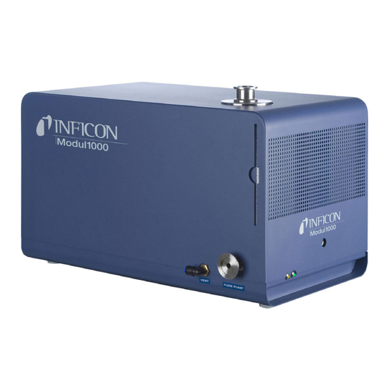
Description of equipment The Modul1000 is a helium leak detector which has been designed to be installed in leak test work stations or integrated machines. The analysis system with turbo molecular pump and a complete control unit are inte- grated in a compact housing. Depending on the set operating mode, the Modul1000 can execute overriding control functions in a leak test system. - Page 20 Fig. 3-2 Right side view and back view Item Description Item Description Inlet flange DN25 KF Vent connection FESTO coupling Loudspeaker / Air inlet Hose 8 mm Openings for unlocking the Mains socket with main switch and cover the cover Mains fuses Recess handles Connection DN25 KF for...
-
Page 21: Interfaces
Interfaces Connectors: LED yellow, LED green CONTROL UNIT (PC) RS232 REMOTE CONTROL PLC IN / AUDIO PLC OUT RECORDER PRESSURE GAUGE ACCESSORIES VALVES, Fig. 3-4 The two 16-pin plug connectors PLC OUT and VALVES are keyed so they cannot be interchanged. -
Page 22: Desktop Operation
3.3.1 Desktop operation The control unit can be placed on even desktops and does not slip. Fig. 3-5 Control Unit for Desktop Operation Item Description Item Description LCD display Button no. 5 Button no. 1 Button no. 6 Button no. 2 Button no. -
Page 23: Remote Control Rc1000
3.3.3 Remote control RC1000 The wireless remote control RC1000 allows the operation of the device from a distance of up to 100 m. The remote control allows the functions START, STOP / VENT (STOP / ventilate), and ZERO (background) to be used, it shows the measured leak rate as a bar graph on the display as a figure or as a diagram (see the technical manual of the RC1000). -
Page 24: Scope Of Delivery
Scope of delivery • Leak detector for helium and hydrogen, Modul1000 • Mains connection cable (country-specific) • Set of spare fuses • Folder with documents • Tools for opening the cover: 8 mm Allen-key • Metering orifice DN25, 2 mm Accessories Accessories Cat. -
Page 25: Set Of Male Connectors For Interfaces
3.5.3 Set of male connectors for Interfaces The connector kit includes the following plugs: PLC IN / AUDIO, PLC OUT, RECORDER, PRESSURE GAUGE, VALVES, ACCESSORIES Description of equipment... - Page 26 Description of equipment...
-
Page 27: Installation
Installation Injury to back due to heavy weight • Carry the Modul1000 with two persons or use some kind of lifting device. Mechanical installation • The Modul1000 is suitable for mounting underneath and above table workstations. • The leak detector may only be operated on a horizontal surface. Material damage from overheated device The device heats up during operation and can overheat without sufficient ventilation. -
Page 28: Electrical Installation
Material damage due to contamination of the vacuum area If objects or particles enter the vacuum area of the device, the device may be dam- aged. • Be careful that objects or particles do not get into the device each time you unplug the connectors. -
Page 29: Electrical Interfaces
4.2.2 Electrical interfaces All the electrical interfaces of the Modul1000 are clearly arranged in a connection panel (See Fig. 3-2). Connectors: LED yellow, LED green CONTROL UNIT (PC) RS232 REMOTE CONTROL PLC IN / AUDIO PLC OUT RECORDER PRESSURE GAUGE ACCESSORIES VALVES, Fig. - Page 30 Sniffer line SL200 or Test chamber TC1000 (ACCESSORIES) The sniffer line SL200 or the test chamber TC1000 can be connected to the connec- tion ACCESSORIES. Use a ferrite on the cable (eg Würth 742 711 31). Lay the cable twice through the ferrite and place it as close as possible to the 14-pin connector.
- Page 31 Fig. 4-2 Jumper XP5 and XP4 Item Description Item Description Pin 1 Pin 3 Pin 2 Analog Recorder output Both of the recorder outputs can be used to record the leak rate, the inlet pressure, and the foreline pressure. The output voltage is updated every 50 ms. Contact Assignment Analog output 1...
- Page 32 With the plug-in bridge field XT1 or XT2, earth or 24V can be connected to the RS232 interface by switching the respective plug-in bridge (pin 2 and 3). Delivery state: XT1 or XT2, pin 1 and 2 bridged "Factory settings (Standard) RS232”. Danger to life due to electric shock! •...
-
Page 33: Vacuum Equipment Connections
4.2.3 Vacuum equipment connections Backing pump The backing pump connection is located on the left front of the device or on the bottom. As an alternative, the pump connection can also be made on the right side in the vacuum version of the Modul1000. Unscrew the connection flange with the open-end wrench AF13 to remodel it and remove the seal. - Page 34 Fig. 4-4 Installing the orifice Ventilation Normally, the DUTs or connected vacuum chambers are vented with ambient air after the test has been completed. If necessary, the DUTs can be ventilated with a different gas (e.g. fresh air, dry air, nitrogen, etc.) to atmospheric pressure. In these cases, the gas supply must be connected to the flood connection (8 mm hose connection) on the left side of the device.
-
Page 35: Operation Modes
Operation modes The following vacuum operating modes are available: • Vacuum, • Commander, • Auto Leak Test. In these operating modes, a partial flow pump can additionally be used. In the sniffing version of the Modul1000 there is also the operating mode: •... -
Page 36: Partial Flow Mode
Partial flow mode In order to increase the effective pumping speed at the vacuum chamber or the DUT, an external partial flow valve can be connected to the valve outlet V20. The increased pumping speed accelerates evacuation processes and the signal response time of the Modul1000. -
Page 37: Auto Leak Test
Auto Leak Test In Auto Leak Test operating mode, components filled with helium can be tested inte- grally in a vacuum chamber. The Modul1000 takes over the entire control of the test sequence. The test sequence is divided into the following steps: Evacuating the vacuum chamber, Measuring the leak rate and subsequently ventilating the vacuum chamber. -
Page 38: Commander Operation
Serial error message The software menu can be used to set a serial error message after a certain number of consecutive measurements with the result "FAIL". The number of consecutive measurements necessary for Modul1000 to issue a serial error message can be set between 2 - 9. -
Page 39: Construction Of A Leak Detection System
5.4.1 Construction of a leak detection system The construction of a leak detection system with the Modul1000 commander function corresponds essentially to that of a conventional integral leak test system. The vacuum chamber is evacuated by the Modul1000, alternatively also in the partial flow mode (Fig. -
Page 40: Test Procedure
Helium filling device The helium filling device consists of the vacuum pump, the valves V30 - V34, a pres- sure measuring point and the helium supply. Valves V30, V31, V32, V33, V34 The test sequence of the Commander Software includes the control of all necessary valves belonging to the helium filling of the DUT. - Page 41 • When set to "OFF": Zero is not performed • When set to "ON": A zero is performed after the time t_B_Zeroverzögerung (zero delay) • When set to: “Stable”: A zero is performed within the time t_B_Zeroverzögerung (zero delay) if the leak rate signal is stable enough to detect a leak in the magnitude of the set trigger level 1.
-
Page 42: Sniffer Mode
Sniffer mode The Modul1000 in the sniffer version can be used as a vacuum as well as a sniffer device. To be able to use it as a sniffer leak detector, the optional sniffer line SL200 must be connected to the "Sniff" connector on the right side of the Modul1000. In the measur- ing mode, the module then sucks a constant gas stream through the sniffer line. -
Page 43: Operation
Operation Switching ON or OFF Switch ON Install the device as described in the Chapter Installation. Connect the mains cable and switch on the device. The power switch and the power cord are located on the rear panel. The run-up starts automatically after pressing the mains switch. During the run-up (... -
Page 44: Controller
Controller The Modul1000 can be controlled via the control unit, via a remote control, via the PLC inputs or via the RS232 interface. The menu item "Control location" is used to select from these options. (See: Main menu Settings Interfaces Control location) Control unit Using the optional control unit, all device functions can be programmed, controlled and read out. -
Page 45: Control Commands
Control commands The following control commands can be sent to the Modul1000 via the corresponding buttons on the optional control unit / remote control, via the PLC control inputs or via the RS232 interface. START When the control unit is connected, the LED in the START button flashes during the evacuation process. - Page 46 Fig. 6-3 Zero function (background suppression) MENU Press the MENU button to display the selection menu on the display. Displaybuttons The function of the eight buttons on the left or right of the display depends on the currently selected menu level. The respective functions are then described in the display.
- Page 47 Fig. 6-4 Example of a numerical input of trigger level 1 To change the trigger threshold from 1.0x10 mbar l/s to 3x10 mbar l/s, press button 2/3 (button no. 3). A sub-menu opens in which the desired value 3 (button 4) can be selected.
-
Page 48: Display
Display The display shows measured values, operating modes, device parameters and their values as well as the functions of the eight buttons on the left and right of the display. Run up After switching on, the Modul1000 outputs various status information via the display. Status line The status line at the bottom of the display outputs the following device information after the Modul1000 has run-up. - Page 49 Fig. 6-5 Evacuate Measuring As soon as the pressure at the inlet of the Modul1000 falls below the set pressure limit, the device changes to measuring mode. Fig. 6-6 Measuring Measurement view Operation...
-
Page 50: Calibration
In the measuring mode two different displays can be selected for the measured value display. • Numeric display with large numbers and as bar display Fig. 6-7 • Graphical display as a function of the measuring time Fig. 6-8 Switching between the numeric display and the graphical display is done with button 8. -
Page 51: Calibration In Vacuum Mode
6.6.1 Calibration in vacuum mode The Modul1000 can be calibrated in different ways. For each calibration the mass spectrometer is adjusted to maximum sensitivity (Auto tune). A distinction is made between internal and external calibration, depending on the test leak used. The calibration can be started in any of the following ways, regardless of the control location: Set control location... -
Page 52: Calibrating In Sniffer Mode
External calibration The external calibration offers the advantage that it takes account of the application- specific measurement conditions. Instead of the test object or at a suitable location of the leak detection system, a suitable calibration leak can be connected to the inlet of the Modul1000. -
Page 53: Calibrate In Commander Mode
• external automatic • external manual For external calibration, a separate test leak is required, which is attached to the chamber. For partial flow mode, an external calibration should always be carried out. Calibration procedure: Manually open test leak of it opens automatically, evacuate, Confirm stable signal with manual calibration, auto tune (adjust to maximum sensitivity),... -
Page 54: Machine Factor
Machine factor The machine factor takes into account the fact that the Modul1000 is used in parallel with a pumping system (partial flow method). Since, in such an installation configuration, only a part of the leakage gas flows through the leak detector, the Modul1000 outputs smaller measured values on the basis of an internal calibration by the partial flow ratio. -
Page 55: Menu Structure
Menu structure Linear / logarithmic scaling Auto / manual display range Time axis Display Contrast Background in standby Lower display limit Operating mode Trigger level 1 Trigger level 2 Trigger level 3 Trigger & Alarms Volume Units Alarm delay Audio Alarm Type Internal automatic Internal manual Calibration... - Page 56 Save under “PARA SET 1” Save under “PARA SET 2” Save under “PARA SET 3” Loading / saving parameters Load default value Load “PARA SET 1” Load “PARA SET 2” Load “PARA SET 3” Settings Calibration request Paging function Contamination protection monitoring Pressure limit for vacuum range Pressure limit for sniffing mode...
-
Page 57: Description Of The Menu Items
Description of the menu items The menu items to which the respective description refers are printed in bold letters. Press the MENU button to display the selection menu on the display. The software menu opens at the menu level at which it was previously exited. Press the MENU button again to exit the software menu. -
Page 58: Main Menu Operating Mode
Contrast You can change the contrast of the display. Changes to the contrast are immediately visible. Under normal conditions a contrast setting of approx. 50 is recommended. If the display was set so bright or dark that menu items cannot be read anymore, the contrast can be set to the factory default as follows: Switch off the Modul1000 and switch it on again During the run-up phase, press buttons 3 and 7 simultaneously until you can read the... - Page 59 Volume The hearing can be damaged by the alarm signal. The alarm level of the Modul1000 can exceed 85dB (A). • Only use the alarm signals for a short time or use ear protection. In the menu item "Volume", the volume of the acoustic signals can be adjusted by pressing the ""...
-
Page 60: Main Menu Calibration (Cal) Vacuum Operating Mode
• Leakage Rate Proportional: The frequency of the audible signal is proportional to the bar graph display. The frequency range is 300 Hz to 3300 Hz. • Setpoint: The pitch is proportional to the leak rate. However, a tone will sound only if the leak rate has exceeded trigger 1. - Page 61 No action is required for manual internal calibration. No inputs are required during the actual calibration phase. In a last step, the Modul1000 saves the newly determined calibration factor. If the newly determined calibration factor deviates by a factor of two from the calibra- tion factor previously determined in the calibration, the acceptance of the new values must be confirmed.
-
Page 62: Main Menu Settings
6.9.6 Main menu Settings 6.9.6.1 Main menu Settings Vacuum settings Purge & Gas Ballast The following functions can be selected in the "Purge & Gas Ballast" menu. • Manual purge • Automatic purge • Manual gas ballast ... - Page 63 Parts number The part counter can be activated in the software menu part numbers and a start value can be determined, from which counting is performed after each test cycle. Reference measurement A reference measurement can be started in this software menu item. ...
- Page 64 Commander pressure thresholds p_A gross leak test Pressure to which the DUT is allowed to sink Factory setting: 900 mbar p_B pump down pressure Pressure to which the DUT is pumped Factory setting: 40 mbar p_C filling pressure Pressure to which the DUT is filled with helium Factory setting: 2000 mbar p_D relaxing pressure Pressure to which the helium is discharged from the DUT...
-
Page 65: Main Menu Settings Zero & Background
6.9.6.2 Main menu Settings Zero & Background Background suppression Inlet area: In addition to the internal background, the background of the inlet area is also subtracted from the measuring signal by pressing the START button. The value has to be determined by means of the function "Background determination inlet area"... - Page 66 The Modul1000 is controlled via the RS232 interface from an external computer. In this operating mode the module cannot be operated via the keyboard. Control interfaces PLC, RS232 and local. Local and PLC The Modul1000 is controlled by the START, STOP and ZERO buttons on the device as well as via the digital inputs.
- Page 67 Zero point: The zero point (pressure value) of the connected sensor can be assigned with the corresponding current or voltage value. Full deflection: The full deflection (pressure value) of the connected sensor can be assigned with the corresponding current or voltage value. ...
-
Page 68: Main Menu Settings Miscellaneous
Example for signal LRlog: Upper limit set to 10 (= 10 V) Scale set to 5 V//decade Lower limit value is thus at 10 (= 0 V) Main menu Settings Interfaces Gas ballast Output • inverted: Output level HIGH with closed gas ballast / purge valve •... - Page 69 Maintenance intervals Resets the maintenance interval of the overall device Maintenance inter- (see Chapter 7 Maintenance work) val device reset Resets the maintenance interval of the turbo molecular Maintenance inter- pump val, TMP reset (see chapter 7 Maintenance work) Via the menu item "Maintenance message for TMP", the ...
- Page 70 The previously stored parameter sets can be loaded and activated with the buttons "Load PARA SET 1" to "Load PARA SET 3". Load default value By pressing the "Load default values" button, one of the four factory parameter sets can be loaded: Default Default...
- Page 71 If the Modul1000 is connected to a wireless remote control RC1000WL, an acoustic signal can be activated, which is heard on the remote control in order to locate and identify it. Contamination protection When this mode is switched on, the Modul1000 will close all valves as soon as the measured leak rate exceeds the limit for the contamination protection.
-
Page 72: Main Menu Info
Maximum evacuation time This menu item is used to determine when a gross leak message is to be made. The gross leak monitoring works on two levels and the threshold can be adjusted when required (factory settings 30 min.). This menu point is especially useful with series tests that always have the same test conditions. -
Page 73: Main Menu User Authorization
Calibration factors The calibration factors for the various masses or operating modes and the machine factor are displayed. Service This menu item is only accessible to INFICON's authorized service personnel. Main menu Info Loggeddata Error list display The last 12 device errors are listed. - Page 74 6-32 Operation...
-
Page 75: Maintenance Work
INFICON is recommended. Maintenance and service at INFICON If you submit a device to INFICON for maintenance or repair, indicate whether the device is free from hazardous substances or has been contaminated. If it is contam- inated, indicate the nature of the hazard. For this purpose, use a form "contamination declaration"... - Page 76 Life threatening hazard from electric shock • Disconnect the leak detector from the mains for all maintenance work! Material damage from pollution • For work on the vacuum system, pay attention to a clean environment and use a clean tool. The Modul1000 has 3 independently running maintenance counters.
-
Page 77: Maintenance Plan
Clean the fan chassis & turbo pump Maintenance schedule legend • I Service level ICustomer • II Service level IICustomer with INFICON training • III Service level IIIAuthorized INFICON service technician • Carry out maintenance as per operating hours or duration •... - Page 78 Replacement filter for fan 200001552 5000 Hour maintenance The 5000 hour maintenance should be carried out by an INFICON service technician or a person authorized by INFICON. The valve drives must be inspected, cleaned and the valve seals or valve caps renewed every 5000 operating hours.
- Page 79 The 2-year maintenance of the turbo molecular pump oil wick cartridge should be carried out by a INFICON service technician or a person authorized by INFICON. Customers who have received a corresponding training from an authorized person can carry out this maintenance within their own responsibility.
-
Page 80: Description Of The Maintenance Operations
Description of the maintenance operations Modifications to Modul1000 which go beyond the normal scope of the maintenance measures may only be carried out by trained personnel. The removal of the device hood is not required for maintenance purposes as described in this Chapter. Replacing a fuse however, requires opening the device. In order to avoid any possible danger with this, the procedure is described below. -
Page 81: Replace Oil Wick Cartridge
Proceed in reverse order when refitting the device cover. When refitting the device cover, make sure that no electrical connections are pinched between the hood and the chassis. To close the device cover, turn the Roto-Lock locks towards the "CLOSE" position. Replace oil wick cartridge The turbo molecular pump is filled with an operating fluid for the lubrication of the ball bearings. - Page 82 Fig. 7-3 sealing cover oil wick cartridge Item Description Item Description Fore-vacuum connection Sealing cover oil wick cartridge Engagement special tool Revision shaft Unscrew the cap on the underside of the turbo molecular pump using a special tool (pin wrench). After the sealing cover has been removed, the oil wick cartridge is accessible.
- Page 83 Fig. 7-4 Replace oil wick cartridge Item Description Item Description Oil wick cartridge O-ring Maintenance work...
-
Page 84: Changing The Fuses
Changing the fuses The replacement of fuses on printed circuit boards is not possible without their removal. The removal without ESD protective measures is grossly negligent and can lead to damage to the device! 7.7.1 Summary of the electrical fuses Designation Technical data Fuse protection for Mains switch... -
Page 85: Replace Mains Fuse
MSV printed circuit card: Designation Technical data Fuse protection for T 2 A 24 V main fuse for MSV board T 3.15 A Anode heater (not used) T 1 A ±15 V;+5 V DC/DC converter M 0.032 A Anode-cathode voltage (85 V) Interface boards: Designation Technical data... -
Page 86: Replacing Interface Board Fuses
Fig. 7-5 Changing the fuses Item Description Item Description Cover flap Fuse link Melting fuse T 6.3 A Groove opening 7.7.3 Replacing Interface Board Fuses The interface board (SSK) contains the fuses for the inputs and outputs on the board. A summary of the fuses and their use can be found under Summary of the electrical fuses. -
Page 87: Parameter Storage (I•Stick) Replacement
Fig. 7-6 Interface board fuses (SSK) Item Description Item Description Interface board SSK I•STICK Parameter storage (I•STICK) replacement The application parameters of the customer are stored on the I•STICK. If a backup device has to be installed, the user parameters can simply be transferred to the backup device by replacing the I•STICK. -
Page 88: Flood Filter Replacement
Fig. 7-7 I•STICK replacement Item Description Item Description I•STICK Mounting screws After the screws have been loosened, remove the I•STICK from the socket and replace it with the I STICK of the defective unit. The installation is carried out in the reverse order. Flood filter replacement The flood filter is checked or exchanged within the scope of the 5000 hours of main- tenance. - Page 89 • To remove the flood filter, disconnect the hose connections from the quick couplings. By pressing the outer ring on the quick couplings, the hose can be pulled off. Refer to Fig. 7-8 for the installation position. Fig. 7-8 Modul1000 replacement flood filter Item Description Item Description Flood filter...
- Page 90 7-16 Maintenance work...
-
Page 91: Transport And Disposal
Transport and disposal Danger of damage The Modul1000 can be damaged by improper transport. • Only transport the Modul1000 in its original packaging. Sending in the device Danger due to harmful substances Contaminated devices could endanger the health. The contamination declaration serves to protect all persons who come into contact with the device. -
Page 92: Disposal
This form can be downloaded Copies: from our website. Original for addressee - 1 copy for accompanying documents - 1 copy for file of sender INFICON GmbH Bonner Str. 498,50968 Cologne, Germany zisa01e1-a Tel: +49 221 3474 2222 Fax: +49 221 3474 2221 www.inficon.com leakdetection.service@inficon.com... -
Page 93: Technical Data
Technical data Device data 9.1.1 Power supply Mains voltage and frequency 100V - 240V ±10%, 50/60 Hz Power consumption < 400 VA Protection type basic unit EN 60529 IP20 U 50E Typ 1 Protection type control unit EN 60529 IP40 U 50E Typ 1 9.1.2 Weight / dimensions... -
Page 94: Ambient Conditions
9.1.4 Ambient conditions For use in rooms Permissible ambient temperature (during operation) +10° C to +40° C 50° F to 104° F Permissible storage temperature 0° C to +60° C 32° F to 140° F Maximum relative humidity 80% at 31° C / 88° F, falling linearly to 50% at 40°... -
Page 95: Control Via The Plc Inputs And Outputs
Control via the PLC inputs and outputs If the Modul1000 is to be controlled via the PLC inputs and outputs, the control loca- tion "PLC", "All" or "Local and PLC" (see chapter, or SB) must be selected. 9.2.1 PLC inputs The electronics of the Modul1000 can be destroyed if the input voltage is too high. - Page 96 START / STOP Flank-controlled input Change from LOW to HIGH: Perform START. Change to LOW: Perform STOP. START Flank-controlled input Change from LOW to HIGH: Perform START STOP Flank-controlled input Change from LOW to HIGH: Perform STOP. If this this input is HIGH for longer that the "Delayed Ventilation" ventilate additionally. VENT Flank-controlled input Change from LOW to HIGH: Flood...
-
Page 97: Plc Outputs
CAL EXT Flank-controlled input Change from LOW to HIGH: Start external manual calibration. CYCLE (Flank-controlled START / STOP input) State-controlled input Change from LOW to HIGH: In the standby state START is executed and the STOP state is executed. GAS BALLAST ON Flank-controlled input Change from LOW to HIGH: The gas ballast valve is opened. - Page 98 Contact Assignment 24V fused with F4 on the interface card (1.6A, maximum current output at this contact together with contact 1 at contact VALVES) NO contact to contact 15 e.g. TRIGGER1 (factory setting) NO contact to contact 15 e.g. TRIGGER2 (factory setting) NO contact to contact 15 e.g.
- Page 99 ERROR Closed if no fault is present. Open if a fault is present. WARNING Closed when there is no warning. Open when there is a warning. CAL ACTIVE Closed when a calibration routine is completed. CAL REQUEST External manual calibration active: Open if external test leak is to be closed.
-
Page 100: The Digital Valve Outputs
TEST FAIL Closed when the result of the Auto Leak test measurement is "FAIL". The digital valve outputs The 16-pin Phoenix connector on the back of the device is labeled "VALVES". Use a ferrite on the cable (eg Würth 742 712 21). Lay the cable twice through the ferrite and place it as close as possible to the 14-pin connector. -
Page 101: Analog Output
Analog output The 4-pin Phoenix pin strip is located on the back of the device and is labeled "RECORDER". The recorder outputs can be used to record the leak rate, the inlet pressure, and the foreline pressure. The values of the recorder output are updated every 50 ms. Both recorder outputs can be set individually for the output of leak rates and pressures. - Page 102 Fig. 9-1 TPR characteristic (P1, P2, recorder output) p1 (input pressure) / p2 (foreline pressure) UL200 The inlet pressure p1 or the foreline pressure p2 is output. This assignment corre- sponds to the logarithmic recorder output of the UL200 leak detector. Pressure logarithmic: U = 1 to 10 V;...
- Page 103 LR exponent The leak rate exponent is output as a step function: U= 1 - 10 V in steps of 0.5 V per decade beginning with 1 V = 1×10 LR log. H. -(11-E) LR=10(V-E)*10 LR = leak rate V = output voltage E = output voltage values rounded down (1V, 2V, 3V, 4V, ...) Voltages between 1V to 1.1V, 2V to 2.1V, 3V to 3.1V etc.
-
Page 104: Connection Assignment
Connection assignment 9.5.1 PLC IN / AUDIO All inputs are optically isolated with opto-couplers. +24V +24V GND 24V SPG GND AUDIO OUT GND 24V Fig. 9-2 External wiring, e.g. PLC with external voltage supply Item Description External, active speaker 9-12 Technical data... - Page 105 +24V +24V GND 24V SPG GND AUDIO OUT GND 24V Fig. 9-3 External wiring, e.g. PLC with internal voltage supply 9-13 Technical data...
-
Page 106: Plc Out
9.5.2 PLC OUT +24V n.c. Fig. 9-4 PLC Out PIN 3 - 12: Relay contacts, max. 60V DC / 25V AC / 1A PIN 13, 14: Semiconductor relay, max. 30V DC / 1A 9-14 Technical data... -
Page 107: Pressure Gage
9.5.3 Pressure Gage Connection of sensors with 4 - 20mA signal Notice Plug in jumpers on interface cards accordingly. +24V, 0.8 A GND 24V 4 … 20mA Input 1 GND 1 Input 2 GND 2 Fig. 9-5 Internal supply +24 V Item Description Pressure sensors... - Page 108 +24V, 0.8 A 4 … 20 mA GND 24V Input 1 GND 1 Input 2 GND 2 Fig. 9-7 External sensor supply 24 V with separate grounding The voltage difference between pin 2 and pins 4 and 5 is ± 4 V. Connection of sensor with 0 - 10V Notice Plug in jumpers on interface card accordingly.
- Page 109 +24V, 0.8 A GND 24V Input 1 GND 1 Input 2 GND 2 Fig. 9-9 Connection with separate grounding The voltage difference between PIN 2 and PIN 4/6 must not exceed ± 4V. 9-17 Technical data...
-
Page 110: Valves
9.5.4 Valves Internal supply +24V +24V Fig. 9-10 Connection example Item Description Valve I max < 0.2 A, maximum 8 pieces Valve I max < 1A 9-18 Technical data... - Page 111 External supply +24V +24V Fig. 9-11 Connection example Item Description Valve I max < 0.2 A, maximum 8 pieces Valve I max < 1A 9-19 Technical data...
-
Page 112: Recorder
9.5.5 Recorder Analog Out1 Analog Out2 Fig. 9-12 Load resistance > 10k Accuracy of the analog output: Final value: 10V: 1.2% from final value Offset ±1% from final value. 9-20 Technical data... -
Page 113: Installation Drawing Of The Control Unit For Rack Installation
Installation drawing of the control unit for rack installation Fig. 9-13 Cutout of the control panel for the installation of the control unit 9-21 Technical data... -
Page 114: Commander Operation
Commander Operation Fig. 9-14 Flowchart 9-22 Technical data... -
Page 115: Warnings And Malfunction Messages
(E026) Overspeed TMP TMP frequency to high Replace TMP incl. TMP converter. Inform INFICON Service. Power supply output voltage of the TMP converter too low. TMP power supply defective Check the output voltage of the Modul1000 24 V power supply Replace TMP with the converter. - Page 116 MC 68 defective. Software problem. EEPROM parameter queue overflow Please contact the INFICON Service! Voltage monitoring input AD24 A/B > 11.5 V External supply (24 V) too high External supply to one of the 24 V outputs of the connector interface card.
- Page 117 Displayed message Description and possible remedy of cause The ambient temperature is too low. Pre-amplifier temperature is too The temperature sensor in the pre-amplifier is defective. low. (<2°C) Faulty MC 68 control board. Signal MVPZN is active on the MSV printed circuit board. 24 V voltage on the MSV board is too low, U <...
- Page 118 Displayed message Description and possible remedy of cause Signal MFAZH is active on the MSV printed circuit board. Nominal value of the anode potential is too high. Brief increase in pressure in the mass spectrometer. Set point of the anode potential Valve impurities cause a high mass spectrometer pressure in the short term.
- Page 119 Displayed message Description and possible remedy of cause The speed of the turbo molecular pump is low after 5 min run-up time. Foreline pressure of the turbo molecular pump is too high. TMP frequency is too low! Turbo molecular pump is defective. TMP converter is defective.
- Page 120 Displayed message Description and possible remedy of cause The inlet pressure of the sniffer line is monitored in sniffing mode. If the inlet pressure drops below a minimum value, the flow rate through the capillary is too low. You can use the menu to adjust the minimum value within certain limits. The factory setting is 0.5 mbar.
- Page 121 Displayed message Description and possible remedy of cause Within the set evacuation time, the pressure threshold of 0.4 mbar has not been Maximum "evacuation time" reached. until measuring mode was DUT has a gross leak. exceeded. Evacuation time is adapted incorrectly to the sample volume. Unable to find the signal maximum within the mass adjustment range.
- Page 122 Displayed message Description and possible remedy of cause Missing or changed parameter in the EEPROM and new software version number determined. EEPROM parameter initialized A software update has been performed and one or more new parameters after software update determined. The message can be acknowledged in this case. The parameter(s) is (are) automatically added.
- Page 123 Displayed message Description and possible remedy of cause Time t2> as the time t_F for reaching the measuring mode "Ultra". Test chamber is leaking. W94 Time until “Ultra” is too long DUT is leaking Incorrect setting for the time t_F (time until measuring mode “Ultra”). Time t1>...
- Page 124 10-10 Warnings and malfunction messages...
-
Page 125: Ordering Information
Ordering Information Description Cat. no. Control unit table drive 551-100 Control unit rack mounting 551-101 Connection line for the control unit, 0.7 m 551-103 Connection line for the control unit, 5 m 551-102 Sniffer line SL200 140 05 Remote control: –... - Page 126 11-2 Ordering Information...
-
Page 127: Appendix
Appendix 12.1 EU Declaration of Conformity 12-1 Appendix... -
Page 128: Declaration Of Incorporation
12.2 Declaration of Incorporation 12-2 Appendix... -
Page 129: Index
Index Backing pump see pump Control • PLC – Inputs and Outputs 6-23 Control location Accessories Control Unit Air filter Control unit 6-17 Alarm delay • Graphical 6-16 Alarms Control units Analog output Cycle 6-24 ASCII 6-16 6-20 Auto Leak Test 6-26 Automatic external calibration Date... - Page 130 Flood filter Mains fuse 7-14 • replacement • replacement 7-11 – material Foreline pressure 7-11 – tool Fore-vacuum Maintenance • Refer to fore-vacuum pump • after 1500 hours 7-10 Fuses • after 2 years • after 5000 hours • TMH071 6-27 Maintenance intervals Gas Ballast...
- Page 131 6-22 Pumping speed START 6-20 Purge Status line STOP Rack • installation Technical data 9-21 – drawing 6-31 Test logs 9-20 Recorder Test system Recorder output 6-26 • analog Time 6-25 • scaling 6-15 Time axis Recorder outputs Trigger Reference measurement Turbo molecular Remote control •...
- Page 132 Index...
- Page 133 Index...
Need help?
Do you have a question about the Modul1000 550-300A and is the answer not in the manual?
Questions and answers