
Related Manuals for Inficon XL3000flexRC


Summary of Contents for Inficon XL3000flexRC
- Page 1 Translation of the original operating instructions XL3000flex, XL3000flexRC Leak Detector Catalog No. 520-200, 520-201 From software version jina83en1-07-(2105) V2.85 (Operating unit)
- Page 2 INFICON GmbH Bonner Strasse 498 50968 Cologne, Germany...
-
Page 3: Table Of Contents
5.2 Connecting the sniffer line ........................ 30 5.3 Mounting the I/O module or bus module (optional)................. 30 5.4 Fasten holder for sniffer line (optional) .................... 31 5.5 XL3000flexRC only: Assemble data cable and CU1000 ................ 32 6 Operation................................ 34 6.1 Switching the device on .......................... 34 6.2 Basic settings............................ 34... - Page 4 Table of Contents INFICON 6.2.3 Selecting a unit for the leak rate .................... 35 6.2.4 Select display unit for pressure.................... 36 6.2.5 Select interface unit for pressure .................... 36 6.2.6 Settings for the XL sniffer adapter .................... 36 6.2.7 Operator types and authorizations.................... 39 6.2.7.1...
- Page 5 INFICON Table of Contents 6.3.4.3 Check the calibration...................... 63 6.3.4.4 Calibration using the external calibration leak test............. 63 6.3.4.5 External calibration with sniffer line SL3000XL .............. 64 6.3.4.6 Automate external calibration with CalMate (optional)............ 65 6.3.4.7 Entering the calibration factor .................... 66 6.3.4.8 Calibration factor sniffing.................... 66 6.3.5 Suppressing gas backgrounds with "ZERO"...
-
Page 6: About This Manual
1 | About this manual INFICON 1 About this manual This document applies to the software version stated on the title page. Product names may occur in the document, which are added for identification purposes only and belong to the respective owner of the rights. -
Page 7: Safety
INFICON Safety | 2 2 Safety 2.1 Intended use The XL3000flex is a helium or hydrogen leak detector for sniffing detection. With the device you locate and quantify leaks on test objects. A test object always contains gas under overpressure. Check the exterior of the test objects for escaping gas using a sniffer line (sniffing method). -
Page 8: Duties Of The Operator
2 | Safety INFICON 2.2 Duties of the operator • Read, observe, and follow the information in this manual and in the work instructions provided by the owner. This concerns in particular the safety and warning instructions. • Always observe the complete operating instructions for all work. -
Page 9: Owner Requirements
INFICON Safety | 2 2.3 Owner requirements The following notes are for companies or any person who is responsible for the safety and effective use of the product by the user, employee or third party. Safety conscious operation • Operate the device only if it is in perfect technical condition and has no damage. - Page 10 2 | Safety INFICON The device contains electric components that can be damaged from high electric voltage. • Before connecting the device to the power supply, make sure that the supply voltage specified on the device is the same as the local power supply.
-
Page 11: Scope Of Delivery
Touch PIN Short instruction 1) XL3000flexRC in standard scope of delivery without data cable and CU1000 control unit. Both are required for the described function. See also "Accessories [} 101]". ► Check the delivery contents after receiving the product to ensure it is complete. -
Page 12: Description
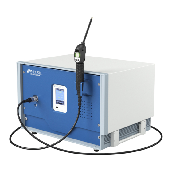
4 | Description INFICON 4 Description 4.1 Function The XL3000flex is a detection device for the tracer gases helium and hydrogen. The device is designed for leak detection with the SL3000XL sniffer line, which is available in different lengths. With this sniffer line, you can detect leaks at a greater distance (high Flow) from the suspected leak if the detection limit has deteriorated and switch to low flow for more accurate localization. -
Page 13: Operation Mode "Sniffing
INFICON Description | 4 4.2 Operation mode "Sniffing" The XL3000flex has been developed exclusively for the "sniffing" mode. For operating you need a sniffer line SL3000XL. It is available in various lengths, see "Scope of delivery and additional equipment". The sniffer line SL3000XL is connected to the connection provided on the front of the device, see "Device setup [} 14]". -
Page 14: Device Setup
4 | Description INFICON 4.3 Device setup XL3000flex: Front view Connection for sniffer line Status LED of the operating unit. SL3000XL Shines: Control unit operates normally Flashes: Display in power saving mode Touchscreen Connection for USB stick Area for fixing a holder for the... - Page 15 LED shows that the sniffer line is supplied with voltage. Interface for a data cable for connection to an external control unit CU1000. See also "XL3000flexRC only: Assemble data cable and CU1000 [} 32]". Area for fixing a holder for the sniffer line...
- Page 16 4 | Description INFICON Back view Filter ventilator inlet Power cable connection Filter ventilator inlet Mounting screws for a profile rail (for mounting the I/O module IO1000 or the bus module, optional) Device power ON/OFF switch Connection "TL" for connection...
- Page 17 INFICON Description | 4 View from below filter fan outputs Rubber feet (4 pieces) Side handles for transportation Transport handles Do not open the device! XL3000flex-Operating-instructions-jina83en1-07-(2105) 17 / 108...
-
Page 18: Sniffer Line Sl3000Xl
4 | Description INFICON 4.4 Sniffer line SL3000XL 4.4.1 Device overview 1 Connection SL3000XL, connection for 2 The status LED indicates the the sniffer line on the front operating status. A permanently lit status LED shows that the sniffer line is supplied with voltage. -
Page 19: Operating Elements On The Handle
INFICON Description | 4 4.4.2 Operating elements on the handle The display of the handle displays part of the information of the main display. Fig. 1: Sniffer line SL3000XL The leak rate is shown as a bar graph and displayed numerically. The unit of measurement is the same as in the main display. -
Page 20: Touchscreen Elements
4 | Description INFICON 4.5 Touchscreen elements 4 5 6 7 Fig. 2: Measurement display Keyboard lock Communication status Operator ZERO Message Tracer gas Operation mode Leak rate with peak hold Graphic representation of the function leak rate and the peak hold... - Page 21 INFICON Description | 4 • Icon disconnected: The device does not communicate with the mass spectrometer module. ► To reset the control unit, press the reset button with the key PIN, see also “Device setup [} 14]“, first illustration. 3 - Operator The registered operator is shown abbreviated.
- Page 22 4 | Description INFICON 9 - Graph Graphic display of the leak rate Q(t). 10 - Leak rate Time axis of the leak rate Q(t). 11 - Button "Favorite 2" You can assign preferred parameters to this key. 12 - Button "Favorite 1"...
-
Page 23: Elements Of The Error And Warning Display
544 x 404 x 358 mm Weight 37.5 kg XL3000flexRC Dimensions (L × W × H) 544 x 404 x 358 mm Weight 36.5 kg Electrical data XL3000flex, XL3000flexRC Power 280 VA Operating voltage 100 - 240 V, 50 / 60 Hz XL3000flex-Operating-instructions-jina83en1-07-(2105) 23 / 108... - Page 24 4 | Description INFICON XL3000flex, XL3000flexRC Main fuse 2x T6,3 A 250 V Protection class IP 30 Overvoltage category Physical data XL3000flex, XL3000flexRC Run-up time 150 s Detectable gases Helium, hydrogen Detectable masses He, H , Mass 3 (e.g. H-D,...
-
Page 25: Factory Settings
INFICON Description | 4 Ambient conditions XL3000flex, XL3000flexRC Permissible ambient temperature (during 10 °C ... 40°C operation) Max. altitude above sea level 2000 m Max. relative humidity ≤ 31°C 80 % Max. relative humidity > 31°C 50 % Storage temperature -20 °C ... - Page 26 4 | Description INFICON Parameter Factory setting Filter ZERO time Filter mode I-Filter Gas percentage in H (M3, He) 5 % H , 100 % M3, 100% He Gas ballast I/O module log ASCII Calibration request Calibration factor VAC/SNIF Mx...
- Page 27 INFICON Description | 4 Parameter Factory setting Machine factor / Sniff factor 1.0 (for all masses) Mass Module on the I/O connection IO1000 Nominal state TMP calibration leak external SNIF 9.9 x 10 calibration leak external VAC 9.9 x 10 calibration leak internal 9.9 x 10...
-
Page 28: Installation
5 | Installation INFICON 5 Installation The structure of the device, see “Device setup [} 14]“. 5.1 Setup CAUTION Risk of injury from lifting the heavy device The device weighs approx. 37 kg and can slip out of your hands. ► Lift and transport the device only with persons who are physically able to do so. - Page 29 INFICON Installation | 5 WARNING Danger from moisture and electricity Moisture entering the device can lead to personal injury due to electric shocks as well as damage to property due to short circuiting. ► Only operate the device in dry environments and only in buildings.
-
Page 30: Connecting The Sniffer Line
5 | Installation INFICON 5.2 Connecting the sniffer line Connect the sniffer line before you start up the device. Connection for sniffer line Align the red marking on the sniffer line plug with the red marking on the socket of the device. -
Page 31: Fasten Holder For Sniffer Line (Optional)
INFICON Installation | 5 ü You have a separately available I/O module or bus module. See also "Accessories [} 101]". ü You have a commercially available DIN-TS35 DIN rail. Place the sniffer leak detector at least 20 cm away on all sides. -
Page 32: Xl3000Flexrc Only: Assemble Data Cable And Cu1000
ð The holder is pulled to the front panel of the device with a magnet on its rear. When not in use, fix the sniffer line in the holder so that it points away from the operator. 5.5 XL3000flexRC only: Assemble data cable and CU1000 32 / 108... - Page 33 Accessories required The XL3000flexRC is delivered in the standard scope of delivery without data cable and CU1000 control unit. Both are required for the described function. See also "Accessories [} 101]" and the operating instructions for the CU1000 control unit.
-
Page 34: Operation
6 | Operation INFICON 6 Operation 6.1 Switching the device on ► Turn on the XL3000flex via the power switch on the back of the device, see “Device setup [} 14]“. ð The system is starting automatically. ð After the start-up, the green LED on the front cover of the XL3000flex lights up. -
Page 35: Setting Date And Time
INFICON Operation | 6 6.2.2 Setting date and time Setting the date Format: DD.MM.YY Control unit Main Menu > Settings > Date/Time > Date LD protocol Command 450 ASCII protocol *HOUR:DATE Setting the time Format: hh: mm Control unit Main Menu > Settings > Date/Time > Time... -
Page 36: Select Display Unit For Pressure
6 | Operation INFICON oz/yr sccm Control unit Settings > Set up > Interfaces > Units (interface) > Leak rate unit SNIF LD protocol Command 432 (sniffing) ASCII protocol Command *CONFig:UNIT:LRSnif 6.2.4 Select display unit for pressure Device of pressure... - Page 37 INFICON Operation | 6 Function of right sniffer Activate or deactivating the right key of the SL3000XL sniffer line (switching between low flow and high flow). Deactivating the key prevents an inadvertent influencing of the measurement. Control unit Settings > Set up > Operation modes > Sniff > Sniffer > Keys >...
- Page 38 6 | Operation INFICON Control unit Settings > Set up > Operation modes > Sniff > Sniffer > LED > Sniffer LED alarm config. LD protocol Command 413 ASCII protocol Command *CONFig:LIGHTAlarm Sniffer beep: Alarm Response by the beep on the sniffer if the trigger value is exceeded.
-
Page 39: Operator Types And Authorizations
INFICON Operation | 6 Control unit Settings > Set up > Operation modes > Sniff > Capillary > Blocked XL > Pressure capillary blocked XL LD protocol Command 455 ASCII protocol Command *CONFig:PRESSXLLow Pressure value XL You set a maximum pressure value in order to detect a disruption in the XL capillary capillary broken (high (high flow, 3000 sccm). -
Page 40: Logging Out The Operator
Calling up factory settings Entering maintenance history The menu "Service" is accessible only to INFICON service staff. Display error The type of error information can be set differently for each operator type. The information Integrator always receives the complete information. -
Page 41: Setting The Audio Alarm
► Set the volume up to a maximum of "12” (XL3000flex). ► Use suitable hearing protection at volume settings above "12". ► With the XL3000flexRC, the actual volume depends on what you plug into the CU1000's headphone jack. Volume of the headphones or active speaker... -
Page 42: Changing The Display Of The Axes
6 | Operation INFICON Control unit Main menu > Settings > Set up > MS module > Ion source > Cathode selection LD protocol ASCII protocol *CONFig:CAThode *STATus:CAThode 6.2.10 Changing the display of the axes The touchscreen grays out the parameters if •... -
Page 43: Changing The Display Of Measured Values
INFICON Operation | 6 6.2.11 Changing the display of measured values Measured value Type of graphic display display Line graph Bar graph Control unit Main menu > Display > Measurement display > Measured view Numeric representation of the measurements Control unit Main menu >... -
Page 44: Automatic Switch-Off Of The Touchscreen
6 | Operation INFICON Control unit Main menu > Settings > Set up > Control unit > Messages > Show warnings 6.2.15 Automatic switch-off of the touchscreen The touch screen can be switched off automatically after a specific time without any operation to save energy. -
Page 45: Selecting The Type Of Expansion Module
INFICON Operation | 6 Favorite 2: Right button Favorite 3: Button at the bottom right of the main menu Volume Flow switching Display settings Check CAL Start/stop AQ Assistant (not applicable to XL3000flex!) Measurement display Gas equivalent ZERO - - - (= nonfunctional) Control unit Main menu >... -
Page 46: Assigning Analog Outputs Of The I/O Module
6 | Operation INFICON 6.2.21 Assigning analog outputs of the I/O module The analog outputs of I/O module IO1000 can with assigned with different measurement value displays. Possible functions: see the following table Control unit Main Menu > Settings > Set up > Interfaces > I/O module >... - Page 47 INFICON Operation | 6 The upper limit (= 10 V) is set via the parameter "Upper limit exponent". The lower value is always 0 (leak rate), which corresponds to 0 V output voltage. The exponent of the upper limit can be set in entire decades, such as 1 x 10...
- Page 48 6 | Operation INFICON 48 / 108 XL3000flex-Operating-instructions-jina83en1-07-(2105)
-
Page 49: Assigning The Digital Inputs Of The I/O Module
INFICON Operation | 6 6.2.22 Assigning the digital inputs of the I/O module The digital inputs PLC-IN 1 ... The available functions can be assigned in any way necessary to the 10 I/O module. – Active signal: typically 24 V –... - Page 50 6 | Operation INFICON Function Flank/state: Description ZERO inactive→ Switch ZERO on. active: Switch ZERO off. active→ inactive: ZERO pulse inactive→ Switching ZERO on or off. active: Delete inactive→ Erase warning or error message / cancel calibration. active: Gas ballast inactive→...
-
Page 51: Assigning The Digital Outputs Of The I/O Module
INFICON Operation | 6 Function Flank/state: Description Internal PROOF inactive→ Start the internal Proof function. In the XL3000flex without function. active: External inactive→ Start the external Proof function. PROOF active: START / STOP inactive→ Activate Start or Stop. impulse active: ZERO update inactive→... - Page 52 6 | Operation INFICON LD protocol Command 263 ASCII protocol *CONFig:PLCOUTLINK:1 (2 ... 8) Functions, assignment of digital outputs: Function State: Description Open open: always open Trigger 1 closed: Value exceeded leak rate threshold Trigger 1 open: Value fell below leak rate threshold Trigger 1...
-
Page 53: Settings For Bus Module Bm1000
INFICON Operation | 6 Function State: Description Measure closed: Measuring (ZERO is possible, all trigger outputs switch depending on the leak rate.) Standby or emission disabled (ZERO is not possible, all trigger outputs will open: return "Leak rate threshold value exceeded".) - Page 54 6 | Operation INFICON Select operation mode (Not applicable for XL3000flex!) (Not applicable for XL3000flex!) Operation mode XL sniffer adapter Control unit Sniffer mode: Main Menu > Functions > Start/Stop LD protocol Command 401 ASCII protocol Command *CONFig:MODE 54 / 108...
-
Page 55: Settings For The Measurements
INFICON Operation | 6 6.3 Settings for the measurements 6.3.1 Select gas type (mass) The machine, calibration and sniff factor are dependent on the configured mass and are saved in the mass spectrometer module. (Hydrogen, forming gas) He or deuterated hydrogen (HD) -
Page 56: Gas Equivalent Selection
6 | Operation INFICON You have a choice of two methods: • To conveniently set the correction factor, use the "Gas equivalent selection [} 56]". There, the correction factor can be selected from a self-defined list, see "Configure gas list [} 56]", or switched back to the tracer gas. -
Page 57: Calculate Equivalence Factor
"Equivalence gas name" and confirm your choice. Then enter the molar mass and viscosity factor of the equivalence gas. For all gases that are not available in the gas library, please feel free to contact INFICON. Make your customer-specific entries in the following windows, which are brought up by the assistant, first "Absolute pressure equivalence gas". -
Page 58: Set Equivalence Factor And Molar Mass
6 | Operation INFICON Dynamic viscosity of test gas (helium or H Dynamic viscosity of the equivalent gas Absolute pressure of the test gas in the test object in bar Absolute pressure of the equivalent gas in the test object in bar For example An air conditioning system is to be checked for leaks. -
Page 59: Setting Setpoints
INFICON Operation | 6 Set your molar mass. In the example for 102: ð If the equivalence factor is not equal to 1 or the molar mass is not set to factory settings, the equivalence factor is displayed both on the calibration result and on the measurement screen. -
Page 60: Calibrating The Device
6 | Operation INFICON Save 6.3.4 Calibrating the device 6.3.4.1 Time and general preferences NOTICE Incorrect calibration because of operating temperature that is too low If the instrument is calibrated immediately after power-on, it may provide incorrect measurement results. ► For optimum accuracy the device should have been turned on at least 20 minutes previously. -
Page 61: External Calibration Configuration And Start
INFICON Operation | 6 Control unit Main Menu > Functions > CAL > Settings > CAL request. > Calibration request Main Menu > Settings > Set-up> CAL request. > Calibration request LD protocol Command 419 ASCII protocol *CONFig:CALREQ (ON,OFF) Calibration warning The warning message Wrn650 "Calibration within the first 20 minutes is not... - Page 62 6 | Operation INFICON ASCII protocol Command *CONFig:CALleak:EXTSniff (for current mass in device selected unit) ► LD and ASCII protocol: The status must be queried via: Command 260 or *STATus:CAL Start calibration. Wait until leak rate signal is tuned and stable.
-
Page 63: Check The Calibration
INFICON Operation | 6 Fig. 5: External calibration with IO1000 using the example of sniffer line SL3000XL, description of PLC inputs and outputs: "Assigning analog outputs of the I/O module [} 46]" 6.3.4.3 Check the calibration To check whether a re-calibration is necessary, check the already existing. -
Page 64: External Calibration With Sniffer Line Sl3000Xl
6 | Operation INFICON Start test: Control unit: Functions > CAL > Test ext. LD protocol: 4, Parameter 5 ASCII protocol: *CAL:PROOFEXT IO1000 compare figure in "External Calibration Configuration and Start". ð Request to "close calibration leak" Sniffer mode: Remove sniffer line from calibration leak. -
Page 65: Automate External Calibration With Calmate (Optional)
In sniffer mode, it is possible to automate calibrations with an external calibration leak. ü The CalMate calibration adapter is mounted on an external INFICON sniffer calibration leak so that the opening in the adapter is directly above the outlet of the calibration leak. -
Page 66: Entering The Calibration Factor
6 | Operation INFICON If you want to perform a calibration, insert the sniffer tip into the calibration opening again and then immediately press the right button on the sniffer line. ð Otherwise the calibration would only be checked again. -
Page 67: Suppressing Gas Backgrounds With "Zero" Functions
INFICON Operation | 6 Mass Calibration factor SNIF XL H2 XL M3 XL He LD protocol Commands 519, 521 ASCII protocol Command *FACtor:CALSniff or *FACtor:CALSXL for the current mass 6.3.5 Suppressing gas backgrounds with "ZERO" functions Unwanted sample gases can be suppressed with ZERO. If ZERO is enabled, the currently measured leak rate value will be interpreted as carrier gas and subtracted from all subsequently measured values. - Page 68 6 | Operation INFICON Deactivating the ZERO Deactivation of the ZERO-key (ZERO-alignment) prevents that the measurement is key on the sniffer influenced inadvertently. Control unit Main Menu > Settings > Setup > Modes > Sniff > Sniffer > Button > ZERO at startup...
-
Page 69: Measuring
INFICON Operation | 6 6.4 Measuring ü The sniffer line SL3000XL is optionally connected to the rear side of the device, see Device setup [} 14]". ü Possible alternatives to the operating possibilities on the device are set up (optional): I/O-Modul or Bus-Modul, see “Accessories [} 101]“. - Page 70 6 | Operation INFICON – Generally select signal filter I-Filter for the operation mode "Sniff". – If the signal filter should simulate the time behavior of older units, then select filter "Fixed" or "2-Zone". I•CAL The leak rates are averaged at time intervals that are optimized for the range of the leak rates.
-
Page 71: Recording Data
INFICON Operation | 6 6.6 Recording data The data is saved as a TXT file. Each TXT file contains the following information: • Date created • Software version • Serial number • Start time • Time stamp (measurement indicates offset in seconds in relation to start time) •... -
Page 72: Copying Measurement Data, Deleting Measurement Data
• "Main Menu > Functions > Data > Recorder > Delete > Delete files” 6.8 Updating the software Software updates from INFICON are installed with the aid of a USB flash drive. The update function of the device can be found under "Functions > Data > Update". -
Page 73: Updating The Software Of The I/O Module
INFICON Operation | 6 ð Do not switch off the device and do not remove the USB flash drive while the software is being updated! Check the version information. Select the "Start" button to start the update. Do not switch off the device and do not remove the USB flash drive while the software is being updated! Follow the instructions on the touchscreen and wait until the update is complete. -
Page 74: Calling Up Information
6 | Operation INFICON Fig. 6: DIP switch on the I/O module 6.9 Calling up information Different information and states of the system can be called up with the info menu. Measurement values • Preamplifier • Environment • TMP Temperature • Electronic •... - Page 75 INFICON Operation | 6 • Calibration, calibration history • TMP error, TMP history • Warnings, active warnings • Maintenance, maintenance history Control unit • Version control unit: Information on the software version • Memory: Information on available memory • Settings: Control unit settings.
- Page 76 6 | Operation INFICON Fig. 7: I/O module (2): Visualized information to the digital inputs Input signal condition Configured function (INV = Function is inverted) Status of the function (active or inactive) • I/O module (3): Visualized information to the digital outputs...
-
Page 77: Display, Save, Load Parameters
INFICON Operation | 6 Fig. 8: Visualized information to the digital outputs Configured function (INV = Output signal condition Function is inverted) Status of the function (active or inactive) • Bus module (1): Information on the bus module • Bus module (2): Information on the bus module, continued 6.10 Display, save, load parameters... -
Page 78: Resetting The Settings
6 | Operation INFICON Loading or saving To save and restore the parameters of the device, you can connect a USB stick to the parameters front of the device. Save parameter: • Main Menu > Functions > Data > Parameters > Save Loading parameters: •... -
Page 79: Warning And Error Messages
The following table displays all the warnings and error messages. It lists possible causes for the malfunction and instructions on how to eliminate these. Please note that work marked with an asterisk must be carried out only by service staff that is authorized by INFICON. Warning Error message... - Page 80 7 | Warning and error messages INFICON Warning Error message Error number Limit values Cause (Wrn) LDS3000 LDS1000 Binary or Protocol ASCII Error (Err) protocol compatibilit y mode LDS1000/ LDS2010 Wrn125 I/O module not connected Connection to I/O module interrupted...
- Page 81 INFICON Warning and error messages | 7 Warning Error message Error number Limit values Cause (Wrn) LDS3000 LDS1000 Binary or Protocol ASCII Error (Err) protocol compatibilit y mode LDS1000/ LDS2010 Wrn240 Voltage +15V out of range +15V too low, IF board or MSB...
- Page 82 7 | Warning and error messages INFICON Warning Error message Error number Limit values Cause (Wrn) LDS3000 LDS1000 Binary or Protocol ASCII Error (Err) protocol compatibilit y mode LDS1000/ LDS2010 Err306 Anode voltage faulty 40 V The anode voltage does not...
- Page 83 INFICON Warning and error messages | 7 Warning Error message Error number Limit values Cause (Wrn) LDS3000 LDS1000 Binary or Protocol ASCII Error (Err) protocol compatibilit y mode LDS1000/ LDS2010 Wrn360 Preamplifier output too low 31 <-70 mV at Poor ion source or contaminated 500 GΩ...
- Page 84 7 | Warning and error messages INFICON Warning Error message Error number Limit values Cause (Wrn) LDS3000 LDS1000 Binary or Protocol ASCII Error (Err) protocol compatibilit y mode LDS1000/ LDS2010 Wrn421 TMP voltage too low Cable cross-section 24 V supply...
- Page 85 INFICON Warning and error messages | 7 Err541 Sniffer blocked (p1) Sniffer blocked, sniffer valve defective (pressure lower than half of the configured warning value), filter clogged Wrn542 Sniffer broken Sniffer broken Wrn550 Pressure too low, XL Clean or replace the high flow Sniffer blocked capillary of the sniffer line.
- Page 86 7 | Warning and error messages INFICON Wrn625 Int. calibration leak not set Leak rate of int. calibration leak is still set to factory setting Wrn626 Ext. Calibration leak not Leak rate of calibration leak is still set to factory setting...
-
Page 87: Cleaning And Maintenance
Use only water to moisten. Avoid cleaners that contain alcohol, fat or oil. 8.2 Maintenance of the XL3000flex For your safety , we recommend to contact your INFICON Service for any maintenance that needs to opening the device. You can change yourself the fuses, the filter mats of the fan inlet and the filter in the sniffer tip without opening the device. -
Page 88: Replacing The Fuses
8 | Cleaning and maintenance INFICON 8.2.2 Replacing the fuses DANGER Life threatening hazard from electric shock ► Disconnect the device from the power supply. ► Ensure that the electrical supply cannot be switched back on unintentionally. Switch off the device and disconnect from the mains. - Page 89 INFICON Cleaning and maintenance | 8 Position Description Sniffer tip Cap nut Filter cartridge Remove the sniffer probe: Release the cap nut of the sniffer probe manually or with a screw driver (SW21). Remove the old filter cartridge and insert a new filter cartridge.
-
Page 90: Sending For Repair Or Maintenance
Maintenance inside the device may only be performed by the manufacturer. We recommend having the device serviced periodically by the manufacturer's service. You can send in your device to INFICON so it can be maintained or repaired. For further details see "Sending in the device [} 91]”. -
Page 91: Decommissioning The Measuring Instrument
INFICON Decommissioning the measuring instrument | 9 9 Decommissioning the measuring instrument 9.1 Sending in the device WARNING Danger due to harmful substances Contaminated devices could endanger the health. The contamination declaration serves to protect all persons who come into contact with the device. - Page 92 9 | Decommissioning the measuring instrument INFICON 92 / 108 XL3000flex-Operating-instructions-jina83en1-07-(2105)
-
Page 93: Gas Library
INFICON Gas library | 10 10 Gas library The operating software of the device contains a list of approx. 100 gases which could be relevant in the refrigeration industry. The list is stored in the nonvolatile flash memory of the operating unit and can be updated. - Page 94 10 | Gas library INFICON Gas designation Other Molecular Helium viscosity Hydrogen/mass 3 (max. 8 digits) designations mass (amu) factor viscosity factor R170 30.1 0.479 1.069 Ethane R218 0.627 R227ea 0.627 R236fa 0.55 1.228 R245fa 0.52 1.161 R290 44.1 0.433 0.967...
- Page 95 INFICON Gas library | 10 Gas designation Other Molecular Helium viscosity Hydrogen/mass 3 (max. 8 digits) designations mass (amu) factor viscosity factor R403B Mixture of 103.3 0.647 1.444 56% R22 39% R218 5% R290 R404A Mixture of 97.6 0.607 1.355...
- Page 96 10 | Gas library INFICON Gas designation Other Molecular Helium viscosity Hydrogen/mass 3 (max. 8 digits) designations mass (amu) factor viscosity factor R407F Mixture of 82.1 0.67 1.496 40% R134a 30% R125 30% R32 R408A Mixture of 0.602 1.344 7% R125...
- Page 97 INFICON Gas library | 10 Gas designation Other Molecular Helium viscosity Hydrogen/mass 3 (max. 8 digits) designations mass (amu) factor viscosity factor R413A Mixture of 0.581 1.297 9% R218 88% R134a 3% R600 R414A Mixture of 96.9 0.586 1.308 51% R22 28.5% R124...
- Page 98 10 | Gas library INFICON Gas designation Other Molecular Helium viscosity Hydrogen/mass 3 (max. 8 digits) designations mass (amu) factor viscosity factor R448A Mixture of 99.3 0.625 1.395 26% R32 26% R125 21% R134a 20% R1234yf 7% R1234ze R449A Mixture of 87.2...
- Page 99 INFICON Gas library | 10 Gas designation Other Molecular Helium viscosity Hydrogen/mass 3 (max. 8 digits) designations mass (amu) factor viscosity factor R504 Mixture of 79.3 0.678 1.513 48% R32 52% R115 R505 Mixture of 103.5 0.612 1.366 78% R12...
- Page 100 10 | Gas library INFICON Gas designation Other Molecular Helium viscosity Hydrogen/mass 3 (max. 8 digits) designations mass (amu) factor viscosity factor R744 0.744 1.661 Hydrogen 0.448 R718 0.459 1.025 Helium 2.232 HT135 Galden HT135 610 2.232 Krypton 1.275 2.846 Nitrogen 0.892...
-
Page 101: Accessories
INFICON Accessories | 11 11 Accessories The parts listed below can additionally be ordered. Designation Catalog number BM1000 BM1000 PROFIBUS 560-315 BM1000 PROFINET IO 560-316 BM1000 DeviceNet 560-317 BM1000 EtherNet/IP 560-318 IO1000 module 560-310 Data cable 0.5 m 560-334 Data cable 5 m... -
Page 102: Ce Declaration Of Conformity
12 | CE Declaration of Conformity INFICON 12 CE Declaration of Conformity 102 / 108 XL3000flex-Operating-instructions-jina83en1-07-(2105) -
Page 103: Rohs
INFICON RoHS | 13 13 RoHS XL3000flex-Operating-instructions-jina83en1-07-(2105) 103 / 108... -
Page 104: Index
Index INFICON Index Access controls 39 Handle 19 Ambient temperature 25 High flow 12 Brightness 44 I/O port 45 Calibrating Keyboard lock 20 External Calibration Configuration and Start 61 Time and general preferences 60 Calibration adapter CalMate 65 Language 34 CalMate 65... - Page 105 12 Sniffer mode 53 Speaker 14 Storage temperature 25 Time 35 Touch PIN 11, 14, 21 Touchscreen 14, 15, 42 USB flash drive 72 View 14, 15 Warning 44, 79 Weight 23 XL3000flexRC 15, 33, 41 XL3000flex-Operating-instructions-jina83en1-07-(2105) 105 / 108...
- Page 106 Index INFICON 106 / 108 XL3000flex-Operating-instructions-jina83en1-07-(2105)
Need help?
Do you have a question about the XL3000flexRC and is the answer not in the manual?
Questions and answers