Table of Contents
Advertisement
Quick Links
Advertisement
Table of Contents

Subscribe to Our Youtube Channel
Related Manuals for Inficon Sion


Summary of Contents for Inficon Sion
- Page 1 Sion ™ RF Detector IPN 074-462-P1C...
- Page 3 Sion ™ RF Detector IPN 074-462-P1C ® www.inficon.com reachus@inficon.com ©2007 INFICON...
- Page 4 Tools," U.S. Patent 7 538 562 B2, May 26, 2009 Disclaimer The information contained in this manual is believed to be accurate and reliable. However, INFICON assumes no responsibility for its use and shall not be liable for any special, incidental, or consequential damages related to the use of this product.
- Page 5 Revised due to product name change – May 22, 2007 Authorized Representative: Duane H. Wright Quality Assurance Manager, ISS INFICON Inc. ANY QUESTIONS RELATIVE TO THIS DECLARATION OR TO THE SAFETY OF INFICON'S PRODUCTS SHOULD BE DIRECTED, IN WRITING, TO THE QUALITY ASSURANCE DEPARTMENT AT THE ABOVE ADDRESS. 06/22/07...
- Page 7 Seller product was not designed nor against any defects due to plans or instructions supplied to Seller by or for Buyer. This manual is intended for private use by INFICON® Inc. and its customers. Contact INFICON before reproducing its contents.
- Page 9 Sion Operating Manual Definition of Note, Hint, Danger, Warning and Caution Paragraphs NOTE: This is a note paragraph. Notes provide additional information about the current topic. HINT: This is a hint paragraph. Hints provide insight into product usage DANGER This is a Danger paragraph. Failure to heed these...
- Page 10 Customer Support Representative. You must obtain a Return Material Authorization (RMA) number from the Customer Support Representative. If you deliver a package to INFICON without an RMA number, your package will be held and you will be contacted. This will result in delays in servicing your instrument.
-
Page 11: Table Of Contents
Sion Detector Assembly ........ - Page 12 Sion Detector Assembly ........
-
Page 13: Introduction
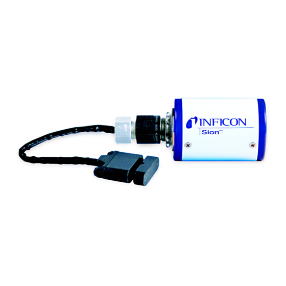
Introduction, Specifications, Installation and Operation 1.1 Introduction The INFICON® Sion™ RF detector is an ultra fast, ultra small, non intrusive RF detector capable of measuring both voltage and current signals from a Semiconductor Process tool. The Sion has been designed with tool connectivity... -
Page 14: Unpacking, Inspection, And Inventory Of Supplied Items
Sion Operating Manual 1.3 Unpacking, Inspection, and Inventory of Supplied Items Carefully remove all pieces the Sion from the shipping container. Some items may be in anti-static packaging and care should be taken during installation to not damage these sensitive components. -
Page 15: Safety
WARNING - Risk Of Electric Shock Do not open the instrument case! There are no user-serviceable components within the instrument case. Refer all maintenance to INFICON service or technically qualified personnel. WARNING Do not attempt to operate this instrument without proper training. -
Page 16: Specifications
Sion Operating Manual 1.5 Specifications 1.5.1 Detector Voltage Rating The Detector clamps to a tool RF delivery strap carrying up to 5000 V(dc) and up to 5000 V 1.5.2 Detector RF Input Range The Detector voltage input signal is 1 V to 5000 V strap voltage. -
Page 17: Nidaq Pci Board
Sion Operating Manual 1.5.8 NiDAQ PCI Board The computer interface board (NiDAQ PCI 6220M or 6224M) and the interface cable (NiDAQ 68 pin Cable) are purchased parts from National Instruments. Their specifications are included with the parts. 1.6 Physical Requirements 1.6.1 Detector Head Physical Dimensions... -
Page 18: Breakout Box Physical Dimensions
Operating and Storage humidity range ....10 to 90% RH non-condensing. 1.8.3.2 Sion Converter, Cables and Breakout Box Operating and Storage humidity range ....10 to 90% RH non-condensing. -
Page 19: Temperature Ranges
Storage temperature range ....-20 °C to 80 °C. 1.8.5.2 Sion Converter, Cables and Breakout Box Operating ambient temperature range ..10 °C to 50 °C. -
Page 20: Detector Assembly To Rf Strap Installation
Sion Operating Manual 1.10.2 Detector Assembly To RF Strap Installation WARNING - Risk Of Electric Shock Ensure all RF power has been disabled before any work is carried out on the tool. Remove the tool panel cover to expose the RF transmission strap or rod. -
Page 21: Converter Installation
Sion Operating Manual Figure 1-5 Sensor Distance From Ground Strap 1.10.3 Converter Installation WARNING Ensure all RF power has been disabled before any work is carried out on the tool. CAUTION The Converter may be installed on tool panel covers up to 4.11 mm (0.162 in.) thick. - Page 22 Sion Operating Manual Determine where on the tool panel cover the Converter is to be located. CAUTION The tool panel cover will need to be opened approximately 76 mm (3 in.) to access the Detector Assembly to Converter connection (see...
- Page 23 Sion Operating Manual Apply oil to the cutting edge of the punch, then slide the punch and thrust bearing over the bolt. Apply oil to the exposed bolt threads and then turn the nut onto the bolt. CAUTION Do not operate the hole punch dry. Make sure to lubricate the cutting edge of the punch and the bolt threads.
- Page 24 Sion Operating Manual From the outside of the tool panel cover, insert the Converter input connector into the D-shaped hole in the panel. (See Figure 1-7.) From the inside of the tool panel cover, secure the Converter to the panel: ...
-
Page 25: Detector Assembly To Converter Installation
Sion Operating Manual Figure 1-7 Converter Installation 1.10.4 Detector Assembly To Converter Installation WARNING Ensure all RF power has been disabled before any work is carried out on the tool. By hand, turn the knurled nut at the end of the Detector Assembly cable clockwise onto the Converter input connector until the knurled nut stops turning. - Page 26 Sion Operating Manual A gap between the knurled nut and the connector nut will be present on most installations (see Figure 1-8). The presence of a gap indicates a good electrical connection. If the knurled nut is in contact with the connector nut, the electrical...
-
Page 27: Nidaq Pci Board Installation
Sion Operating Manual 1.10.5 NiDAQ PCI Board Installation The following instructions pertain to a NiDAQ board installation in a computer having either the Windows XP or Windows Vista operating system. Open the FabGuard CD and locate the WinZip file named NIDAQmx 8.3.0 –... - Page 28 Sion Operating Manual After the installer initialization (see Figure 1-12) is completed, click Next at the Product Information screen (see Figure 1-13). Figure 1-12 Installer Initialization Progress Figure 1-13 Product Information 1 - 16...
- Page 29 Sion Operating Manual At the Destination Directory screen, click Next to install the software to the [C:\Program Files\National default destination directory of Instruments\]. (See Figure 1-14.) NOTE: A directory different than the default can be selected if required. Figure 1-14 Destination Directory Click Next at the Features screen.
- Page 30 Sion Operating Manual At the License Agreement screen, select I accept the License Agreement and click Next. (See Figure 1-16.) Figure 1-16 License Agreement Click Next at the Start Installation screen (see Figure 1-17). A screen showing software installation progress will appear (see Figure 1-18).
- Page 31 Sion Operating Manual Figure 1-18 Software Installation Progress Click Next at the Installation Complete screen. (See Figure 1-19.) Figure 1-19 Installation Complete Click Shut Down at the pop-up window. (See Figure 1-20.) Figure 1-20 Shut Down 1 - 19...
- Page 32 Sion Operating Manual With the computer powered down, install the NiDAQ PCI 6220M board (for use with a single Breakout Box) or NiDAQ PCI 6224M board (for use with two Breakout Boxes) into an unused PCI slot on the computer motherboard.
- Page 33 Sion Operating Manual Select Install from a list or specific location and click Next. (See Figure 1-22.) Figure 1-22 Found New Hardware Wizard - Install From List Select Don’t search, I will choose the driver to install and click Next. (See Figure 1-23.)
- Page 34 Sion Operating Manual Select the model of the installed DAQ board (PCI-6220 or PCI-6224) and click Next. (See Figure 1-24.) Figure 1-24 Found New Hardware Wizard - Select Board Model Click Finish to complete the installation of the driver software for the NiDAQ PCI board.
- Page 35 Sion Operating Manual Click Never Register at the NI Product Registration screen (see Figure 1-26). Click Yes when prompted Are you sure?. Figure 1-26 NI Product Registration Open the National Instruments Measurement & Automation Explorer by double-clicking the newly created icon on the Windows desktop.
- Page 36 Sion Operating Manual Right-click on NI PCI-6220 or NI PCI-6224, and click Self-Test (see Figure 1-28). Verify that the board passed the Self-Test, and click OK (see Figure 1-29). Figure 1-28 Measurement & Automation Explorer - Self Test Figure 1-29 Measurement & Automation Explorer - Self Test OK...
- Page 37 Sion Operating Manual Right-click on NI PCI-6220 or NI PCI-6224, and click Rename (see Figure 1-30). Rename the device Dev 16, and press Enter. Verify that the device is now named NI PCI-6220: Dev 16 or NI PCI-6224: Dev 16 (see Figure 1-31.)
-
Page 38: Cable Connections
Sion Operating Manual 1.10.6 Cable Connections Connect the Signal Cable to the Converter SENSOR I/O jack and a Breakout Box SENSORS jack as shown by Figure 1-32. Connect the NiDAQ 68 Pin Cable to the NiDAQ PCI 6220M or 6224M board and to the FABGUARD COMPUTER connector on the Breakout Box. -
Page 39: Converter Factory Settings
Particles generated during these arcs can reduce yields and significantly decrease profitability. The Sion is an ultra fast, ultra small RF detector, ideal for measuring micro arcs in chemical vapor deposition (CVD) and ETCH processes. The Sion collects voltage and current data at speeds up to 20 KHz, detecting even the smallest of arcs in the toughest of process conditions. -
Page 40: Endpoint Detection
The Sion provides an extremely sensitive, reliable and repeatable endpoint method for both etch processes and CVD chamber clean processes. Using RF technology, the Sion directly measures the chamber impedance that directly correlates to the chamber condition; which can eliminate frequent over-etch and under-etch processing conditions. -
Page 41: How The Sion Works
Sion Operating Manual Chapter 2 How The Sion Works 2.1 Theory of Operation The Detector samples the electric and magnetic fields surrounding the power transmission strap. A capacitive pickup generates a RF signal proportional to the magnitude of the voltage present on the strap, this is referred to as the Voltage Output. -
Page 42: Instrument Overview
Sion Operating Manual 2.2 Instrument Overview There are four modules that comprise the Sion system. Detector, see section 2.2.1. Converter, see section 2.2.2. Breakout box, see section 2.2.3. Data Acquisition Card, see section 2.2.4. 2.2.1 Detector The Detector houses the voltage and current pickups. -
Page 43: System Block Diagram
Sion Operating Manual 2.2.5 System Block Diagram Figure 2-1 System Block Diagram 2 - 3... - Page 44 Sion Operating Manual This page is intentionally blank. 2 - 4...
-
Page 45: Maintenance And Diagnosing Problems
Sion Operating Manual Chapter 3 Maintenance and Diagnosing Problems 3.1 Introduction All maintenance for this instrument should be referred to INFICON service or technically qualified personnel. Refer to How To Contact Customer Support. WARNING - Risk Of Electric Shock Do not open the instrument case! There are no user-serviceable components within the instrument case. -
Page 46: Symptom - Cause - Remedy Chart
3.3 Symptom - Cause - Remedy Chart Table 3-1 Symptom - Cause - Remedy Chart Symptom Cause Remedy 1. Incorrect level 1a. Converter factory 1a. Return Converter to INFICON settings have been for adjustment. (Refer to How To changed Contact Customer Support.) 1b. - Page 47 Sion Operating Manual Table 3-1 Symptom - Cause - Remedy Chart (continued) Symptom Cause Remedy 6. No signal 6a. Computer settings for 6a. Perform Measurement & NiDAQ PCI board are Automation Explorer Self-Test (refer incorrect section 1.10.5 on page 1-15, steps 18 - 20).
- Page 48 Sion Operating Manual This page is intentionally blank. 3 - 4...
-
Page 49: Spare Parts List
Sion Operating Manual Chapter 4 Spare Parts List 4.1 Sion Spare Parts List Sion Spare Parts List Part Number Description 035-0056 NiDAQ PCI 6220M Board (one cable connector) 035-0057 NiDAQ PCI 6224M Board (two cable connectors) 068-0451 Signal Cable 8 m (25 ft.) - Page 50 Sion Operating Manual This page is intentionally blank. 4 - 2...
-
Page 51: Index
Sion Operating Manual Index Breakout Box 1-4, 2-1, 2-2, 3-1, NiDAQ 68-pin Cable physical Dimensions NiDAQ PCI 6220M Board chamber cleaning Operation 1-27 computer interface cable interface card Plasma arcing 1-27 type plasma clean endpoint Converter 2-1, 2-2, plasma micro-arcing... - Page 52 Sion Operating Manual This page is intentionally blank. Index - 2...
Need help?
Do you have a question about the Sion and is the answer not in the manual?
Questions and answers