ASM 249159 Instructions-Repair/Parts

ASM 249159 Instructions-Repair/Parts

Airless sprayer, 120/240 vac

Advertisement

Instructions- -Repair/Parts
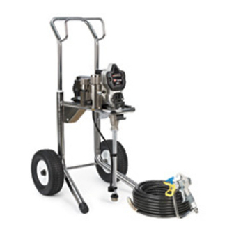
2300 and M2300 Airless Sprayer
- For portable spray application of architectural paints and coatings -
Important Safety Instructions
Read all warnings and instructions in this manual.
Save these instructions.
Model 249159 and 249168: 120 Vac
Model 246803 and 249169: 240 Vac
3000 psi (207 bar, 20.7 MPa ) Maximum Working Pressure
Related manuals
. . . . . . .
309878
. . . . . . .
309971
. . . . . . .
309053
Model 246803
(Series A, B)
. . . . . . .
311062
Models 249159,
249168, 249169,
246803 (Series C)
Model 249168,
249169, 246803
Model 249159
309879L
ti6748a

Advertisement

Table of Contents
loading
Need help?

Need help?

Do you have a question about the 249159 and is the answer not in the manual?

Questions and answers

Summary of Contents for ASM 249159

  • Page 1 - For portable spray application of architectural paints and coatings - Important Safety Instructions Read all warnings and instructions in this manual. Save these instructions. Model 249159 and 249168: 120 Vac Model 246803 and 249169: 240 Vac 3000 psi (207 bar, 20.7 MPa ) Maximum Working Pressure Related manuals .
  • Page 2: Specifications

    Specifications This equipment is not intended for use with flammable or combustible materials used in places such as cabinet shops or other “factory” or fixed locations. If you intend to use this equipment in this type of application, you must comply with NFPA 33 and OSHA requirements for the use of flammable and combustible materials.
  • Page 3: Fire And Explosion Hazard

    Warnings The following are general warnings related to the setup, use, grounding, maintenance and repair of this equipment. Additional, more specific warnings may be found throughout the body of this manual where applicable. Symbols appearing in the body of the manual refer to these general warnings. When these symbols appear through the manual, refer back to these pages for a description of the specific hazard.
  • Page 4 Read fluid and solvent manufacturer’s warnings. For complete information about your material, request MSDS from distributor or retailer. D Check equipment daily. Repair or replace worn or damaged parts immediately with genuine ASM replacement parts only. D Do not alter or modify equipment.
  • Page 5: Component Identification And Function

    Component Identification and Function ti6749a Fig. 1 Motor DC motor, permanent magnet, totally enclosed, fan cooled Drive Assembly Transfers power from DC motor to displacement pump Displacement Pump Transfers fluid to be sprayed from source through spray gun Fluid Outlet Spray gun is connected here Prime Valve Used to prime and drain sprayer (also relieves fluid outlet pressure) when...
  • Page 6: General Repair Information

    General Repair Information Pressure Relief Procedure 1. Keep all screws, nuts, washers, gaskets, and electrical fittings removed during repair proce- dures. These parts are not normally provided with replacement assemblies. System pressure must be manually relieved to prevent system from starting or spraying accidentally. Fluid under high pressure can be injected through skin and To reduce risk of serious injury, including electric shock, cause serious injury.
  • Page 7: Troubleshooting

    Grounding Grounding Plug The sprayer must be grounded. Grounding reduces Grounded the risk of static and electric shock by providing an Outlets escape wire for the electrical current due to static build up or in the event of a short circuit. 1.
  • Page 8 Troubleshooting MOTOR WON’T OPERATE (Continued) TYPE OF PROBLEM WHAT TO CHECK WHAT TO DO If check is OK, go to next check When check is not OK refer to this column Basic Electrical Problems 1. That motor leads are securely fastened and 1.
  • Page 9: Low Or Fluctuating Output

    Troubleshooting LOW OR FLUCTUATING OUTPUT TYPE OF PROBLEM WHAT TO CHECK WHAT TO DO If check is OK, go to next check When check is not OK refer to this column Low Output 1. For worn spray tip. 1. Follow Pressure Relief Procedure Warn- ing, then replace tip.
  • Page 10 Troubleshooting LOW OR FLUCTUATING OUTPUT TYPE OF PROBLEM WHAT TO CHECK WHAT TO DO If check is OK, go to next check When check is not OK refer to this column Motor runs and pump strokes 1. Paint supply. 1. Refill and reprime pump. 2.
  • Page 11: Electrical Short

    Troubleshooting MOTOR IS HOT AND RUNS INTERMITTENTLY TYPE OF PROBLEM WHAT TO CHECK WHAT TO DO If check is OK, go to next check When check is not OK refer to this column Motor is hot and runs intermit- 1. Determine if sprayer was operated at high 1.
  • Page 12: Motor Brush Replacement

    Spin Test Setup Armature, Brushes, and Motor Wiring Open Circuit Test (Continuity) 1. Connect red and black motor leads together with test lead. Turn motor fan by hand at about two Electric Shock Hazard; page 6. revolutions per second. 2. If uneven or no resistance, check for: broken brush To check armature, motor winding and brush electrical springs, brush leads, motor leads;...
  • Page 13: Motor Brush Installation

    Motor Brush Replacement 4. Fig. 5. Push in spring clip (A) to release hook (B) from brush holder (C). Pull out spring clip (A). 5. Fig. 5. Pull brush lead (D) out of terminal (E). Remove brush (F). Motor lead; do not disconnect Minimum 0.5”...
  • Page 14: On/Off Switch Replacement

    On/Off Switch Replacement 120 Vac (249168) Removal Installation 1. Install new ON/OFF switch (23). Install locking ring (24) and toggle boot (25). 2. Connect four wires (A) to ON/OFF switch (23). 1. Relieve pressure; page 6. 2. Fig. 7. Remove four screws (18) and pressure 3.
  • Page 15: Wiring Diagram

    Wiring Diagram 120 Vac (249168) Caution Filter Board Heat from inductor coil of filter board may destroy wire insulation that comes in contact with it. Exposed wires could cause shorts and component damage. Bundle and tie all loose Brown wires so none lay in contact with inductor coil of filter board.
  • Page 16 On/Off Switch Replacement 240 Vac (249169) Removal Installation 1. Install new ON/OFF switch (23). Install locking ring (24) and toggle boot (25). 2. Connect four wires (A) to ON/OFF switch. 1. Relieve pressure; page 6. 2. Fig. 9. Remove pressure control cover (39). 3.
  • Page 17 Wiring Diagram 240 Vac (249169) Caution Heat from inductor coil of filter board may destroy wire insulation that comes in contact Filter Board with it. Exposed wires could cause shorts and Blue component damage. Bundle and tie all loose wires so none lay in contact with inductor coil Brown of filter board.
  • Page 18 On/Off Switch Replacement 240 Vac (246803) Removal Installation 1. Install new ON/OFF switch (23). Install locking ring (24) and toggle boot (25). 2. Connect four wires (A) to ON/OFF switch. 1. Relieve pressure; page 6. 3. Install display connector (B) in plug (C). 2.
  • Page 19 Wiring Diagram 240 Vac (246803) Caution Brown Blue Heat from inductor coil of filter board may Ref 23 destroy wire insulation that comes in contact with it. Exposed wires could cause shorts and component damage. Bundle and tie all loose wires so none lay in contact with inductor coil of filter board.
  • Page 20 On/Off Switch Replacement 120 Vac (249159) Removal Installation 1. Install new ON/OFF switch (23). Install locking ring (24) and toggle boot (25). 2. Connect two wires (A) to ON/OFF switch. 1. Relieve pressure; page 6. 3. Install pressure control cover (39) with four screws 2.
  • Page 21: Pressure Control Repair

    Pressure Control Repair Motor Control Board Removal Installation 1. Clean pad on rear of motor control board. Apply small amount of thermal compound 073019 to pad. 1. Relieve pressure; page 6. 2. Install motor control board (35) with five screws (36).
  • Page 22: Pressure Control Transducer Removal

    Pressure Control Repair Pressure Control Transducer Pressure Adjust Potentiometer Removal Removal 1. Relieve pressure; page 6. 1. Relieve pressure; page 6. 2. Fig. 7. Remove four screws (18) and cover (39). 2. Fig. 7. Remove four screws (18) and cover (39). 3.
  • Page 23: Drive Housing Replacement

    Drive Housing Replacement 5. Remove two back screws (22). CAUTION 6. Pull drive housing (10) off of motor (1). Do not drop gear cluster (7) when removing drive housing (10). Gear cluster may stay engaged in Assembly motor front end bell or drive housing. 1.
  • Page 24: Motor Replacement

    Motor Replacement Disassembly 6. Remove strain relief (37, page 34, 38). 7. Remove three screws (22) behind board and remove control housing (21). 8. Remove four screws (22) and motor (1) from 1. Relieve pressure; page 6. frame (63). 2. Remove pump (13); Displacement Pump Re- Assembly placement, page 25.
  • Page 25: Displacement Pump Replacement

    Displacement Pump Replacement See parts on page 26 for sprayer part number references. Removal 1. Flush pump (13). 4. Cycle pump until pump pin (9a) is in position to be removed. Remove pump pin (9a). 5. Fig. 17. Remove suction tube (78) and hose (19). 2.
  • Page 26: Parts Drawing

    Parts Drawing Model 246803, Series A Detail A Detail A Ref 19 Ref 79 ti6754a 309879...
  • Page 27: Parts List - Sprayer

    Parts List - Sprayer Model 246803, Series A NO. PART NO. DESCRIPTION NO. PART NO. DESCRIPTION 242015* MOTOR, 240 Vac 110243 RING, retaining 115525 BLADE, fan motor 192027 SLEEVE, cart 243219 GEAR, combination 111590 BUTTON, snap 243218 CRANK SHAFT 183350 WASHER 243221 CONNECTING ROD...
  • Page 28 Parts Drawing Model 246803, Series B and C Series C shown Detail A Detail A Ref 19 ti6755a Ref 79 309879...
  • Page 29 Parts List - Sprayer Model 246803, Series B and C NO. PART NO. DESCRIPTION NO. PART NO. DESCRIPTION 242015* MOTOR, 240 Vac 183350 WASHER 243219 GEAR, combination 287159 SHROUD, motor 243218 CRANK SHAFT includes 74a, 74b, 74c, 126 and 127 243221 CONNECTING ROD 195159...
  • Page 30 Parts Drawing Model 246803, Series A, B, and C Ref 1 ti6054b Ref 45 26 Ref 52 Ref Parts List - - Sprayer NO. PART NO. DESCRIPTION NO. PART NO. DESCRIPTION 115492 SCREW, slot hd, hex, washer hd 243539 CONDUCTOR, ground 276539 HOUSING, control 241946...
  • Page 31 Notes 309879...
  • Page 32 Parts Drawing Model 249168 and 246169 Detail A Detail A Ref 19 ti6679a 309879...
  • Page 33 Parts List - Sprayer Model 249168 and 249169 NO. PART NO. DESCRIPTION NO. PART NO. DESCRIPTION 242012* MOTOR, 120 Vac 183350 WASHER 242015* MOTOR, 240 Vac 287159 SHROUD, motor 243219 GEAR, combination includes 74a, 74b, 74c, 126 and 127 243218 CRANK SHAFT 195159 BRACKET, shroud...
  • Page 34 Parts Drawing Model 249168 and 249169 Ref 1 ti6418A Ref 45 26 Ref 52 Ref Parts List - - Sprayer NO. PART NO. DESCRIPTION NO. PART NO. DESCRIPTION 115492 SCREW, slot hd, hex, washer hd 241992 SCREW, 6--32 X 1/2, TAPTITE 195528 HOUSING, control, 120Vac 115756...
  • Page 35 Notes 309879...
  • Page 36 Parts Drawing Model 249159, Series A Detail A Detail A Ref 19 Ref 79 ti6035b 309879...
  • Page 37 Parts List - Sprayer Model 249159 Series A NO. PART NO. DESCRIPTION NO. PART NO. DESCRIPTION 242012* MOTOR, 120 Vac 15C391 SHROUD, motor 243219 GEAR, combination includes 74a, 74b, 74c, 126 and 127 243218 CRANK SHAFT 195159 BRACKET, shroud 243221...
  • Page 38 Parts Drawing Model 249159 Ref 1 ti6036a Ref 45 Parts List - - Sprayer NO. PART NO. DESCRIPTION NO. PART NO. DESCRIPTION 115492 SCREW, slot hd, hex, washer hd 15A356 LABEL, control 276539 HOUSING, control 112382 NUT, shaft, sealing 115495...
  • Page 39: Technical Data

    Technical Data 100--110V 220--240V Generator Motor HP Cycles per gal- Maximum Maximum Fluid Outlet ∅, A, Hz ∅, A, Hz Minimum W lon (liter) Delivery gpm Tip size npsm (lpm) 1, 15, 50/60 1, 10, 50/60 3750 3/4 (560) 680 (180) 0.54 (2.09) 0.023 1/4 in...
  • Page 40: Asm Standard Warranty

    ASM distributor to the original purchaser for use. With the exception of any special, extended, or limited warranty published by ASM, ASM will, for a period of twelve months from the date of sale, repair or replace any part of the equipment determined by ASM to be defective.

This manual is also suitable for:

2491682300M2300249169246803

Table of Contents