
Related Manuals for Nibe SPLIT HBS 12


Summary of Contents for Nibe SPLIT HBS 12
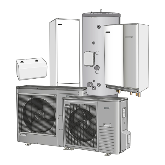
- Page 1 MOS GB 1337-3 INSTALLATION AND MAINTENANCE INSTRUCTIONS NIBE™ SPLIT NIBE™ SPLIT 431119 AMS 10-8/AMS 10-12, HBS 12, HE 30/HEV 300/HEV 500...
- Page 2 HE 30 HEV 300 HEV 500 HBS 12...
- Page 3 AMS 10-8 AMS 10-12...
-
Page 5: Table Of Contents
Pump capacity diagram Product information Connecting HBS 12 to tank Features of NIBE SPLIT Connecting the climate system Principle of operation NIBE SPLIT Connecting the hot water heater Connection of external heat source Front panel, indoor module Waste exchanger part... -
Page 6: N] Supply Temp
AMS 10 alarm Sound pressure levels Hot water alarm Accessories Supply alarm Outdoor sensor alarm Electrical circuit diagram Safety precautions HBS 12 Caution AMS 10-8 Care AMS 10-12 Especially for units intended for R410A Item register Component positions NIBE™ SPLIT... -
Page 7: Installation Data
(HE 30, HEV 300, HEV 500), which takes care of the regulation and heat distribution in the house. In order to gain the greatest benefit from the NIBE SPLIT system, please refer to the 'For Home Owners' chapter within this Installation and Maintenance Manual. -
Page 8: For Home Owners
Product information Function NIBE SPLIT is a complete modern heat pump system that NIBE SPLIT is a system that can produce heating, hot water offers effective energy saving and reduced carbon dioxide and cooling. emissions. NIBE SPLIT gives safe and economical climate The principle during heating can be simplified as follows: control. -
Page 9: Front Panel, Indoor Module
For Home Owners Front panel, indoor module Front panel, indoor module I II III I II 5 0 . 0 ° C 13.43 NIBE™ SPLIT... -
Page 10: How To Use The Front Panel
A key lock can be activated in the main menus by simultan- eously pressing the plus and the minus buttons. The key symbol will then be shown on the display. The same procedure is used to deactivate the key lock. NIBE™ SPLIT... -
Page 11: Comfort Setting Heating General
This means that the operating mode switches between "Heating" and "Hot water". Current oper- ating mode is shown within brackets. The circulation pump is permitted to operate when there is a need. 2. ”AutoK”* NIBE™ SPLIT... -
Page 12: Default Setting
- 40 OUTSIDE TEMPERATURE FÖRSKJUTNING UTETEMPERATUR VÄRMEKURVA (0) OFFSET HEAT CURVE SUPPLY TEMPERATURE HEATING CURVE VÄRMEKURVA 15 14 13 12 11 - 10 - 20 - 30 - 40 OUTSIDE TEMPERATURE FÖRSKJUTNING UTETEMPERATUR VÄRMEKURVA (+2) OFFSET HEAT CURVE NIBE™ SPLIT... -
Page 13: Readjusting The Default Settings
2.1.2 by one incre- ment. Warm weather conditions If the room temperature is low, increase the “Heating curve offset” setting by one step clockwise. If the room temperature is high, reduce the “Heating curve offset” setting by one step anti-clockwise. NIBE™ SPLIT... -
Page 14: Comfort Setting Cooling General
If RG 10 is present, the condition for cooling is that the room temperature has exceeded the set room temperature (menu 6.3) by the set value in menu 8.2.5 and that the outdoor temperature is equivalent to or exceeds the set outdoor temperature value (menu 8.2.4). NIBE™ SPLIT... -
Page 15: Comfort Setting Hot Water
When: ”A” appears above the icon, temporary extra hot water is active. ”B” appears above the icon, time based extra hot water is active. NIBE™ SPLIT... - Page 16 (A) when the button is pressed and when you continue to press the button the mode changes between 3 hours and standby mode. The increased temperature is maintained by the electrical addition until the period of time has ex- pired. NIBE™ SPLIT...
-
Page 17: Maintenance
HBS 12 and AMS 10 require minimal maintenance after HEV 300/HEV 500 commissioning. NIBE SPLIT contains many components and is why monit- oring functions are integrated to help you. If something abnormal occurs, a message appears about malfunctions in the form of different ”alarm” texts in dis- play. -
Page 18: Emptying The Coil In The Water Heater
WARNING! Rotating fan in AMS 10. Saving tips Your NIBE SPLIT installation produces heat and hot water according to your needs. It also attempts to carry out all requirements with all available ”aids” from the control settings made. The indoor temperature is naturally affected by the energy consumption. -
Page 19: Dealing With Comfort Disruption
Activate operating mode ”Only additional heat”. Display not lit. Check and replace any blown circuit and main fuses. Check that the circuit breaker to the indoor unit is not off. Check that the switch (SF1) is in normal position (1). NIBE™ SPLIT... -
Page 20: Operating Mode "Add. Heat Only
300, HEV 500 are active. An electrical step of 4 kW is connected. The immersion heater is controlled by a separate thermostat (BT30). The automatic heating control system is not operational, so manual shunt operation is required. Call installer. NIBE™ SPLIT... -
Page 21: Alarm Indications
For Home Owners Alarm indications Alarm indications There are many monitoring functions integrated in NIBE Different types of alarms SPLIT to alert you to any malfunctions, the control com- Alarms with automatic reset (do not need to be acknow- puter transmits alarm signals that can be read from the ledged when the cause has disappeared). -
Page 22: For The Installer
HE 30 must be transported and stored horizontally on its back in a dry place. Supplied components HBS 12 Outside sensor Straps for 1 phase connection Current sensor, 3 phase Keys for the actuator motors Particle filter and shut-off valve NIBE™ SPLIT... -
Page 23: Assembly
220 mm above the water heater for any future service. Dimensioning expansion vessel Internal volume in ? for calculating expansion vessel is 500 l. The expansion vessel's volume must be at least 5 % of the total volume. Volume per component HBS 12 NIBE™ SPLIT... -
Page 24: Manual Shunting
HBS 12, the water heater and AMS 10-8/AMS 10-12. See page 34. 4. Connect supply to HBS 12. See page 32. 5. Follow the commissioning instructions on page 39. NIBE™ SPLIT... -
Page 25: Pipe Installation General
For correct function the volume of the climate system must meet the installation requirements, see page 27. If this is XL19 not fulfilled a volume vessel needs to be installed. (NIBE UKV). XL18 For more options, see the docking description on page 27. -
Page 26: Pump Capacity Diagram
30. Respective maximum flows must not be exceeded. Connecting HBS 12 to tank It is necessary to connect a water heater or a tank to HBS 12. Pipe connections for the climate system are made at the bottom of HBS 12. NIBE™ SPLIT... -
Page 27: Connecting The Climate System
Connect HBS 12 pipe connections (XL1) and (XL2) to the climate system. Backventil NOTE Blandningsventil The term "Climate system" which is used in these in- stallation and maintenance instructions regards heating or cooling systems from HBS 12 for heating or cooling. NIBE™ SPLIT... -
Page 28: Connection Of External Heat Source
AMS 10 and HBS 12. Installation must be carried out in accordance with current norms and directives. AMS 10-8/AMS 10-12 limitations Maximum pipe length, AMS 10-8 and AMS 10-12 (L): 30m. Maximum height difference (H): ±7 m. HEV 500 NIBE™ SPLIT... - Page 29 Connect the flare connector and tighten to the following torque. Use the "Tightening angle" if a torque wrench is not available. Outer diamet- Tightening Tightening Recommen- er, copper torque (Nm) angle (°) ded tool pipe (mm) length (mm) Ø9.52 34~42 30~45 Ø15.88 68~82 15~20 NIBE™ SPLIT...
- Page 30 When carrying out pipe connections, pressure tests, leak tests and vacuuming, the service valves (QM35, QM36) can be opened, to fill the pipes and HBS 12 with refriger- ant. NIBE™ SPLIT...
-
Page 31: Dockings
For the Installer Pipe installation Dockings General NIBE SPLIT can be connected in several different ways, some of which are shown on the following pages. For more detailed docking descriptions, see www.nibe.eu. Installation requirements AMS 10-8 AMS 10-12 Max pressure, climate system 0.25 MPa (2.5 Bar) - Page 32 For the Installer Pipe installation NIBE SPLIT with climate system and any addition Klimatsystem Överströmnings- ventil RG10/ RE10 Erf. säker- hetsutr. HBS 10-12 BT 1 Extern tillsats HEV 300/HEV 500 AMS 10-8/AMS 10-12 NIBE™ SPLIT...
- Page 33 For the Installer Pipe installation Klimatsystem Överströmnings- ventil RG10/ RE10 HBS 10-12 BT 1 HE 30 AMS 10-8/AMS 10-12 NOTE These are outline diagrams. Actual installations must be planned according to applicable standards. NIBE™ SPLIT...
- Page 34 Climate system 2 EP22 Climate system 3 Buffer vessel UKV Temperature sensor, flow pipe QN12 Reversing valve, cooling/heating GP12 Charge pump Temperature sensor, return Miscellaneous Non-return valve GP20 Circulation pump Temperature sensor, outdoor QN25 Shunt valve Expansion vessel NIBE™ SPLIT...
- Page 35 ALT 1 GAS V. GP12 GP12 Explanation Expansion vessel Oil/Pellet boiler GP32 Pump station, limits low temperature Accumulator tank Safety valve Particle filter Immersion heater GP12 Charge pump Non-return valve Wood-fired boiler GP31 Pump station, limits high temperat- NIBE™ SPLIT...
-
Page 36: Electrical Installation General
The switch (SF1) must not be moved to “1” or “ ” until the boiler has been filled with water. The circu- lation pump and immersion heater may become damaged. Principle diagram, electrical installation HE 30 * Only in a 3-phase installation. NIBE™ SPLIT... - Page 37 Terminal block, external immer- sion heater and temperature HEV 500 limiter/thermostat emergency mode FD1-BT30. X100 Terminal block X101 Terminal block Switch Miniature circuit breaker, con- trol system Miniature circuit breaker, out- door unit Miniature circuit breaker, ex- ternal immersion heater NIBE™ SPLIT...
-
Page 38: Connecting The Supply
90 and 100°C and can be manually reset. Resetting The temperature limiter/emergency mode thermostat (FD1-BT30) is located in the tanks' electrical connections. The temperature limiter is reset by firmly pressing in its button. NOTE Reset the temperature limiter, it may have tripped during transport. NIBE™ SPLIT... -
Page 39: Connection Between Hbs 12 And He 30, Hev 300, Hev 500
(black and grey) as well as earth (yellow/green) as illus- trated: (AMS 10-12:-X1) (ACVM 10- Connection between HBS 12 and HE 30, HEV 300, HEV 500 HBS 10-12/HBS 10-16 HE 10-30/HEV 10-300/HEV 10-500 5G1.5 mm Temperaturebegränsare -FD1-BT30 Elpatron -EB2 3x2000W Elpatron -EB2 3x1000W -X100 NIBE™ SPLIT... -
Page 40: Setting Max Power, Electrical Addition
Connect the current sensors to a multi-core cable in an enclosure next to the distribution box. Use unscreened multi-core cable of at least 0.50 mm , from the enclosure to HBS 12. In HBS 12 connect the cable to the current limiter board (AA22) on terminal X1:8–11. NIBE™ SPLIT... -
Page 41: Connection Of Centralised Load Control/Tariff
-10 and +10. The value for the change Ext. 1 step is set in menu 2.4, "External adjustment". 1. Remove the strap on terminal block X3:2 and X3:3. See section Component positions on page 78 and section Electrical circuit diagram on page 69. NIBE™ SPLIT... - Page 42 2. Connect the addition's phase to terminal block X3:2 (230 V) and X3:4 (N) (max 0.2 A). 3. Use the accessory HR10 when the need for potential for signal and/or when controlling external charge pumps. 4. Set ”Ext. 1 step" in menu 9.2.8. NIBE™ SPLIT...
-
Page 43: Start-Up And Inspection Preparations
7. Select “Service” in menu 8.1.1. 8. Select addition type in menu 9.2.8. 9. Set the fuse size on knob (R24). Check the value in menu 8.3.1. 10. Set the max immersion heater output on knob (R25). Check the value in menu 8.3.2. NIBE™ SPLIT... -
Page 44: Setting System Flow Heating
4. Select operating mode "Add. heat only" by holding in the operating mode button for 7 seconds. 5. Set the date and time in menu 7.1 and 7.2. 6. Select “Service” in menu 8.1.1. 7. Select addition type in menu 9.2.8. NIBE™ SPLIT... -
Page 45: Secondary Adjustment
(FL2). The latter must be operated carefully as it opens quickly. When the system is stable (correct pressure and all air eliminated) the automatic heating control system can be set as required. See Default setting on page 8. NIBE™ SPLIT... -
Page 46: Checklist: Checks Before Commissioning
End pressure vacuum Electrical installation Notes Checked Property's main fuse Group fuse Current limiter/current sensor KVR 10* Accessories Notes Checked External circulation pump Overflow valve Room sensor Drain pan heater Solar control KVR 10* *Requires software version 1.05 or later. NIBE™ SPLIT... -
Page 47: Control Display
The Enter button is used to select submenus of the current menu, to permit parameters to be changed and to confirm any changes to paramet- ers. When the menu number ends with a zero this indicates that there is a submenu. NIBE™ SPLIT... -
Page 48: Menu Tree
1.10.4 [S] HW reg min 1.10.10 [S] Return 1.11.0 [S] CompFreq HW set- tings 1.11.1 [S] CompFreq HW set 1.11.2 [S] CompFreq manual 1.11.3 [S] CompFreq at +20 1.11.4 [S] CompFreq at -5 1.11.5 [S] Return 1.12 [N] Return NIBE™ SPLIT... - Page 49 2.2.3.2 [U] Supply temp.at +40 2.2.3.3 [U] Return 2.2.4 [U] Min supply cooling 2.2.5 [U] Circ-pump speed cool 2.2.6 [N] Return 2.3 [U] Max supply temp. 2.4 [U] External adjustment 2.5 [U] Supply/Return temp. 2.6 [U] Degree minutes 2.7 [N] Return NIBE™ SPLIT...
- Page 50 3.5 [U] External adjust. 2 3.6.0 [U] Own heating curve 2 3.6.1 [U] Supply temp.at +20 3.6.2 [U] Supply temp.at -20 3.6.3 [U] Buckling temperature 3.6.4 [U] Supply t. at buckl 3.6.5 [U] Return 3.7 [U] Supply/Return temp 2 3.8 [N] Return NIBE™ SPLIT...
- Page 51 5.14.0 [U] CompFreq act/set 5.14.1 [U] OU current CT 5.14.2 [U] Inverter temp Tho- 5.14.3 [U] Return 5.15.0 [S] OU communication 5.15.1 [S] Com. error rate 5.15.2 [S] Com. errors 5.15.3 [S] Reset com. errors 5.15.4 [S] Return 5.16 [N] Return NIBE™ SPLIT...
- Page 52 8.5.0 [U] Period settings 8.5.1 [U] Period time 7.5.6 [U] Return 8.5.2 [U] Max time for HW 7.6.0 [N] Silent mode 7.6.1 [N] Silent mode time 8.5.3 [U] Return 7.6.2 [N] Return 8.6 [N] Return 7.7 [N] Return NIBE™ SPLIT...
- Page 53 9.3.7.14 [S] K13 9.3.7.15 [S] K14 9.3.7.16 [S] Alarm 1 9.3.7.17 [S] Alarm 2 9.3.7.18 [S] Return 9.3.8 [S] Factory setting 9.3.9 [S] Operating state 9.3.10.0 [S] Floor drying setting 9.3.10.1 [S] Floor drying 9.3.10.2 [S] Period time 1 NIBE™ SPLIT...
- Page 54 9.8.1.0 [S] Log 1 9.8.x.1 [S] Time 9.8.x.2 [S] Alarm type 9.8.x.3 [S] Run status 9.8.x.4 [S] Run status last 9.8.x.5 [S] Run status time 9.8.x.6 [S] Run time compressor 9.8.x.7 [S] Outdoor avg. 1min. 9.8.x.8 [S] Outdoor temp Tho-A NIBE™ SPLIT...
- Page 55 9.8.x.24 [S] Relay status 9-14 9.8.x.25 [S] Program status 1-8 9.8.x.26 [S] Program status 9-16 9.8.x.27 [S] Return 9.8.2.0 [S] Log 2 9.8.3.0 [S] Log 3 9.8.4.0 [S] Log 4 9.8.5 [S] Clear alarm log 9.8.6 [S] Return 9.9 [S] Return NIBE™ SPLIT...
-
Page 56: Main Menus
Different temperature reductions and increases at selected times are also set from this menu. Menu 8.0 [N] Other adjustments Settings regarding the menu type, language, operating mode settings and load monitor reading are made in the sub-menus to this menu. NIBE™ SPLIT... -
Page 57: 1.0 [N] Hot Water Temp
The set point value for temperatures above the stop value for hot water charging is selected within brackets. 2.0 [N] Supply temp. Setting range: 0 – 10 °C Menu 2.1.0 [N] Heating settings Default value: 2.0 °C Heating settings are made in the sub-menus for this menu. NIBE™ SPLIT... - Page 58 Setting range: 0 – 25* °C Menu 2.1.3.5 [U] Return Default value: 10 °C Return to menu 2.1.3.0. Menu 2.2.3.3 [U] Return Return to menu 2.2.3.0. * Limited by menu 2.3 Max supply temp.. * Limited by menu 2.3 Max supply temp.. NIBE™ SPLIT...
- Page 59 Setting range: -32000 – 32000 Menu 2.7 [N] Return Return to menu 2.0. * Limited by menu 3.4 Max supply temp. 2. NIBE™ SPLIT...
-
Page 60: 4.0 [N] Outdoor Temp
Menu 5.2 [N] Run time compressor Menu 5.15.2 [S] Com. errors The accumulated time that the compressor has been used Shows the total number of incorrect communications with in AMS 10 is shown here. AMS 10 since start-up. NIBE™ SPLIT... -
Page 61: 6.0 [N] Room Temperature
23:59 on the selected date. The time for the day change, e.g. night reduction is chosen Same date in menu 7.5.1 and 7.5.2 deactivates the holiday here. function. *Requires accessory and activation in menu 9.3.6. NIBE™ SPLIT... -
Page 62: 8.0 [N] Other Adjustments
The average outdoor air temperature at which the heat pump (in auto mode) is to stop heat production. When the average outdoor air temperature falls below Stop temp. heating – Hysteresis (menu 8.2.5) heating starts again. Setting range: 1 – 43 °C Default value: 17 °C NIBE™ SPLIT... -
Page 63: 9.0 [S] Service Menus
Menu 8.5.1 [U] Period time set value. The length of time for production of hot water and heating Setting range: 10 – 43 °C is set here. Default value: 10 °C Setting range: 5 – 60 min Default value: 60 min NIBE™ SPLIT... - Page 64 HW. If HW is colder, the electrical addition starts. Setting range: 20 – 30 °C Select “On” here if logger is installed. Default value: 20 °C Setting range: Off, On Menu 9.1.13 [S] Return Default value: Off Return to menu 9.1.0. NIBE™ SPLIT...
- Page 65 2 minutes, 12 hours after last operation. Here you can select to restore factory settings in HBS 12. Setting range: Off, On When returning to the factory settings the language Default value: On switches to English. Setting range: Yes, No Default value: No NIBE™ SPLIT...
- Page 66 Menu 9.5.13 [S] Period Menu 9.3.17 [S] Freeze protection HX Period counter for switching between hot water and heating/cooling. Select here whether heat exchanger anti freeze is to be active or not. Setting range: On, Off Default value: On NIBE™ SPLIT...
- Page 67 Select here the time that the compressor is to run at fixed frequency after shifting to heating. The compressor then runs at min frequency or at the frequency it had before hot water charging. Setting range: 3 – 60 min Default value: 3 min NIBE™ SPLIT...
- Page 68 Inverter error Menu 9.8.6 [S] Return Inverter error Return to menu 9.8.0. Inverter error Inverter error Menu 9.9 [S] Return Fan alarm Return to menu 9.0. LP alarm Inverter error Sensor fault OU LP alarm Low refrigerant Inverter error NIBE™ SPLIT...
-
Page 69: Alarm List Acknowledging Alarms
- Blown circuit fuse (L3) - Tripped miniature circuit breaker (-FA2) Low condenser out Too low temperature out from the condenser. - Low temperature during cooling Occurs if alarm 70 occurs 3 times within an hour. - Low flow during cooling NIBE™ SPLIT... -
Page 70: Ams 10 Alarm
- Defective control board in AMS 10 S. fault Tho-R Sensor fault, heat exchanger in AMS 10 (Tho-R). - Open-circuit or short-circuit on sensor input - Sensor does not work (see "Temperature sensor" section) - Defective control board in AMS 10 NIBE™ SPLIT... - Page 71 - Open circuit or short circuit on input for suction gas sensor (Tho-S) - Defective suction gas sensor (Tho-S) Inverter error Continuous deviation on power transistor for 15 - Defective fan motor minutes. - Defective circuit board for inverter in AMS 10 NIBE™ SPLIT...
-
Page 72: Hot Water Alarm
- Open-circuit or short-circuit on sensor input - Sensor does not work (see "Temperature sensor" section) Sensor fault VBF2 Sensor fault, supply, system 2. - Open-circuit or short-circuit on sensor input - Sensor does not work (see "Temperature sensor" section) NIBE™ SPLIT... -
Page 73: Outdoor Sensor Alarm
The following alarms set so that the system runs at minimum permitted supply temperature. Alarm Alarm text on the dis- Description May be due to play Sensor fault UG Sensor fault, outdoor temperature (BT1). - Open-circuit or short-circuit on sensor input - Sensor does not work (see "Temperature sensor" section) NIBE™ SPLIT... -
Page 74: Electrical Circuit Diagram
Miscellaneous Electrical circuit diagram Electrical circuit diagram HBS 12 NIBE™ SPLIT... - Page 75 Miscellaneous Electrical circuit diagram NIBE™ SPLIT...
- Page 76 Miscellaneous Electrical circuit diagram NIBE™ SPLIT...
- Page 77 Miscellaneous Electrical circuit diagram NIBE™ SPLIT...
- Page 78 Miscellaneous Electrical circuit diagram NIBE™ SPLIT...
- Page 79 Miscellaneous Electrical circuit diagram NIBE™ SPLIT...
-
Page 80: Ams
− unit only 3 〜 + CNA1 A/F MODULE (WH) CNN1 CNTH CNIP CNPS (BR) (RD) (RD) (RD) (WH) (BK) (WH) t° t° t° t° t° t° 63H1 Tho-R1 Tho-D Tho-S Tho-A Tho-P Tho-R2 Two fan unit only NIBE™ SPLIT... - Page 81 SW3, 5, 7, 8 Local settings Terminal block Tho-A Temperature sensor, outdoor air Tho-D Temperature sensor, hot gas Tho-IPM Temperature sensor, IPM Tho-R1 Temperature sensor, heat exchanger out Tho-R2 Temperature sensor, heat exchanger, in Tho-S Temperature sensor, suction gas NIBE™ SPLIT...
-
Page 82: Component Positions
Miscellaneous Component positions Component positions HBS 12 Component image BT12 AA23 AA22-X1 FD1-QA41 AA22-R26 AA22-R25 AA22-R24 AA22 AA21 AA22-X4 BT15 QN11 QM40 QM31 QM30 XL14 QM20 XL13 XL18 XL19 NIBE™ SPLIT... - Page 83 CPU card AA22 EBV card R24 Setting, fuse size R25 Setting, max power, electrical addition R26 Setting, max boiler temperature X1 Terminal block X4 Terminal block AA23 Communication board Contactor Contactor Contactor Component location according to IEC 62400. NIBE™ SPLIT...
-
Page 84: He 30, Hev 300, Hev 500
Miscellaneous Component positions HE 30, HEV 300, HEV 500 Component image QM20 BT19 XL18 FD1-BT30 X100 BT19 X101 X101 X100 BT24 BT24 XL19 HEV 500 XL18 X101 XL19 XL18 XL19 BT19 HEV 300 X100 FD1-BT30 HE 30 NIBE™ SPLIT... - Page 85 Terminal block Sensor, thermostats Pressure gauge Temperature sensor, hot water charging BT19 Temperature sensor, immersion heater BT24 Temperature sensor, docking FD1- Temperature limiter BT30 /Emergency mode thermostat Miscellaneous Rating plate Sign, pipe connections Component location according to IEC 62400. NIBE™ SPLIT...
-
Page 86: Outdoor Unit
Miscellaneous Component positions Outdoor unit Component image, AMS 10-8 Component image, AMS 10-12 NIBE™ SPLIT... - Page 87 Control board PWB2 Inverter board PWB3 Filter board QM35 Service valve, liquid side QM36 Service valve, gas side EEV-H Expansion valve, heating EEV-C Expansion valve, cooling Terminal block, incoming supply and communication Serial number plate Drain pan heater NIBE™ SPLIT...
-
Page 88: Temperature Sensor Sensor Placement
AMS 10-8/AMS 10-12 HBS 12 QN11 BT12 100 120 140 160 (ºC) QM31 Tho-S, Tho-R1, Tho-R2 (kΩ) BT15 QM30 Tho-A 100 (ºC) Tho-S Tho-D Tho-A Tho- BT19 (kΩ) BT24 Tho-R2 BT30 AMS 10 AMS 10-8/AMS 10-12 HEV 300/HEV 500 (ºC) NIBE™ SPLIT... -
Page 89: Data For Sensor In Hbs 12
53.44 4.60 39.29 4.47 29.20 4.31 21.93 4.12 16.62 3.90 12.71 3.65 9.81 3.38 7.62 3.09 5.97 2.80 4.71 2.50 3.75 2.22 3.00 1.95 2.42 1.70 1.96 1.47 1.60 1.27 1.31 1.09 1.08 0.94 0.746 0.70 0.525 0.51 NIBE™ SPLIT... -
Page 90: Indoor Unit Hbs 12
Miscellaneous Dimensions Dimensions Indoor unit HBS 12 Under Right Front NIBE™ SPLIT... - Page 91 Miscellaneous Dimensions Hot water tank HE 30 NIBE™ SPLIT...
- Page 92 Miscellaneous Dimensions Water heater HEV 300 505050 NIBE™ SPLIT...
- Page 93 Miscellaneous Dimensions Water heater HEV 500 Ø670 Ø760 NIBE™ SPLIT...
-
Page 94: Outdoor Unit
Miscellaneous Dimensions Outdoor unit AMS 10-8 Opening for pipes and wiring Liquid pipe Gas pipe Drain hole (Ø20 x 3) NIBE™ SPLIT... - Page 95 Opening for pipe and wiring Drain hole ( Ø20 x 3) Liquid pipe Gas pipe Cable gland Cable gland Opening for pipe Opening for pipe and wiring and wiring Gas pipe Liquid pipe Cable gland Opening for pipe and wiring NIBE™ SPLIT...
-
Page 96: Technical Specifications
Miscellaneous Technical specifications Technical specifications NIBE SPLIT 1 x 230 V 3 x 400 V Working range during heating with compressor (ambient temperat- -20 – +43 °C ure) Working range during cooling (ambient temperature) +15 – +43 °C Max temperature flow line 65 °C... - Page 97 Weight 60 kg 74 kg Colour (two coats powder coating) Dark gray Power and communication connection from indoor module 5-core 2.5 mm Refrigerant quantity (R410A) 2.55 kg 2.90 kg Max. length, refrigerant pipe, one way 30 m* NIBE™ SPLIT...
-
Page 98: Performance, Hbs 12 And Ams
4.45/1.64/2.72 8.41/3.08/2.75 8.97/3.49/2.57 -7/55 °C 3.50/1.99/1.77 4.93/2.80/1.78 5.64/3.52/1.60 Cooling Outd. temp: / Supply Nominal temp. 27/7 °C 2.06/0.63/3.28 8.75/1.86/4.72 9.87/3.16/3.13 EN14511 ΔT5K Output/input/EER 27/18 °C 3.41/0.55/6.17 10.82/2.21/4.91 11.7/3.32/3.52 35/7 °C 1.81/0.70/2.59 6.98/2.54/2.75 9.45/3.41/2.77 35/18 °C 3.10/0.69/4.48 9.37/2.64/3.56 11.2/3.58/3.12 NIBE™ SPLIT... -
Page 99: Sound Pressure Levels
Sound power level, according to EN12102 at 7/45°C (nominal) Sound pressure level at 2 m free standing (nominal) dB(A) Noise, AMS 10-12 Sound power level, according to EN12102 at 7/45°C (nominal) 64.5 Sound pressure level at 2 m free standing (nominal) dB(A) 50.5 NIBE™ SPLIT... - Page 100 VCC 22/28 in HBS 12. Part no. 067 004 Part no. 067 291 UKV 40: Part no. 067 167 Heating/cooling Part no. 088 470 UKV 100: Heating/cooling Part no. 088 207 UKV 102: Cooling/heating Part no. 080 310 NIBE™ SPLIT...
- Page 101 Part no. 067 032 Part no. 067 033 Part no. 067 034 KVR 10-10 HBS, 1 m Part no. 067 276 KVR 10-30 HBS, 3 m Part no. 067 277 KVR 10-60 HBS, 6 m Part no. 067 278 NIBE™ SPLIT...
-
Page 102: Safety Precautions Caution
Using existing parts (for R22) can cause breakdowns and serious ac- Do not install and use the system close to equipment that gener- cidents due to process circuit bursts. ates electromagnetic fields or high frequency harmonics. NIBE™ SPLIT... -
Page 103: Especially For Units Intended For R410A
Do not install the outdoor unit in a location where insects and system worse. small animals can inhabit. - When filling refrigerant, the refrigerant must always leave the bottle in liquid form. NIBE™ SPLIT... -
Page 104: Item Register
Miniature circuit-breaker, 34 Navigation, 43 Offshore distance, 19 Operating status, 7 Outdoor sensor, 36 Particle filter, 40 Performance, 94 Principle of operation, 4 Pump capacity diagram, 22 Quick movement, 6, 43 Readjustment, 41 Refrigerant pipe, 24 Safety precautions, 98 NIBE™ SPLIT... - Page 105 NIBE™ SPLIT...
- Page 106 NIBE™ SPLIT...
- Page 108 Puh: 09-274 697 0 Fax: 09-274 697 40 E-mail: info@nibe.fi www.nibe.fi AIT France, 10 rue des Moines, 67500 Haguenau Tel : 03 88 06 24 10 Fax : 03 88 06 90 15 E-mail: info@nibe.fr www.nibe.fr NIBE Energy Systems Ltd, 3C Broom Business Park, Bridge Way, Chesterfield S41 9QG Tel: 0845 095 1200 Fax: 0845 095 1201 E-mail: info@nibe.co.uk www.nibe.co.uk...
Need help?
Do you have a question about the SPLIT HBS 12 and is the answer not in the manual?
Questions and answers