Nibe AMS 10-8 Service Manual
Hide thumbs
Also See for AMS 10-8:
- Installer manual (64 pages) ,
- Installation and maintenance instructions manual (108 pages) ,
- User manual (28 pages)
Table of Contents
Advertisement
Available languages
Available languages
Quick Links
Advertisement
Table of Contents

Related Manuals for Nibe AMS 10-8


Summary of Contents for Nibe AMS 10-8
- Page 1 SIT 1817-1 431746 AMS 10-8 / F2040-8 SERVICEINSTRUKTION Byte av inverterkort (PWB2) SERVICE INSTRUCTIONS Replacement of inverter board (PWB2) SERVICEANLEITUNG Austausch der Inverterkarte (PWB2)
-
Page 3: Table Of Contents
Table of Contents Svenska Allmänt Elinkoppling English General Electrical connection Deutsch Allgemeines Elektrischer Anschluss Wiring diagram AMS 10-8 / F2040-8... -
Page 4: Allmänt
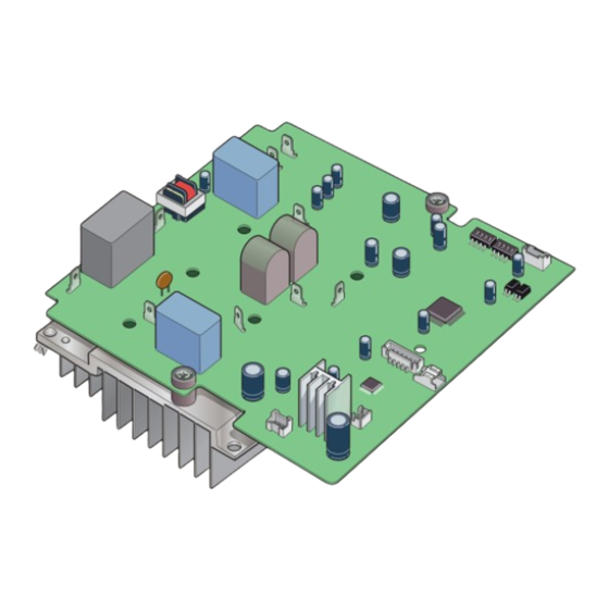
Svenska Allmänt Denna serviceinstruktion beskriver byte av inverterkort (PWB2) i AMS 10-8 / F2040-8. KORT- OCH KABEL-KIT AMS 10-8 / F2040-8 PWB 2 och drossel med kablage 718 499 KOMPONENTPLACERING ELKOMPONENTER PWB1 Kontrollkort PWB2 Inverterkort PWB3 Filterkort Anslutningsplint, inkommande matning och kom-... -
Page 5: Elinkoppling
Demontera reaktorn som är placerad på plåten ne- elektriker. danför ellådan. GÖR SÅ HÄR Gör AMS 10-8 / F2040-8 / VVM / SMO spänningslö- Vänta minst en minut för att kondensatorer ska lad- das ur. Anslut ESD-skyddsarmband. Demontera kontrollkortet PWB1. Lossa PWB1 ge- nom att skruva loss de fyra skruvarna. - Page 6 Demontera (bryt loss) de grå fästena (3 st). Nya Fäst det nya inverterkortet PWB2 och kylflänsen fästen finns bipackade. De sitter fast med dubbelhäf- med de fyra skruvarna i hörnen. Använd gärna en tande tejp. magnetisk skruvmejsel. Montera de tre nya grå kabelfästena med den dub- Skruva loss PWB2.
- Page 7 RD, WH och BK placeras på det nya kortet i rad, se beteckningarna. Återmontera alla kablarna enligt tidigare placering, se beteckningarna. Återanslut kablarna T21 (röd) och T22 (vit). | SE...
- Page 8 Återanslut kablarna T26 (röd) och T27 (blå), se be- teckningarna. Använd kabelfästena för att få ordning på kablarna och hålla dem på plats. De tre skruvarna som reaktorn satt med ska återan- Tryck fast det vita kabelfästet på kortet. vändas för att montera dit den nya fästplåten. Haka fast den nya reaktorn i utskärningen på...
- Page 9 (T52 och T62) och kontakter. Fäst kontrollkortet med de fyra skruvarna. en gul kabel (T51) på kretskortet. Samla kablarna i närmaste grå fäste. Spänningssätt först AMS 10-8 / F2040-8 och sedan VVM / SMO. | SE...
- Page 10 MARKERAT KORT OCH KABLAGE SKA ERSÄTTAS ELSCHEMA AMS 10-8 / F2040-8 T21 T22 CNO1 (WH) CNG2 CNG1 (WH) (BK) (BK) PWB1 PWB2 INVERTER CNI1 CNI2 (WH) (WH) CNI3 CNI4 (WH) (WH) CNA1 (WH) CNA2 (WH) (WH) | SE...
-
Page 11: English
English General These service instructions describe how to replace the inverter board (PWB2) in AMS 10-8 / F2040-8. BOARD AND CABLE KIT AMS 10-8 / F2040-8 PWB 2 and choke with wiring 718 499 COMPONENT POSITIONS ELECTRICAL COMPONENTS PWB1 Control board... -
Page 12: Electrical Connection
DO AS FOLLOWS: Disconnect the power to AMS 10-8 / F2040-8 / VVM / SMO. Wait for at least one minute for the capacitors to discharge. Connect an ESD bracelet. Remove the control board PWB1. Release PWB1 by unscrewing the four screws. - Page 13 Remove (break off) the grey mounts (3 pcs). New Secure the new inverter board PWB2 and the cool- mounts are enclosed. They are attached with double- ing fin with the four screws in the corners. It is best sided tape. to use a magnetic screwdriver.
- Page 14 RD, WH and BK are placed on the new board in a row, see the designations. Reinstall all the cables in their previous positions, see the designations. Reconnect the cables T21 (red) and T22 (white). | GB...
- Page 15 Reconnect the cables T26 (red) and T27 (blue), see the designations. Use the cable mounts to get the cables tidy and to keep them in place. The three screws that were securing the reactor Press the white cable mount onto the board. should be reused to install the new mounting plate.
- Page 16 Secure the control board with the four screws. and T62) and one yellow cable (T51) on the circuit board. Gather the cables in the nearest grey mount. Supply first AMS 10-8 / F2040-8 and then VVM / SMO with power. | GB...
- Page 17 MARKED BOARD AND WIRING MUST BE REPLACED ELECTRICAL WIRING DIAGRAM AMS 10-8 / F2040-8 T21 T22 CNO1 (WH) CNG2 CNG1 (WH) (BK) (BK) PWB1 PWB2 INVERTER CNI1 CNI2 (WH) (WH) CNI4 CNI3 (WH) (WH) CNA1 (WH) CNA2 (WH) (WH) | GB...
-
Page 18: Deutsch
Deutsch Allgemeines In dieser Serviceanleitung wird der Wechsel der Inver- terplatine (PWB2) in AMS 10-8 / F2040-8 beschrieben. PLATINEN- UND KABELSATZ AMS 10-8 / F2040-8 PWB 2 und Drossel mit Verkabe- 718 499 lung POSITION DER KOMPONENTEN ELEKTRISCHE KOMPONENTEN PWB1... -
Page 19: Elektrischer Anschluss
Demontieren Sie die Drossel, die sich am Blech unter dem Schaltschrank befindet. VORGEHENSWEISE Unterbrechen Sie die Spannungsversorgung für AMS 10-8 / F2040-8 / VVM / SMO. Warten Sie mindestens eine Minute, damit sich die Kondensatoren entladen. Schließen Sie ein ESD-Schutzarmband an. - Page 20 Demontieren Sie (durch Abbrechen) die grauen Befestigen Sie die neue Inverterplatine PWB2 und Halterungen (3 St.). Neue Halterungen befinden sich den Kühlkörper mit den vier Schrauben in den Ecken. im Lieferumfang. Sie sind mit doppelseitigem Klebe- Es wird die Verwendung eines magnetischen band befestigt.
- Page 21 RD, WH und BK werden auf der neuen Platine in Reihe platziert, siehe Bezeichnungen. Bringen Sie alle Kabel gemäß der vorherigen Platzie- rung wieder an, siehe Bezeichnungen. Schließen Sie die Kabel T21 (rot) und T22 (weiß) wieder an. | DE...
- Page 22 Schließen Sie die Kabel T26 (rot) und T27 (blau) wieder an, siehe Bezeichnungen. Verwenden Sie die Kabelbefestigung zum Ordnen und Fixieren der Kabel. Die drei Schrauben für die Befestigung der Drossel Drücken Sie die weiße Kabelbefestigung auf der sind bei der Montage des neuen Befestigungsblechs Platine fest.
- Page 23 Kabel (T52 und T62) sowie ein gelbes tine mit den vier Schrauben. Kabel (T51). Fassen Sie die Kabel an der nächstgele- genen grauen Halterung zusammen. Versorgen Sie zunächst AMS 10-8 / F2040-8 und dann VVM / SMO mit Spannung. | DE...
- Page 24 DIE GEKENNZEICHNETE PLATINE UND VERKABELUNG MUSS ERSETZT WERDEN. SCHALTPLAN AMS 10-8 / F2040-8 T21 T22 CNO1 (WH) CNG2 CNG1 (WH) (BK) (BK) PWB1 PWB2 INVERTER CNI1 CNI2 (WH) (WH) CNI3 CNI4 (WH) (WH) CNA1 (WH) CNA2 (WH) (WH) | DE...
-
Page 25: Wiring Diagram
Wiring diagram AMS 10-8 / F2040-8 POWER SOURCE 230V ~50Hz 230V 50Hz F(20A) T2 T1 Y/GN F6 (5A) FM01 CNO2 (WH) (4A) 6 5 4 3 2 1 4 3 2 1 7 6 5 4 1 CNO1 CNW2 CNEEV2... - Page 28 WS version: a515 (working edition) Publish date: 2018-05-03 08:34 This manual is a publication from NIBE Energy Systems. All product illustrations, facts and specifications are based on current information at the time of the publication’s approval. NIBE Energy Systems makes reservations for any factual or printing errors in this manual.
Need help?
Do you have a question about the AMS 10-8 and is the answer not in the manual?
Questions and answers