Table of Contents
Advertisement
Quick Links
Union
Installation Guide
For Model:
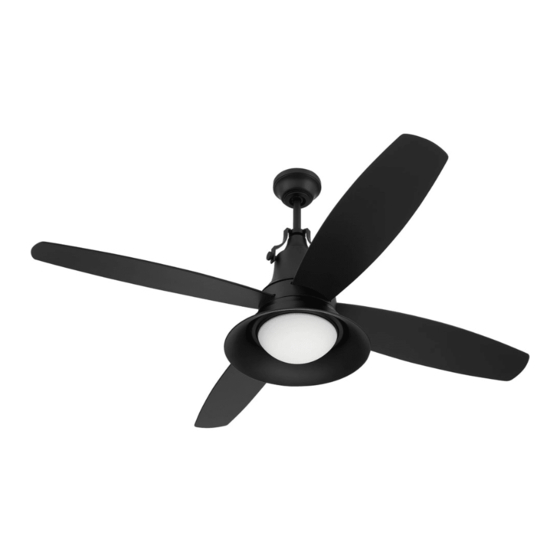
UN52-LED
WARNING:
DC Motor will not
operate until blades
are installed
For
Damp Location
net weight of fan: 17.08 lb (7.75 kg)
READ THESE INSTRUCTIONS AND
Table of Contents:
Safety Tips. pg. 2
Unpacking Your Fan. pg. 3
Parts Inventory. pg. 3
Installation Preparation. pg. 4
Hanging Bracket Installation. pg. 4
Fan Assembly. pgs. 5 - 6
Wiring. pg. 7
Canopy Assembly. pg. 8
Blade Assembly. pg. 8
Light Kit Assembly. pg. 9
Handheld Remote Control Assembly. pg. 10
Remote/Wall Control Operation. pg. 12
Testing Your Fan. pg. 12
Troubleshooting. pg. 13
Warranty. pg. 13
Parts Replacement. pg. 13
page 1
SAVE THEM FOR FUTURE USE
PRINTED IN CHINA
Advertisement
Table of Contents

Related Manuals for Craftmade Union


Summary of Contents for Craftmade Union
-
Page 1: Table Of Contents
READ THESE INSTRUCTIONS AND SAVE THEM FOR FUTURE USE Union Installation Guide For Model: Table of Contents: UN52-LED Safety Tips. pg. 2 Unpacking Your Fan. pg. 3 Parts Inventory. pg. 3 WARNING: Installation Preparation. pg. 4 DC Motor will not Hanging Bracket Installation. -
Page 2: Safety Tips
(2) this LED light kit must accept any interference received, including interference that may cause undesired operation. Distributed by: Craftmade, 3901 S. 20th Avenue, DFW Airport, TX 75261; 1-800-486-4892. NOTE: The important safety precautions and instructions appearing in the manual are not meant to cover all possible conditions and situations that may occur. -
Page 3: Unpacking Your Fan
1. Unpacking Your Fan. Carefully open the packaging. Remove items from Styrofoam inserts. Remove motor housing and place on carpet or Styrofoam to avoid damage to finish. Do not discard fan carton or Styrofoam inserts should this fan need to be returned for repairs. Check against parts inventory that all parts have been included. -
Page 4: Installation Preparation
3. Installation Preparation. blade edge To prevent personal injury and damage, ensure that the hanging location allows the blades a inches 7 feet (2.13 m) (76 cm) clearance of 7 feet (2.13m) from the floor and 30in. (76cm) from any wall or obstruction. This fan is suitable for room sizes up to 400 square 12ft. -
Page 5: Fan Assembly. Pgs
stop pin 5. Fan Assembly. set screw Remove hanging ball from downrod provided by hanging ball loosening set screw on hanging ball. Lower hanging ball and remove stop pin and then slide hanging ball off of the downrod. [Refer to diagram 1.] diagram 1 Loosen yoke set screws and nuts at top of motor electrical wiring... - Page 6 5. Fan Assembly. (cont.) safety cable Thread safety cable and wires through hanging ball; weatherproof then slide hanging ball over downrod--the top of the hanging downrod should be noted as having a set screw hole; ball cover use this hole when setting the set screw. Insert stop electrical wiring pin into top of downrod and raise hanging ball.
-
Page 7: Wiring
6. Wiring. WARNING: Turn off circuit breakers to current fixture from breaker panel and be sure switch is turned to the OFF position. white supply wire ground (green or bare) CAUTION: Be sure outlet box is properly grounded and black supply wire that a ground wire (GREEN or Bare) is present. -
Page 8: Canopy Assembly
7. Canopy Assembly. Remove 2 screws on underside of hanging bracket. hanging bracket Lift canopy to hanging bracket. Align holes in canopy with holes in hanging bracket. While holding canopy canopy in place, slide anti-sway adapter up to canopy. Align holes in anti-sway adapter with holes anti-sway in bottom of canopy and then re-insert the screws adapter... -
Page 9: Light Kit Assembly
9. Light Kit Assembly. motor housing Remove 1 screw from motor plate on underside of motor and partially loosen the other 2 screws. Align slotted holes in fitter plate with loosened screws in motor plate, allowing molex plugs screws from motor housing to come through hole in motor plate middle of fitter plate. -
Page 10: Handheld Remote Control Assembly
10. Handheld Remote Control Assembly. remote IN ORDER TO USE THE HANDHELD REMOTE control CONTROL, PLEASE CONTINUE WITH SECTION 10 cover for remote control assembly instructions. If you have already installed the wall control but do not wish to use the handheld remote control, please proceed to Section 11. -
Page 11: Automated Learning Process./Activating Code
11. Automated Learning Process./Activating Code. CAUTION: The wall and/or handheld remote wall control control can be programmed to multiple receivers or fans. If this is not desired, turn wall switch off to any other programmable receiver or fan. I I I Restore electrical power and then, if using wall control, set slider switch on wall control to the ON position. -
Page 12: Remote/Wall Control Operation
12. Remote/Wall Control Operation. handheld wall control remote control IMPORTANT: Handheld remote control and wall control must be I I I SYNCHRONIZED with fan in order to properly function. Fan SPEED buttons -1: Use to control the ceiling fan speed 1-6 Fan OFF button - 2: Use to turn the fan off REVERSE function button - 3:... -
Page 13: Troubleshooting
Service at 1-800-486-4892 to arrange for return of fan. 1. Check power to wall switch/wall control. Return fan, shipping prepaid, to Craftmade. We will repair 2. Verify that wall control is wired properly. or ship you a replacement fan, and we will pay the return (optional use) shipping cost.
Need help?
Do you have a question about the Union and is the answer not in the manual?
Questions and answers