Table of Contents
Advertisement
Available languages
Available languages
Quick Links
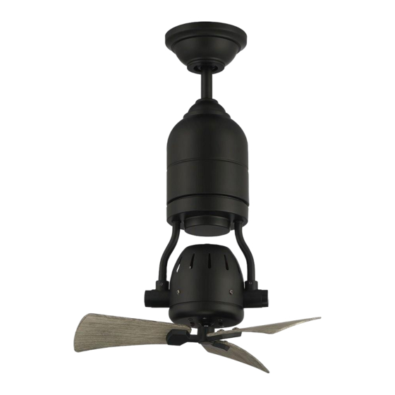
Bellows Uno
Installation Guide
For Model:
BW318
3170356
APPROVED FOR
DAMP LOCATION
net weight of fan: 11.46 lb (5.2 kg)
READ THESE INSTRUCTIONS AND
SAVE THEM FOR FUTURE USE
Table of Contents:
Safety Tips. pg. 2
Unpacking Your Fan. pg. 3
Parts Inventory. pg. 3
Installation Preparation. pg. 4
Hanging Bracket Installation. pg. 4
Fan Assembly. pgs. 5 - 6
Wiring. pgs. 6 - 7
Canopy Assembly. pg. 7
pg. 8
Remote Control Operation. pg. 9
Testing Your Fan. pg. 9
Troubleshooting. pg. 10
Warranty. pg. 10
Parts Replacement. pg. 10
page 1
PRINTED IN CHINA
Advertisement
Chapters
Table of Contents

Related Manuals for Craftmade Bellows Uno BW318


Summary of Contents for Craftmade Bellows Uno BW318
-
Page 1: Table Of Contents
READ THESE INSTRUCTIONS AND SAVE THEM FOR FUTURE USE Bellows Uno Installation Guide For Model: BW318 Table of Contents: Safety Tips. pg. 2 Unpacking Your Fan. pg. 3 Parts Inventory. pg. 3 Installation Preparation. pg. 4 Hanging Bracket Installation. pg. 4 Fan Assembly. -
Page 2: Safety Tips
SAFETY TIPS. WARNING: To reduce the risk of electrical shock, turn off the electricity to the fan at the main fuse box or circuit panel before you begin the fan installation or before servicing the fan or installing accessories. READ ALL INSTRUCTIONS AND SAFETY INFORMATION CAREFULLY BEFORE INSTALLING YOUR FAN AND SAVE THESE INSTRUCTIONS. -
Page 3: Unpacking Your Fan
1. Unpacking Your Fan. Carefully open the packaging. Remove items from Styrofoam inserts. Remove motor assembly and place on carpet or Styrofoam to avoid damage to finish. Do not discard fan carton or Styrofoam inserts should this fan need to be returned for repairs. -
Page 4: Installation Preparation
3. Installation Preparation. blade edge To prevent personal injury and damage, ensure that the hanging location of the fan allows the fan cage a inches 10 feet clearance of 10 feet (3.05m) from the floor and that (3.05m) (76cm) the edges of the fan cage will be at least 30in. (76 cm) from any wall or obstruction. -
Page 5: Fan Assembly. Pgs
5. Fan Assembly. set screw stop pin Remove hanging ball from downrod provided by loosening set screw on hanging ball. Lower hanging hanging ball ball and remove stop pin and then slide hanging ball off of the downrod. [Refer to diagram 1.] Loosen yoke set screws and nuts at top of motor diagram 1 assembly. -
Page 6: Wiring. Pgs
5. Fan Assembly. (cont.) With the hanging bracket secured to the outlet box and safety cable loop wood able to support the fan, you are now ready to hang your ceiling fan. Grab the fan firmly with two hands. Slide downrod joist through opening in hanging bracket and let hanging ball rest on the hanging bracket. -
Page 7: Canopy Assembly
6. Wiring. (cont.) Modifications not approved by the party responsible for compliance could void the user's authority to operate the equipment. [PLEASE NOTE: Wall and/or handheld *NOTE: This equipment has been tested and found to comply with the limits for a Class B digital device, pursuant to Part 15 of the FCC Rules. -
Page 8: Assembly Of Handheld Remote Control
8. Assembly of Handheld Remote Control. remote control IN ORDER TO USE THE HANDHELD REMOTE cover CONTROL, PLEASE CONTINUE WITH SECTION 8 for remote control assembly instructions. If you have already installed the wall control but do not wish to use the handheld remote control, please proceed to Section 9. -
Page 9: Automated Learning Process./Activating Code
9. Automated Learning Process./Activating Code. CAUTION: The wall and/or handheld remote control can be programmed to multiple receivers or fans. If this is not desired, turn wall switch off to any other programmable receiver or fan. Restore electrical power and then, if using wall control, set slider switch on wall control to the ON position. -
Page 10: Troubleshooting
Service at 1-800-486-4892 to arrange for return of fan. 1. Check wall switch to fan/wall control. Return fan, shipping prepaid, to Craftmade. We will repair 2. Check to be sure wall control (optional use) is or ship you a replacement fan, and we will pay the return wired properly. - Page 11 LEER ESTAS INSTRUCCIONES Y GUARDARLAS PARA UTILIZACIÓN FUTURA Bellows Uno Guía de instalación Para modelo: BW318 Índice de materias: Sugerencias de seguridad. Pág. 2 Desempaquetado del ventilador. Pág. 3 Inventario de piezas. Pág. 3 Preparación para la instalación. Pág. 4 Instalación del soporte de montaje.
-
Page 12: Sugerencias De Seguridad. Pág
SUGERENCIAS DE SEGURIDAD. ADVERTENCIA: para evitar la posibilidad de una descarga eléctrica, desconectar la corriente en la caja de fusibles principal o el interruptor protector antes de iniciar la instalación del ventilador o antes de repararlo o instalar accesorios. LEER TODAS LAS INSTRUCCIONES E INFORMACIÓN DE SEGURIDAD CUIDADOSAMENTE ANTES DE INSTALAR SU VENTILADOR Y GUARDAR ESTAS INSTRUCCIONES. -
Page 13: Desempaquetado Del Ventilador. Pág
1. Desempaquetado del ventilador. Abrir el empaque cuidadosamente. Sacar los artículos del embalaje. Sacar la unidad del motor y ponerla en una alfombra o en el embalaje para evitar rayar el acabado. Guardar la caja de cartón o el empaquetamiento original en caso de que tenga que mandar el ventilador para alguna reparación. -
Page 14: Preparación Para La Instalación. Pág
3. Preparación para la instalación. Para prevenir daño corporal y otros daños, estar borde del aspa seguro de que el lugar en donde va a colgar el 76cm ventilador le permite un espacio libre de 3,05m (10 pies) entre la caja protectora del ventilador y el 3,05m pulg.) piso y 76cm (30 pulg.) entre el borde de la caja... -
Page 15: Ensamblaje Del Ventilador. Págs
perno 5. Ensamblaje del ventilador. de tope tornillo de fijación Quitar la bola que sirve para colgar del tubo provisto aflojando el tornillo de fijación de la bola que sirve para colgar. Bajar la bola que sirve para colgar y sacar el perno de bola que tope y luego quitar la bola que sirve para colgar deslizándola. -
Page 16: Instalación Eléctrica. Págs
5. Ensamblaje del ventilador. (cont.) bucle del cable de seguridad Ya que esté sujetado el soporte de montaje a la caja de salida y capaz de apoyar el ventilador, usted está listo para colgar el viga de ventilador. Agarrar el ventilador firmemente con las dos manos. madera Deslizar el tubo por la abertura del soporte de montaje y dejar que se detenga la bola en el soporte de montaje. -
Page 17: Colocación De La Cubierta Decorativa. Pág
Las modificaciones no aprobadas por la parte responsable de la conformidad 6. Instalación eléctrica. (cont.) podrían invalidar la autorización del usuario para manejar el equipo. *NOTA: Se han hecho pruebas en este equipo y se ha comprobado que cumple con los límites para un [FAVOR DE DARSE CUENTA: hay que utilizar el aparato digital de clase B, de acuerdo con la Parte 15 de las Reglas de la FCC. -
Page 18: Ensamblaje Del Control Remoto De Mano
8. Ensamblaje del control remoto de mano. cubierta del control remoto PARA PODER UTILIZAR EL CONTROL REMOTO DE MANO, FAVOR DE SEGUIR CON LA SECCIÓN 8 para armar el control remoto. Si ya se instaló el control de pared pero no desea utilizar el control remoto de mano, favor de pasar a la sección 9. -
Page 19: Proceso De Aprendizaje Automático./ El Activar El Código. Pág
9. Proceso de aprendizaje automático./El activar el código. PRECAUCIÓN: se puede programar el control de pared/control remoto de mano para usar con varios receptores o ventiladores. Si no desea hacer esto, apagar el interruptor de cualquier otro receptor o ventilador programable. Conectar la electricidad y luego, si se instaló... - Page 20 Problema: el ventilador no funciona. debido a defectos en los materiales o trabajo manual. Soluciones: Comunicarse con el Servicio al cliente de CRAFTMADE al 1. Inspeccionar el interruptor de pared del 1-800-486-4892 para acordar el reenvío del ventilador. ventilador/control de pared.
Need help?
Do you have a question about the Bellows Uno BW318 and is the answer not in the manual?
Questions and answers