Table of Contents
Advertisement
Quick Links
O
peratiOn and
D
iaphragm
D
esign
a
O
ir
perateD
V
alVe
fOr
/
/
/
c l
c m
ch
Ol/Om/Oh
mODel OperatOrs
10V
sW
10sm
20sm
30Vm
40Vm
60Vm
100Vm
series ValVes
Parker Autoclave Engineers
Instrumentation Products Div.
8325 Hessinger Dr.
Erie, PA 16509-4679
Tel: 814-860-5700
Fax: 814-860-5811
www.autoclave.com
M
aintenance
M
anual
ISO-9001 Certified
Advertisement
Table of Contents

Subscribe to Our Youtube Channel
Related Manuals for Parker Autoclave Engineers 10V Series


Summary of Contents for Parker Autoclave Engineers 10V Series
- Page 1 Ol/Om/Oh mODel OperatOrs 10sm 20sm 30Vm 40Vm 60Vm 100Vm series ValVes Parker Autoclave Engineers Instrumentation Products Div. 8325 Hessinger Dr. Erie, PA 16509-4679 Tel: 814-860-5700 Fax: 814-860-5811 ISO-9001 Certified www.autoclave.com...
-
Page 2: Installation
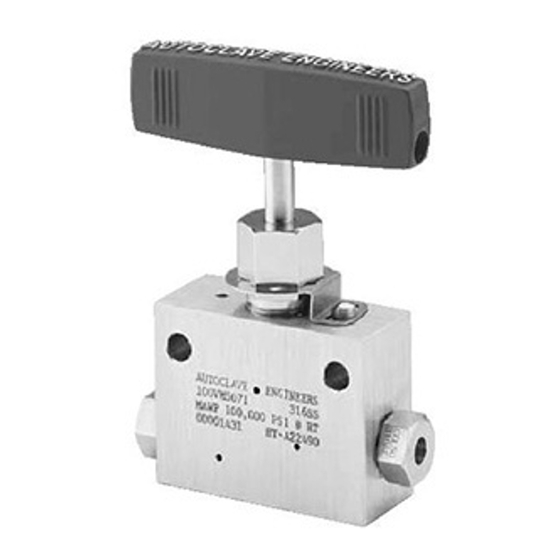
INSTALLATION All valves are factory adjusted and tested at the pressure marked on the operator label. Refer to Parker Autoclave Engineers’ Valves, Fittings and Tubing Catalog (installation section) for proper tubing connection installation. The air supply connection on the operator is 1/8” NPT. The recommended value for air pressure at the maximum valve operating pressures is shown on the operator label. -
Page 3: Packing Adjustment
SPRING ADJUSTMENT - OL, OM and OH VALVES ONLY On some sizes of the OL, OM and OH operators, the spring limits the travel at the maximum pressures. This affects the flow capacity of the valve. See the Air Operator Sizing Data in the Valve Actuators Section of the VFT Catalog for actual system travel and flow coefficient. If a longer stem travel is desired when the operating pressure is less than the maximum, then this should be requested at the time of order so that the valve will be properly adjusted at the factory. - Page 4 PACKING OR STEM REPLACEMENT To change packing or stem, follow the steps listed below. Relieve all pressure from the valve and operator. OL, OM and OH Valves Only: Loosen the jam nut on top of the spring housing, then loosen the screw until all spring compression is relieved.
-
Page 5: Seat Replacement
SEAT REPLACEMENT (Replacement Seat Valves) When the seat requires replacement, use the following procedure. Relieve all pressure from the valve. (OL, OM, and OH valves only) Loosen the jam nut on top of the spring housing then loosen the screw until all spring compression is relieved. - Page 6 The stem may be attached to the diaphragm head in a number of different ways. Follow one of the below procedures and refer to the indicated illustration that applies to the operator being repaired. • (Figure 4) Loosen the hex socket set screw (Item #21) from the top of the diaphragm head and unscrew the stem.
- Page 7 10. Place a new diaphragm in the lower housing, making sure that it fits into the recess, as shown in Figure 1. Refer to the replacement parts list for the proper diaphragm part number. Place the diaphragm head over the diaphragm, place the washer onto the stem, push the stem through the packing gland, o-ring retainer and diaphragm, and attach it into the diaphragm head.
- Page 8 Follow the instructions in Section 4.0, Steps 10-12 to install the operator to the body. SERVICE For service, contact the Parker Autoclave Engineers Representative in your area, or FAX Parker Autoclave Engineers’ Customer Support at 1-814-860-5811.
- Page 9 REPLACEMENT PARTS LISTS - Diaphragm Part Number VALVE SERIES 10V2 3030-1414 105A-0226 3030-1414 102A-0326 10V4 3030-1414 103A-0326 3030-1414 102A-0326 10V6 3030-1414 103A-0326 3030-1414 102A-0326 10V8 103A-0326 102A-0326 105A-0326 102A-0326 105A-0326 102A-0326 105A-0326 102A-0326 10/20SM4 105A-0326 3100-2023 102A-0326 3100-2023 10/20SM6 105A-0326 3100-2023 102A-0326 3100-2023...
- Page 10 DIAPHRAGM AIR OPERATED VALVES - Installation Summary Chart - Air-to-Close Packing Gland Packing Gland Seat Retainer Tube Gland Tube Gland VALVE SERIES Hex Size Torque Torque Hex Size Torque ft-lbs (Nm)1 in (mm) ft-lbs (Nm) in (mm) ft-lbs (Nm) 13/16 (20.6) 35 (47.4) 15 (20.3) 13/16 (20.6)
- Page 11 DIAPHRAGM AIR OPERATED VALVES - Installation Summary Chart - Air-to-Open VALVE SERIES Packing Tube Packing Seat Spring Equiv- Tube Gland Gland Gland Retainer Pre- alent Gland Hex Size Hex Size Torque Torque Compression Turns Torque in (mm) ft-lbs ft-lbs in (mm) in (mm) ft-lbs (Nm)
- Page 12 figure #1...
- Page 13 figure #2...
-
Page 14: Set Screw
HEX NUT -CH ONLY figure #3 SET SCREW WASHER figure #4 HEX NUT WASHER HEX NUT (-OH ONLY) figure #5... -
Page 15: Retaining Ring
RETAINING RING O-RING RETAINER O-RING P-6002 (UNIF #108) O-RING P-0885 (UNIF #112) figure #6 OM OPERATOR 1/8” 1OV, ALL SW 8 20SM VALVES O-RING P-0885 (UNIF #112) SLEEVE O-RING P-0847 (UNIF #007) figure #7 OL OPERATORS CAUTION: While testing has shown O-rings to provide satisfactory service life, both cyclic and shelf life may vary widely with differing service conditions, properties of reactants, pressure and temperature cycling and age of the O- ring, FREQUENT INSPECTIONS SHOULD BE MADE to detect any deterioration, and O-rings replaced as required. -
Page 16: Packing Gland
RETAINING RING O-RING P-0885 SLEEVE (UNIF #112) O-RING P-0847 (UNIF #007) figure #8 OM OPERATOR 1/4, 3/8, 1/2 1OV & ALL 30VM & 60VM VALVES O-RING P-0867 (UNIF #110) OR P-0848 (UNIF #009) PACKING GLAND HEX NUT figure #9 OH OPERATORS CAUTION: While testing has shown O-rings to provide satisfactory service life, both cyclic and shelf life may vary widely with differing service conditions, properties of reactants, pressure and temperature cycling and age of the O- ring, FREQUENT INSPECTIONS SHOULD BE MADE to detect any deterioration, and O-rings replaced as required. - Page 17 *Maximum pressure rating is based on the lowest rating of any component. Actual working pressure may be determined by tubing pressure rating, if lower. All dimensions for reference only and subject to change. For prompt service, Parker Autoclave stocks select products. Consult your local representative.
- Page 18 *Maximum pressure rating is based on the lowest rating of any component. Actual working pressure may be determined by tubing pressure rating, if lower. All dimensions for reference only and subject to change. For prompt service, Parker Autoclave stocks select products. Consult your local representative.
- Page 19 Air-to-Close - Series 60VM Valves Maximum Stem Travel Flow Valve System Pressure KSI (Mpa) Operator Duty Pressure in (mm) Coefficient** Series psi (bar)* 1-20 (6.89-137.89) (172.37) (206.84) (241.31) (275.79) (310.26) (344.73) (379.21) (413.68) 60,000 0.25 0.08 Medium Duty 60VM4 (2.07) (2.07) (2.41) (3.10)
- Page 20 *Maximum pressure rating is based on the lowest rating of any component. Actual working pressure may be determined by tubing pressure rating, if lower. All dimensions for reference only and subject to change. For prompt service, Parker Autoclave stocks select products. Consult your local representative.
- Page 21 *Maximum pressure rating is based on the lowest rating of any component. Actual working pressure may be determined by tubing pressure rating, if lower. All dimensions for reference only and subject to change. For prompt service, Parker Autoclave stocks select products. Consult your local representative.
- Page 22 All dimensions for reference only and subject to change. stem travel (lowest system pressure) to minimum travel (highest system pressure). For prompt service, Parker Autoclave stocks select products. Consult your local representative. *Maximum pressure rating is based on the lowest rating of any component.
- Page 23 *Maximum pressure rating is based on the lowest rating of any component. Actual working pressure may be determined by tubing pressure rating, if lower. All dimensions for reference only and subject to change. For prompt service, Parker Autoclave stocks select products. Consult your local representative.
- Page 24 FAILURE, IMPROPER SELECTION OR IMPROPER USE OF THE PRODUCTS AND/OR SYSTEMS DESCRIBED HEREIN OR RELATED ITEMS CAN CAUSE DEATH, PERSONAL INJURY AND PROPERTY DAMAGE. This document and other information from Parker Hannifin Corporation, its subsidiaries and authorized distributors provide product and/or system options for further investigation by users having technical expertise.
Need help?
Do you have a question about the Autoclave Engineers 10V Series and is the answer not in the manual?
Questions and answers