Table of Contents
Advertisement
Quick Links
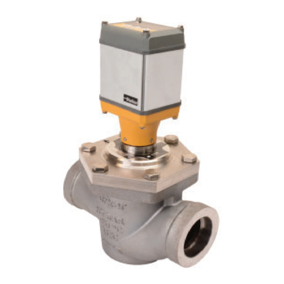
Parker Electronic Valve
Product Bulletin 24-00 D
Type: PEV
Purpose:
The PEV series of electronic
modulating valves off er superior
control for refrigeration systems.
They ensure precise fl ow regulation
for liquid level, expansion,
superheat, and temperature control
applications.
Constructed from stainless steel
and plated steel, these valves resist
corrosion in harsh environments.
The weld-in feature minimizes
connection leaks.
With higher working pressure,
a broader temperature range,
and greater fl ow capacities
than traditional R/S products,
these valves deliver long-term
performance with replacedable
modular components.
Product Features:
• Suitable for Ammonia, CO
and other common refrigerants.
• Stainless steel and plated steel construction increases
product life cycle.
• Lightweight construction.
• Cartridge based design simplifi es service and eliminates
body wear.
• Works with any 4-20 mA controller.
P
E
A
L
R
E
K
C
E
T
R
R
O
N
I
C
, R-134a, R-404A, R-410A
2
V
A
L
V
E
• Alarm notifi cation.
• Interchangeable cartridge assembly with other
P-Series off erings.
• Bright Seven-Segment LED Display.
• Password protection prevents tampering.
• IP67/NEMA 6 rated.
• Complies with ASME B31.5, PED 2014/68/EU, and
ANSI/IIAR 3-2022.
Advertisement
Table of Contents

Related Manuals for Parker PEV Series


Summary of Contents for Parker PEV Series
- Page 1 Parker Electronic Valve Product Bulletin 24-00 D Type: PEV Purpose: The PEV series of electronic modulating valves off er superior control for refrigeration systems. They ensure precise fl ow regulation for liquid level, expansion, superheat, and temperature control applications. Constructed from stainless steel and plated steel, these valves resist corrosion in harsh environments.
-
Page 2: Table Of Contents
23.0 50.6 Function and Design The Parker Electronic Valve (PEV) is an electronically controlled valve The PEV positions the valve to a user-defi ned state during power loss that modulates refrigerant fl ow in refrigeration applications. It excels in if backup power is supplied (see electrical section for details). Post- scenarios with signifi... -
Page 3: Application Example
PEV Bulletin 24-00 D - Page 3 Application Example HBLT-C1-ENC Low Pressure (LP) Liquid Level Control Electronic Valve Liquid Level Controller Liquid Level Transmitter HBLT- Strainer Receiver 149µm (100 mesh) LLSS Pump separator installed with an HBLT- analog liquid level transmitter probe for continuous level control of the vessel. -
Page 4: Material List
Page 4 - PEV Bulletin 24-00 D Material List 20 to 40mm ( ⁄ to 1- ⁄ ") Material Item Description 20 to 25mm 32 to 40mm (pcs) (¾ to 1") (1-¼ to 1-½ ") PEV Actuator Aluminum, Resin, Silicone Screws, Actuator Stainless Steel - M4 Bolts, Port Plate... -
Page 5: Pev 50 To 80 ( To 3")
PEV Bulletin 24-00 D - Page 5 Material List 50 to 80mm (2 to 3") Material Item Description 50mm 65 to 80mm (pcs) (2") (2-½ to 3") PEV Actuator Aluminum, Resin, Silicone Screws, Actuator Stainless Steel - M4 Bolts, Port Plate Stainless Steel - M12 Stainless Steel - M16 Cap, Plug... -
Page 6: Installation Instructions
Page 6 - PEV Bulletin 24-00 D The valve should be disassembled before welding to prevent damage to Installation Instructions o-rings and Tefl on (PTFE) components. First remove the port plate by All personnel working on valves must be qualifi ed to work on unbolting the bolts as shown in Figure 2. -
Page 7: Port Plate Bolt And Torque Recommendations
PEV Bulletin 24-00 D - Page 7 Installers need to follow a WPS (Welding Procedure Specifi cation) for all welding. Both the procedure and welder must be qualifi ed to perform that procedure. The codes applicable to the welding of socket weld valves require that the pipe be inserted into the socket until bottomed against the stop, then backed out approximately ⁄... -
Page 8: Electrical
Backup power can be supplied through the 8-pin cable (Pin 2 - UPS Backup Power Supply) or the 4-Pin connector on the actuator. Contact Parker for wiring specifi cations if using the 4-Pin connector. For system wiring the PEV comes with a 3 meters (9 feet) cable. -
Page 9: User Interface Guide
PEV Bulletin 24-00 D - Page 9 User Interface Guide Select Move selection down Move selection up Menu and Level Navigation Guide % Open Screen % Open Press Press Press Level 1 Screen if password if password is enabled isn’t enabled Level 1 Level 2 Screen Press... -
Page 10: Quick Start Instructions
Page 10 - PEV Bulletin 24-00 D Quick Start Instructions PEV Quick Start Instructions Steps Display Setup Instructions Connect the 8-pin cable to an appropriate power source and controller and apply 24 VDC to the PEV. During initial confi guration, the PEV will display 'A01' (which indicates no valve selected). Press to get to the level 1 parameters. -
Page 11: Software Parameters
PEV Bulletin 24-00 D - Page 11 Software Parameters PEV Software Parameters Level 1 Level 1 Level 2 Default Level 2 Value Description PEV Valve % Open position is displayed during normal operation Value Password Protected. Default Password = ‘P.0.5.’ At initial startup, ‘A01’... -
Page 12: Alarm List
Page 12 - PEV Bulletin 24-00 D Alarm List PEV Alarm List Alarm Text Description Comments During startup, after a reset to default settings, or any time a valve size is not selected, the alarm will be sent out No valve size selected until a valve size is chosen. -
Page 13: Connection Type - Dimensions
PEV Bulletin 24-00 D - Page 13 Connection Type - Dimensions Port Size Connection inch inch inch ⁄ " 27.3 1.075 ⁄ 1" 34.0 1.340 12.7 0.50 ⁄ " 42.8 1.685 ⁄ " 42.8 1.685 Socket Weld (SW) 12.7 0.50 ⁄... -
Page 14: Nameplate Information
Page 14 - PEV Bulletin 24-00 D Nameplate Information Port Size Name Plate Image Name Plate 1. Connection Size 2. Connection Type 20 mm to 25 mm 3. Port Size ⁄ " to 1") 4. Date Code 5. Valve Model Number (Smart Part Number) 6. -
Page 15: Maintenance
All personnel working on valves must be qualifi ed to work on refrigeration systems. Any person intending to service a Seat valve should read the appropriate product and safety bulletin before performing any work on Parker products. Capacity Plug Housing Additional points to consider: Figure 13: Removal of the PEV Port Plate Assembly. -
Page 16: Parts Kit Reference
Page 16 - PEV Bulletin 24-00 D Parts Kit Reference 20 to 40mm ( ⁄ to 1- ⁄ ") PEV Parts Kit Reference 20 to 25 (¾ to 1") Port Size Item Description Kit Description 20 mm 25 mm ⁄ ") (1") Actuator, Assembly... -
Page 17: Pev 50 To 80 ( To ")
PEV Bulletin 24-00 D - Page 17 Parts Kit Reference 50 to 80mm (2 to 3") PEV Parts Kit Reference 50 to 80 (2 to 3") Port Size Item Description Kit Description 50 mm 65 mm 80 mm (2") ⁄ ") (3") Actuator, Assembly... - Page 18 Page 18 - PEV Bulletin 24-00 D HBLT-C1 Liquid Level Controller ......19...
-
Page 19: Hblt-C1 Liquid Level Controller
PEV Bulletin 24-00 D - Page 19 HBLT-C1 Liquid Level Controller The HB liquid level controller (HBLT-C1) provides remote liquid level management for industrial refrigeration systems. • Pump Vessels • Separators • Inter coolers, • Economizers and • Receivers The HBLT-C1 controller serves as a stand-alone programmable device for a variety of liquid level management systems. - Page 20 Parker or its subsidiaries or authorized distributors. To the extent that Parker or its subsidiaries or authorized distributors provide component or system options based upon data or specifi cations provided by the user, the user is responsible for determining that such data and specifi...
Need help?
Do you have a question about the PEV Series and is the answer not in the manual?
Questions and answers