Table of Contents
Advertisement
Quick Links
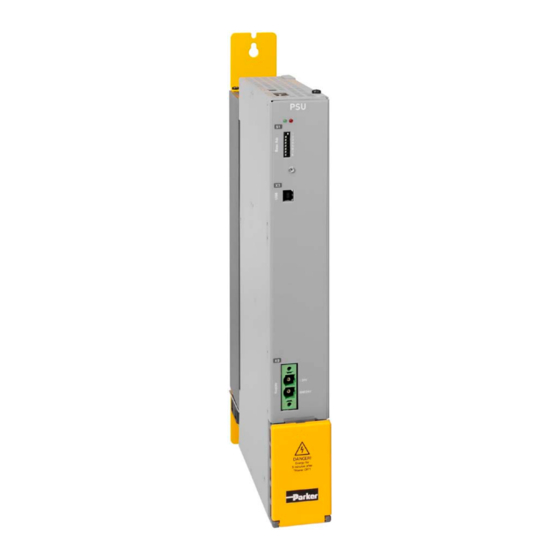
PSUP Mains module
Installation manual PSUP
Mains modules
We reserve the right to make technical changes.
The data correspond to the current status at the time of printing.
Electromechanical Automation
PSU-Manual-Set
Installations-Handbuch PSUP deutsch
Installation Manual PSUP english
192-120147N9 PSUP Manual 2019-06
DOC-0006-01
DOC-0006-01
192-120147N9 PSUP Manual
2019-06
Advertisement
Table of Contents

Related Manuals for Parker PSUP Series


Summary of Contents for Parker PSUP Series
- Page 1 PSUP Mains module Electromechanical Automation Installation manual PSUP Mains modules DOC-0006-01 DOC-0006-01 PSU-Manual-Set Installations-Handbuch PSUP deutsch Installation Manual PSUP english 192-120147N9 PSUP Manual 2019-06 192-120147N9 PSUP Manual 2019-06 We reserve the right to make technical changes. The data correspond to the current status at the time of printing.
- Page 2 Management Board: Ellen Raahede Secher, Dr.-Ing. Hans-Jürgen Haas, Günter Schrank, Kees Veraart - Chairman of the board of directors: Hansgeorg Greuner Italy: Parker Hannifin Manufacturing Srl • SSD SBC • Electromechanical & Drives Division • Via Gounod, 1 I-20092 Cinisello Balsamo (MI), Italy Tel.: +39 (0)2 361081 •...
-
Page 3: Table Of Contents
Device assignment Parker EME Contents 1. Introduction ..................... 4 Device assignment .................. 4 Scope of delivery ..................5 Packaging, transport, storage ..............6 Safety instructions ................... 7 1.4.1. General hazards ....................7 1.4.2. Safety-conscious working ................7 1.4.3. Special safety instructions ................8 Warranty conditions ................ -
Page 4: Introduction
Introduction PSUP Mains module 1. Introduction In this chapter you can read about: Device assignment ......................4 Scope of delivery ....................... 5 Packaging, transport, storage .................... 6 Safety instructions ......................7 Warranty conditions ......................9 Conditions of utilization for CE-conform operation ............10 Conditions of utilization for UL approval PSUP .............. -
Page 5: Scope Of Delivery
Scope of delivery Parker EME Scope of delivery The following items are furnished with the device: Manuals Installation manual (German, English) Device accessories Device accessories for PSUP Matching plug for the PSUP connectors X9, X40, X41 ... -
Page 6: Packaging, Transport, Storage
Introduction PSUP Mains module Packaging, transport, storage Packaging material and transport Caution! The packaging material is inflammable, if it is disposed of improperly by burning, lethal fumes may develop. The packaging material must be kept and reused in the case of a return shipment. Improper or faulty packaging may lead to transport damages. -
Page 7: Safety Instructions
Safety instructions Parker EME Safety instructions In this chapter you can read about: General hazards ........................ 7 Safety-conscious working ....................7 Special safety instructions ....................8 1.4.1. General hazards General Hazards on Non-Compliance with the Safety Instructions The device described in this manual is designed in accordance with the latest technology and is safe in operation. -
Page 8: Special Safety Instructions
Introduction PSUP Mains module 1.4.3. Special safety instructions Caution! Due to movable machine parts and high voltages, the device can pose a lethal danger. Danger of electric shock in the case of non-respect of the following instructions. The device corresponds to DIN EN 61800-3, i.e. it is subject to limited sale. -
Page 9: Warranty Conditions
Warranty conditions Parker EME Protective seals Caution! The user is responsible for protective covers and/or additional safety measures in order to prevent damages to persons and electric accidents. Please note in the event of Forming the capacitors storage >1 year:... -
Page 10: Conditions Of Utilization For Ce-Conform Operation
Do not place mains filter output cable parallel to the load cable. Accessories: Make sure to use only the accessories recommended by Parker Connect all cable shields at both ends, ensuring large contact areas! Warning: This is a product in the restricted sales distribution class according to EN 61800-3. -
Page 11: Conditions Of Utilization For Ul Approval Psup
Conditions of utilization for UL approval PSUP Parker EME Conditions of utilization for UL approval PSUP UL approval for mains modules PSUP Conform to UL: in accordance with UL508C Certified E-File_No.: E142140 The UL approval is documented by a “UL”... -
Page 12: Current On The Mains Pe (Leakage Current)
Introduction PSUP Mains module Current on the mains PE (leakage current) This product can cause a direct current in the protective lead. If a residual current device (RCD) is used for protection in the event of direct or indirect contact, only a type B (all current sensitive) RCD is permitted on the current supply side of this product . -
Page 13: Ec Declaration Of Conformity Psup
EC declaration of conformity PSUP Parker EME 1.10 EC declaration of conformity PSUP 192-120147N9 PSUP Manual 2019-06... -
Page 14: Device Description
Device description PSUP Mains module 2. Device description In this chapter you can read about: Meaning of the status LEDs - PSUP (mains module) ............14 Mounting and dimensions ....................15 PSUP Connections ......................17 Communication interfaces ....................24 Meaning of the status LEDs - PSUP (mains module) PSUP Status LEDs Left LED (green) Right LED (red) -
Page 15: Mounting And Dimensions
Mounting and dimensions Parker EME Mounting and dimensions Ventilation: During operation, the device radiates heat (power loss). Please provide for a sufficient mounting distance below and above the device in order to ensure free circulation of the cooling air. Please do also respect the recommended distances of other devices. -
Page 16: Mounting And Dimensions Psup20/Psup30
Device description PSUP Mains module 2.2.2. Mounting and dimensions PSUP20/PSUP30 Information on PSUP20/PSUP30 Mounting: 4 socket head screws M5 101mm 50,5mm 50,5mm 263mm 90° 400mm 360mm 100mm 96mm Tolerances: DIN ISO 2768-f 192-120147N9 PSUP Manual 2019-06... -
Page 17: Psup Connections
PSUP Connections Parker EME PSUP Connections In this chapter you can read about: Front connector ....................... 17 Connections on the device bottom ................... 18 Connections of the axis combination................19 Control voltage 24VDC PSUP (mains module) ..............20 Mains supply PSUP (mains module) X41................. 20 Braking resistor / temperature switch PSUP (mains module) ........... -
Page 18: Connections On The Device Bottom
Device description PSUP Mains module 2.3.2. Connections on the device bottom Caution - Risk of Electric Shock! Always switch devices off before wiring them! Dangerous voltages are still present until 10 min. after switching off the power supply. Caution! When the control voltage is missing there is no indication whether or not high voltage supply is available. -
Page 19: Connections Of The Axis Combination
PSUP Connections Parker EME 2.3.3. Connections of the axis combination The axis controllers are connected to the supply voltages via rails. Supply voltage 24VDC DC power voltage supply The rails can be found behind the yellow protective covers. In order to connect the rails of the devices, you may have to remove the yellow plastic device inserted at the side. -
Page 20: Control Voltage 24Vdc Psup (Mains Module)
Device description PSUP Mains module Reference value for the required capacity in an axis system 100 µF per kW of the temporal medium value of the total power (transmissions + power dissipation) in the axis system. Example: PSUP20 (1175 µF) with one axis controller (440 µF) Total power 15 kW, 100 µF/kW =>... - Page 21 PSUP Connections Parker EME Mains connection PSUP10D6 Device type PSUP10 230V 400V 480V 230VAC ±10% 400VAC ±10% 480VAC ±10% Supply voltage 50-60Hz 50-60Hz 50-60Hz Rated voltage 3AC 230V 3AC 400V 3AC 480V Input current 22Arms 22Arms 18Arms Output Voltage 325VDC ±10% 565VDC ±10%...
- Page 22 Device description PSUP Mains module Dimensional drawing: LCG-0055-0.45 mH Dimensional drawing: LCG-0055-0.45 mH-UL Caution - Risk of Electric Shock! Always switch devices off before wiring them! Dangerous voltages are still present until 10 min. after switching off the power supply. LCG-0055-0.45 Mains filter dimensions 2.3.5.1 Dimensional drawing: LCG-0055-0.45 mH...
-
Page 23: Braking Resistor / Temperature Switch Psup (Mains Module)
PSUP Connections Parker EME Dimensional drawing: LCG-0055-0.45 mH-UL 2.3.6. Braking resistor / temperature switch PSUP (mains module) The energy generated during braking operation must be dissipated via a braking resistor. Connector X40 Description + Braking resistor short-circuit proof! - Braking resistor... -
Page 24: Communication Interfaces
Device description PSUP Mains module Temperature switch PSUP (mains module) 2.3.6.1 Connector X40 Pin T1R, T2R Temperature monitoring: The temperature switch (normally closed contact) must be connected, unless an error message will be issued. Temperature switch/relay No galvanic separation, the temperature sensor (normally closed contact) must comply with the safe separation according to EN 60664. -
Page 25: Technical Characteristics
Communication interfaces Parker EME 3. Technical Characteristics Size / weight PSUP Dimensions HxWxD Weight Device type [mm] [kg] PSUP10D6 360 x 50 x 263 3.95 PSUP20D6 & PSUP30D6 360 x 100 x 263 Protection type IP20 Mains connection PSUP10D6 Device type PSUP10... - Page 26 Technical Characteristics PSUP Mains module PSUP30D6 Mains connection Device type PSUP30 230V 400V 480V Supply voltage 230VAC ±10% 400VAC ±10% 480VAC ±10% 50-60Hz 50-60Hz 50-60Hz Rated voltage 3AC 230V 3AC 400V 3AC 480V Input current 50Arms 50Arms 42Arms Output Voltage 325VDC ±10% 565VDC ±10% 680VDC ±10%...
- Page 27 Communication interfaces Parker EME Ambient conditions PSUP General ambient conditions In accordance with EN 60 721-3-1 to 3-3 Climate (temperature/humidity/barometric pressure): Class 3K3 Permissible ambient temperature: Operation 0 to +40 °C Class 3K3 storage -25 to +70 °C transport -25 to +70 °C...
-
Page 28: Index
Index PSUP Mains module 4. Index Safety-conscious working • 7 Scope of delivery • 5 Special safety instructions • 8 Adjusting the basic address • 24 Status LEDs • 14 Storage • 6 Supply networks • 12 Braking resistor / temperature switch PSUP (mains module) •...
Need help?
Do you have a question about the PSUP Series and is the answer not in the manual?
Questions and answers