Table of Contents
Advertisement
Quick Links
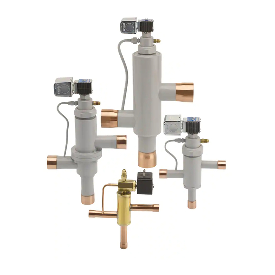
3-Way Valves
Installation AND SERVICING INSTRUCTIONS
SD-114 / 122013
GENERAL INFORMATION
Installation Precautions
1. Do not attempt installation of the valve before
pumping the entire system down. Make abso-
lutely certain system pressure is no more than 2
or 3 psi above atmospheric pressure.
2. The solenoid coil must not be energized unless it
is installed on the valve. To do so would cause
coil to overheat and burn out.
3. The solenoid coil should be fused in accordance
with local codes.
4. If a service valve is installed ahead of a solenoid
valve, it should be closed during service proce-
dures. Do not use a solenoid valve as a safety
shutoff while making repairs to the system.
Be sure there is no liquid in the line between
the service and solenoid valves when they
are in the closed position that could create
dangerous hydraulic pressures.
5. Do not twist the valve assembly by pulling or
pushing on the enclosing tube or coil assembly.
6. Do not carry a coil assembly or complete valve
by the coil leads. This could damage the coil and
cause a coil burnout. Do not carry the valve by
the pilot tube. This could cause damage to the
flare (SAE) joint, creating an external leak.
7. Electrically ground the valve body. Typically
this is done through the fluid piping or the elec-
trical conduit.
8. Before energizing the valve, verify that the sup-
ply voltage and frequency matches the solenoid
coil marking.
Soldering Precautions
Solder connections on Sporlan Heat Reclaim Valves
are copper. Any of the commonly used types of sol-
der are satisfactory with these materials. Regardless
of the type of solder used, it is important to avoid
over-heating the valve. Extreme care should be
taken when brazing connections to avoid dam-
age to internal synthetic parts. The torch tip
should be large enough to avoid prolonged heating
of the connection during the brazing operation.
Overheating can also be minimized by directing
the flame away from the valve body. As an extra
precaution, a wet cloth may be wrapped around the
body. Cool body thoroughly after making each
connection. As an extra precaution, a wet cloth
may be wrapped around the body during the
soldering operation.
CAUTION: When installing 1/4" flare pilot line
connections, flare body MUST be supported with
another wrench. On the B5D valve, the pilot valve
body MUST be supported when tightening the 1/4"
flare connection. Failure to do either of the above
may cause leaks or valve damage.
Wiring
Check the electrical specifications of the coil to be
sure that they correspond to the available electrical
Service. See page 4 for typical wiring schematics for
single compressor systems.
The 1/2" BX conduit connection of junction box
on the coil of Heat Reclaim Valves may be rotated
to any position by loosening the coil screw. Valves
with four-wire dual voltage coil have a wiring dia-
gram decal (see diagram below) on the coil housing
or bracket. This illustrates which wires to connect
for either 120, 208, or 240 volt operation. Wiring
and fusing (when used) must comply with prevail-
ing local and national wiring codes and ordinanc es.
BLUE
YELLOW
RED
BLACK
120-V
Transformer Selection
Temperature Ratings
Replacement Part Kits for (S)8D, (S)12D, (S)16D,
(S)8D-SC, (S)12D-SC, (S)16D-SC, 10G
The parts kit for the 3-Way Heat Reclaim Valves
includes the piston assembly. The Bleed "B" and
Non-Bleed "C" versions of the 3-Way valves use
different pistons; therefore, different parts kits are
required.
BLUE
BLACK
RED
YELLOW
208-V
240-V
Advertisement
Table of Contents

Related Manuals for Parker Sporlan SD-114


Summary of Contents for Parker Sporlan SD-114
- Page 1 3-Way Valves INSTALLATION AND SERVICING INSTRUCTIONS SD-114 / 122013 GENERAL INFORMATION body. Cool body thoroughly after making each connection. As an extra precaution, a wet cloth may be wrapped around the body during the Installation Precautions soldering operation. 1. Do not attempt installation of the valve before pumping the entire system down.
- Page 2 CAUTION: If you are replacing the internal parts The parts kits contain gaskets for both of two dif- on an older “B” style valve with split piston rings, ferent pilot valve designs shown at the left. Use only you must use the existing piston and piston rings. the gasket that matches the design, as shown.
- Page 3 Recommended Torque Enclosing Tube Pilot Valve Lower Body Body Flange Valve Series Coil Screw Locknut Assembly Locknut Locknut Cap Screw S8D, S8D-HP, 8D, 8D-SC, — 10-15 60-65 8D-HP, S8D-SC S12D, S12D-HP, — 15-18 10-15 60-65 12D, 12D-SC, S12D-SC — 20-24 16D, 16D-SC 30-35 S16D, S16D-SC, 16D,...
- Page 4 Head Pressure Control for Reclaim 3. Failure to shift to Normal Mode. Each typical malfunction is discussed below: Systems When employing heat reclaim on a refrigeration COIL BURNOUT system, the addition of head pressure controls is Coil burnouts are extremely rare unless caused by important not only to maintain liquid pressure at one of the following: the expansion valve inlet, but also to assure the...
- Page 5 FAILURE TO SHIFT TO RECLAIM MODE 1. Coil burnout (see Coil Burnout section on page 4). Figure 3 2. MOPD greater than specifications. 3. Restricted high pressure pilot connection. Suction 4. May not have allowed sufficient time to pump Pilot Valve out the reclaim coil while in the normal mode.
- Page 6 ELECTRICAL For normal summer operation of air conditioning 49 LBS. Bulb Pressure systems, the Type 180 Solenoid Pilot Control may be energized through any actuating device such as 120 LBS. a thermostat, a micro-switch, or a manual switch. Head The compressor can be operated separately through Pressure Spring Pressure...
- Page 7 3. Check to ascertain that the low pressure port 7. Inspect the piston T and seat assembly { for is closing tightly. A leak in many instances damage. Replace all tetraseals or gaskets E O if can be detected by a much cooler line from valve has been in service.
- Page 8 OFFER OF SALE The items described in this document are hereby offered for sale by Parker Hannifin Corporation, its subsidiaries or its authorized distributors. This offer and its acceptance are governed by the provisions stated in the detailed “Offer of Sale” available at www.parker.com.
Need help?
Do you have a question about the Sporlan SD-114 and is the answer not in the manual?
Questions and answers