Table of Contents
Advertisement
Quick Links
Advertisement
Table of Contents

Related Manuals for FLIR DM93


Summary of Contents for FLIR DM93
- Page 1 User’s manual FLIR DM93 True RMS Industrial Multimeter...
-
Page 3: Table Of Contents
Table of contents Disclaimers............. . 1 Copyright. - Page 4 Table of contents 5.11.4 Min/Max/Avg mode ....... .21 5.11.5 Frequency mode (ACV and ACA only) ... .22 5.11.6 Relative mode .
-
Page 5: Disclaimers
WEEE will be collected di- FLIR Systems is committed to a policy of continuous de- rectly from households. More detailed information is avail- velopment; therefore we reserve the right to make... -
Page 6: Safety Information
Note Before operating the device, you must read, understand, and follow all in- structions, dangers, warnings, cautions, and notes. Note FLIR Systems reserves the right to discontinue models, parts or accesso- ries, and other items, or to change specifications at any time without prior notice. - Page 7 2 Safety information WARNING You must disconnect the test leads from the circuit that you did a test on be- fore you change the range. If you do not do this, damage to the instrument and injury to persons can occur. WARNING Do not replace the batteries or the fuses before you remove the test leads.
- Page 8 2 Safety information WARNING Only use this equipment indoors. This instrument is not for permanent outdoor installations. Damage to the equipment can occur if you use it outdoors. WARNING Do not apply a voltage to the unit when: • It is not in the specified range •...
-
Page 9: Fcc Compliance
2 Safety information This symbol, adjacent to another symbol or terminal, indicates that the user must refer to the manual for further information. This symbol, adjacent to a terminal, indicates that, under normal use, hazardous voltages may be present. Double insulation. UL listing is not an indication or a verification of the accuracy of the meter 2.1 FCC Compliance... -
Page 10: Industry Canada Compliance
2 Safety information CAUTION Exposure to Radio Frequency Radiation. To comply with FCC/IC RF exposure compliance requirements, a separation distance of at least 20 cm must be maintained between the antenna of this de- vice and all persons. This device must not be co-located or operating in con- junction with any other antenna or transmitter. -
Page 11: Introduction
3 Introduction Thank you for choosing a FLIR DM93 digital multimeter. This device is shipped fully tested and calibrated and, with proper use, will pro- vide years of reliable service. 3.1 Key features • 4000/40 000 counts extra-large digital dual display. -
Page 12: Description
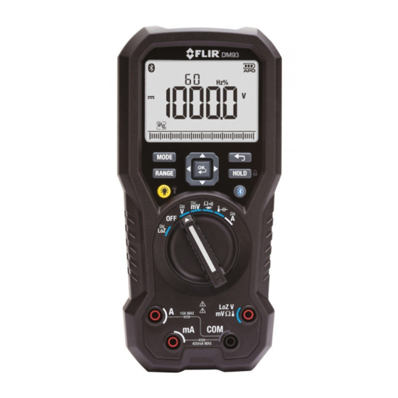
4 Description 4.1 Meter description Figure 4.1 Front view LCD display. Function buttons, see section 4.3 Function buttons, page 10. Selector pad. Function switch, see section 4.2 Function switch, page 9. Probe input terminals. #T559824; r. AN/86262/86262; en-US... -
Page 13: Function Switch
4 Description Figure 4.2 Rear view Probe clips. Tilt stand. Work light. Battery compartment cover. 4.2 Function switch The meter can measure voltage through the probe inputs. A low- impedance load is placed across the inputs to stabilize the measurement. The meter is in full power-saving mode. -
Page 14: Function Buttons
4 Description The meter can measure resistance, continuity, or diode polarity through the probe inputs. The type of measurement is selected by button. The meter can measure capacitance through the probe inputs or temperature through a thermocouple adapter. The type of meas- urement is selected by the button. -
Page 15: Display Description
4 Description • Press the button to enable/disable the display backlight. • Press and hold the button for 2 seconds to enable/disable the work light. Press the button to enable/disable METERLiNK® (Bluetooth) communication, see section 5.14 Streaming measurement data using Bluetooth, page 27. 4.4 Display description Secondary display. - Page 16 4 Description Indicates that the meter is displaying peak minimum values. Indicates that the meter is in Auto range mode. Indicates that the meter is in Hold mode. Indicates that the meter is in Locked mode. Indicates the active memory location (1–99). Indicates the battery voltage status.
-
Page 17: Probe Indicator
4 Description 20,000 point Automatic Data Recording (Sampling) mode icon. Setup mode icon. Silent mode icon. 4.5.1 Probe indicator When the probe leads are not plugged into the correct jack sockets for the meas- urement selected by the function switch, PROBE is displayed. 4.5.2 Out-of-range warning If the input is over/under the full-scale range in Manual range mode, or if the sig- nal has exceeded the maximum/minimum input in Auto range mode, OL is... -
Page 18: Operation
5 Operation Note Before operating the device, you must read, understand, and follow all in- structions, dangers, warnings, cautions, and notes. NOTE When the meter is not in use, the function switch should be set to the position. NOTE When connecting the probe leads to the device under test, connect the nega- tive lead before connecting the positive lead. -
Page 19: Auto/Manual Range Mode
NOTE Note that the DM93 Data Recording feature cannot be used when the meter is in the Auto Select Mode. To use the Data Recorder please set the meter to the Manual Select mode first. 5.3 Auto/Manual Range mode In Auto Range mode, the meter automatically selects the most appropriate meas- urement scale. -
Page 20: Voltage Measurements
5 Operation 5.4 Voltage measurements Set the function switch to one of the following positions: • for high voltage measurements. • for low voltage measurements. • for voltage measurements using the meter's low input impedance mode. The indicator is displayed. Insert the black probe lead into the negative terminal and the red probe lead into the positive... -
Page 21: Continuity Test
5 Operation 5.6 Continuity test WARNING Do not do diode, resistance, or continuity tests before you remove the power from the capacitors and the other devices (when you do a test during a meas- urement). Injury to persons can occur. Set the function switch to the position. -
Page 22: Capacitance Measurements
5 Operation Figure 5.1 Diode testing Set the function switch to the diode position. Insert the black probe lead into the negative terminal and the red probe lead into the positive terminal. Use the button to select the diode test function. The diode indica- tor will be displayed. -
Page 23: Type K Temperature Measurements
5 Operation Read the capacitance value on the display. NOTE For very large capacitance values, it may take several minutes for the measurement to settle and the final reading to stabilize. 5.9 Type K temperature measurements Set the function switch to the position. -
Page 24: Extended Functionality
5 Operation Insert the black probe lead into the negative terminal and the red probe lead into one of the following positive terminals: • for high current measurements. • for low current measurements. Use the button to select AC, DC, or AC+DC voltage measurement. •... -
Page 25: Vfd Mode (Acv And Aca Only)
5 Operation 5.11.2 VFD mode (ACV and ACA only) In VFD (variable-frequency drive) mode, high-frequency noise is eliminated from the voltage measurement by a low-pass filter. VFD mode is available when meas- uring AC voltage or AC current. Select and enable VFD mode as described in section 5.11.1 Selecting the mode, page 20. -
Page 26: Frequency Mode (Acv And Aca Only)
5 Operation 5.11.5 Frequency mode (ACV and ACA only) In Frequency mode, the frequency is displayed in the main display and the period is displayed in the secondary display. Frequency mode is available when measur- ing AC voltage or current. Select and enable Frequency mode as described in section 5.11.1 Se- lecting the mode, page 20. -
Page 27: Automatic Data Recording Mode
5 Operation Press the button to activate the displayed option: • SAVE: The data on the main display is saved to the memory location shown by the indicator in the upper part of the display. • LOAD: The data stored in the memory location shown by the indica- tor is displayed. - Page 28 SAVE. The data will start downloading to the FLIR Tools application and a message will appear in FLIR Tools: “Waiting for log file to be received from Flir DM93…”. The DM93 meter will show a number representing the download progress as a percentage. When the meter reaches 100%, the data will be visible in FLIR Tools under LIBRARY.
-
Page 29: Setup Mode
5 Operation 5.11.10 Setup mode In Setup mode, you can define the settings for various meter options: • Auto power off (indicated by the text APO): A mode where the time period after which the meter enters sleep mode can be set. The range is 1 to 30 mi- nutes, or Off. -
Page 30: Normal Hold Mode And Auto Hold Mode
5 Operation 5.12 Normal hold mode and Auto hold mode The meter has two types of hold modes: • Normal hold mode. • Auto hold mode. 5.12.1 Normal hold mode In Normal hold mode, the meter freezes and displays the last reading from the main display and continues to display this value. -
Page 31: Streaming Measurement Data Using Bluetooth
5.14 Streaming measurement data using Bluetooth 5.14.1 General Some IR cameras from FLIR Systems support Bluetooth communication, and to those cameras you can stream measurement data from the meter. The data is then merged into the result table in the IR image. -
Page 32: Maintenance
6 Maintenance 6.1 Cleaning and storage Clean the meter with a damp cloth and mild detergent; do not use abrasives or solvents. If the meter is not to be used for an extended period, remove the batteries and store them separately. 6.2 Battery replacement To avoid electrical shock, disconnect the meter if connected to a circuit, re- move the probe/thermocouple leads from the terminals, and set the function... - Page 33 6 Maintenance #T559824; r. AN/86262/86262; en-US...
-
Page 34: Technical Specifications
7 Technical specifications 7.1 General specifications Maximum voltage applied to any terminal: 1000 V DC or 1000 V AC RMS. Display count: 4000/40 000. Polarity indication: Automatic, positive implied, negative indicated. Over-range indication: OL. Measuring rate: 10 samples per second. Power requirements: 6 ×... -
Page 35: Electrical Specifications
7 Technical specifications Application field Circuits not connected to mains Circuits directly connected to a low- voltage installation Building installation Source of the low-voltage installation EMC: EN 61326-1. Altitude: 2000 m (6561 ft.). Pollution degree: 2. Shock vibration: Per MIL-PRF-28800 for a Class 2 instrument. Drop protection: 3 m (9.8 ft.). - Page 36 7 Technical specifications Table 7.1 Voltage. Resolution of specifications in the 3 ¾-digit mode. Mode Range Accuracy 40.00 mV 0.05%+3d 400.0 mV 4.000 V 40.00 V 0.05%+1d 400.0 V 1000 V 40 Hz to 70 Hz to 1 kHz to 5 kHz to 70 Hz 5k Hz...
- Page 37 7 Technical specifications • V AC: CMRR > 60 dB at DC, 50 Hz/60 Hz. • V DC: CMRR > 100 dB at DC, 50 Hz/60 Hz. • NMRR > 50 dB at DC, 50 Hz/60 Hz. AC conversion type: AC coupled, true RMS responding, calibrated to the sine wave input.
- Page 38 7 Technical specifications Minimum resolution: 1 µA in the 40 mA range. Maximum measuring time: 1 minute at A input, 10 minutes at mA input. Rest time is 20 minutes minimum. AC conversion type: The AC conversion type is the same as for the voltage. Table 7.3 AC additional specifications Mode Range...
- Page 39 7 Technical specifications Table 7.5 Frequency counter sensitivity Function Range Sensitivity Sensitivity (peak to peak) (peak to peak) 5 Hz to 10 kHz 10–100 kHz 40.00 mV 10 mV 10 mV 400.0 mV 100 mV 100 mV 4.000 V 40.00 V 10 V 10 V 400.0 V...
- Page 40 7 Technical specifications Table 7.7 Continuity check. Resolution of specifications in the 3 ¾-digit mode. Range Resolution Accuracy 400.0 Ω 100 mΩ ±(0.2% + 2 dgt) Input protection: 1000 V DC or 1000 V AC RMS. Maximum open circuit voltage: Approx. 2.5 V. Maximum short test current: Approx.
- Page 41 7 Technical specifications Input protection: 1000 V DC or 1000 V AC RMS. Table 7.10 Temperature Range Resolution Accuracy –328℉ to 2192℉ 0.1℉ 1.0% + 36d –200℃ to 1200℃ 0.1℃ 1.0% + 20d Input protection: 1000 V DC or 1000 V AC RMS. NOTE Accuracy specification assumes the ambient temperature is stable to ±1℃...
-
Page 42: Technical Support For External Meters
8 Technical support for external meters Repair, Calibration, and Technical https://support.flir.com Support #T559824; r. AN/86262/86262; en-US... -
Page 43: Warranty
9 Warranty This product is protected by FLIR’s Limited Lifetime Warranty. Visit www.flir.com/testwarranty to read the Limited Lifetime Warranty document. Register your product at the website. #T559824; r. AN/86262/86262; en-US... - Page 44 A note on the technical production of this publication This publication was produced using XML — the eXtensible Markup Language. For more information about XML, please visit http://www.w3.org/XML/ A note on the typeface used in this publication This publication was typeset using Linotype Helvetica™ World. Helvetica™ was designed by Max Miedinger (1910–1980) LOEF (List Of Effective Files) T501024.xml;...
- Page 45 Customer support http://support.flir.com Copyright © 2022, FLIR Systems, Inc. All rights reserved worldwide. Disclaimer Specifications subject to change without further notice. Models and accessories subject to regional market considerations. License procedures may apply. Products described herein may be subject to US Export Regulations. Please refer to exportquestions@flir.com with any questions.
Need help?
Do you have a question about the DM93 and is the answer not in the manual?
Questions and answers