Table of Contents
Advertisement
Quick Links
Advertisement
Table of Contents

Related Manuals for FLIR DM91


Summary of Contents for FLIR DM91
- Page 1 USER MANUAL FLIR MODEL DM91 True RMS Industrial Multimeter with Bluetooth®...
-
Page 2: Table Of Contents
5.2 Auto/Manual Range Mode 5.3 Voltage and Frequency Measurements 5.4 Resistance Measurements 5.5 Continuity Test 5.6 Classic Diode Test 5.7 Smart Diode Test 5.8 Capacitance Measurements 5.9 Type K Temperature Measurements 5.10 Current and Frequency Measurements FLIR DM91 USER MANUAL Document Identifier: DM91-en-US_AB... - Page 3 6.7 Datalogger 6.8 Settings Menu 6.9 Data Hold and Auto Hold 6.9.1 Data Hold Mode 6.9.2 Auto Hold Mode 7. BLUETOOTH® COMMUNICATION AND FLIR TOOLS 8. MAINTENANCE 8.1 Cleaning and Storage 8.2 Battery Replacement 8.3 Fuse Replacement 8.4 Disposal of Electronic Waste 9.
-
Page 4: Advisories
1. Advisories 1.1 Copyright © 2019, FLIR Systems, Inc. All rights reserved worldwide. No parts of the software including source code may be reproduced, transmitted, transcribed or translated into any language or computer language in any form or by any means, electronic, magnetic, optical, manual or otherwise, without the prior written permission of FLIR Systems. -
Page 5: Safety
Before operating the device, you must read, understand, and follow all instructions, dangers, warnings, cautions, and notes. • FLIR Systems reserves the right to discontinue models, parts or accessories, and other items, or to change specifications at any time without prior notice. •... - Page 6 This symbol, adjacent to a terminal, indicates that, under normal use, hazardous voltages may be present. Double insulation. UL listing is not an indication or a verification of the accuracy of the meter FLIR DM91 USER MANUAL Document Identifier: DM91-en-US_AB...
-
Page 7: Introduction
3. Introduction Thank you for selecting the FLIR DM91 True RMS Digital MultiMeter with Bluetooth®, Type-K thermocouple, automatic datalogging, and work light features. The DM91 can measure voltage up to 1000V AC/DC and includes Low-Z (low impedance), VFD (low pass filter), Non-Contact Voltage Detector, and Smart/Classic Diode modes. This device is shipped fully tested and calibrated and, with proper use, will provide years of reliable service. -
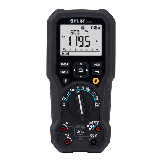
Page 8: Meter Description
13. Cancel/Return Button 14. Display HOLD Button 1. Test Lead holder attachment mounts 2. Tripod mount (test lead holder attaches here also) 3. Tilt Stand (Battery Compartment located beneath the stand) Fig. 4-2 Rear View FLIR DM91 USER MANUAL Document Identifier: DM91-en-US_AB... -
Page 9: Function Switch Positions
Measure µA current through the probe inputs. Use the MODE button to select AC or DC. Measure current through the probe inputs (A or mA). Use the MODE button to select AC or DC. Fig. 4-3 Function Switch FLIR DM91 USER MANUAL Document Identifier: DM91-en-US_AB... -
Page 10: Function Buttons And Selector/Navigation Pad
Press to switch the work light ON or OFF. 4.3.1 MODE Button Operation Switch Position MODE button sequence of operation AC → DC → °F or °C Resistance → Continuity → Capacitance → Diode AC → DC AC → DC FLIR DM91 USER MANUAL Document Identifier: DM91-en-US_AB... -
Page 11: Selector/Navigation Pad Operation
The UP/DOWN buttons: In normal mode, the up/down buttons have no function In Settings mode, the up/down buttons change an option. 4.4 Display Description Fig. 4-5 Display Icons (see Section 4-5 for descriptions) FLIR DM91 USER MANUAL Document Identifier: DM91-en-US_AB... -
Page 12: Display Icons And Indicators
Bluetooth® active icon (see Section 7, Bluetooth® Communication) Auto power off function enabled Battery voltage status Flex Clamp Direct Input Primary display (large digits) with units of measure MENU BAR ICON: Settings mode FLIR DM91 USER MANUAL Document Identifier: DM91-en-US_AB... -
Page 13: Probe Detection Alert
‘Prob’ is shown. 4.5.2 Out-of-range warning If the input is over/under the full-scale range in Manual range mode, or if the signal has exceeded the maximum/minimum input in Auto range mode, ‘OL’ is displayed. FLIR DM91 USER MANUAL Document Identifier: DM91-en-US_AB... -
Page 14: Mode Menu Bar Basics
(the exception is that the Hz function is not available in the mode). 5. For DC Current/Voltage, Resistance, Continuity, Capacitance, Temperature, and Diode only the MAX-MIN-AVG, Relative, Datalogger, and Settings icons are available. FLIR DM91 USER MANUAL Document Identifier: DM91-en-US_AB... -
Page 15: Operation
To change the range, press the button repeatedly until the desired range appears. 2. To return to the Auto range mode, long press the button until the Auto Range indicator again appears. FLIR DM91 USER MANUAL Document Identifier: DM91-en-US_AB... -
Page 16: Voltage And Frequency Measurements
To display only the Frequency, navigate to the menu icon using the arrow buttons and enable (or disable) the mode by pressing OK. Fig. 5-1 Voltage and Frequency Measurements FLIR DM91 USER MANUAL Document Identifier: DM91-en-US_AB... -
Page 17: Resistance Measurements
5. If the resistance is < 20Ω the meter beeps. If the resistance is > 200Ω the meter will not beep. If the resistance is > 20Ω but < 200Ω the beeping will stop at an unspecified point. Fig. 5-2 Resistance and Continuity Measurements FLIR DM91 USER MANUAL Document Identifier: DM91-en-US_AB... -
Page 18: Classic Diode Test
5. If the reading is between 0.400 and 0.800V in one direction and OL (overload) in the opposite direction, the component is good. If the measurement is 0V in both directions (shorted) or OL in both directions (open), the component is bad. Fig. 5-3 Classic Diode Measurements FLIR DM91 USER MANUAL Document Identifier: DM91-en-US_AB... -
Page 19: Smart Diode Test
The meter display will show ± 0.400 ~ 0.800V for a good diode, ‘bAd’ for a shorted diode, and ‘O.L’ for an opened diode. See Fig. 5.4 below: Fig. 5-4 SMART Diode Test FLIR DM91 USER MANUAL Document Identifier: DM91-en-US_AB... -
Page 20: Capacitance Measurements
5. Read the capacitance value on the display. Note: For very large capacitance values, it may take several minutes for the measurement to settle and the final reading to stabilize. Fig. 5-5 Capacitance Measurements FLIR DM91 USER MANUAL Document Identifier: DM91-en-US_AB... -
Page 21: Type K Temperature Measurements
5. Read the temperature value on the display. 6. To avoid electrical shock, disconnect the thermocouple adapter before turning the function switch to another position. Fig. 5-6 Temperature Measurements FLIR DM91 USER MANUAL Document Identifier: DM91-en-US_AB... -
Page 22: Current And Frequency Measurements
5. Read the current and frequency values on the display (note that the frequency function is not available for the µA function). To display only the Frequency, navigate to the Hz icon and enable (or disable) the mode by pressing OK. FLIR DM91 USER MANUAL Document Identifier: DM91-en-US_AB... - Page 23 Fig. 5-8 High Current ‘A’ and Frequency Measurements Fig. 5-9 mA Current and Frequency Measurements FLIR DM91 USER MANUAL Document Identifier: DM91-en-US_AB...
- Page 24 Fig. 5-10 uA Current Measurements FLIR DM91 USER MANUAL Document Identifier: DM91-en-US_AB...
-
Page 25: Flex Clamp Adaptor Current Measurements
2. Connect a Clamp adaptor as shown in Fig. 5-11. 3. Set the Range of the Flex Clamp Adaptor to match the range of the DM91. 4. Use the button to select the range of the DM91 (1, 10, 100 mv/A). The selected range appears on the right side of the DM91 display. -
Page 26: Non-Contact Voltage Detector
4. Position the top of the meter close to a source of voltage or electromagnetic field. 5. When the meter detects a voltage or electromagnetic field, it will emit a continuous tone. Fig. 5-12 Non-Contact Voltage Detector FLIR DM91 USER MANUAL Document Identifier: DM91-en-US_AB... -
Page 27: Menu Bar For Extended Functionality
6. Menu Bar for Extended Functionality In addition to the basic measurement functions, the DM91 offers extended functionality as detailed below. 6.1 Selecting Modes using the Menu Bar The menu icons appear in the lower part of the display. When you enable a mode, a frame appears around the icon. -
Page 28: Frequency Mode (Acv And Aca Only)
(left) of the data log. Press the RETURN button to exit the VIEW mode. SEND: Pair the DM91 to a remote device running FLIR Tools via Bluetooth® (BLE). Set FLIR Tools to Measurements mode. On the DM91, at SEND, press the OK button. -
Page 29: Settings Menu
Use left/right arrows to set current day hour Use left/right arrows to set current hour Use left/right arrows to set current minute Press OK at the (yES) prompt to revert to factory default settings FLIR DM91 USER MANUAL Document Identifier: DM91-en-US_AB... -
Page 30: Data Hold And Auto Hold
Current > 1% full scale Capacitance > 1% full scale Resistance With ‘OL’ not displayed Diode With ‘OL’ not displayed Temperature With ‘OL’ not displayed To enter/exit Auto hold mode, press the button. FLIR DM91 USER MANUAL Document Identifier: DM91-en-US_AB... -
Page 31: Bluetooth® Communication And Flir Tools Tm
7. Bluetooth® Communication and FLIR Tools When connected to a mobile device running the FLIR Tools app, the DM91 (using the METERLiNK® protocol) can: • Send readings for live display on the mobile device • Send saved data log files to the mobile device... -
Page 32: Maintenance
OFF position before attempting to replace the batteries. 1. The DM91 is equipped with an easy-open battery compartment 2. Turn the compartment fastener to the unlocked position using a flat-head screwdriver. -
Page 33: Specifications
Circuits not connected to mains. Circuits directly connected to a low-voltage installation. Building installation. Source of the low-voltage installation. EMC: EN 61326-1 Pollution degree: 2 Drop protection: 9.8’ (3m) Max. Operating Altitude: 6562 ft (2000m) FLIR DM91 USER MANUAL Document Identifier: DM91-en-US_AB... -
Page 34: Electrical Range Specifications
Freq. Response 6.000V 6.600V 0.001V ±(1.0% + 3D) 45Hz ~ 500Hz 60.00V 66.00V 0.01V 600.0V 660.0V 0.1V ±(1.0% + 3D) 45Hz ~ 1kHz 1000V 1100V Input Impedance: 10MΩ (< 100pF) Overload Protection: AC/DC 1000V FLIR DM91 USER MANUAL Document Identifier: DM91-en-US_AB... - Page 35 Maximum measurement time: > 5A for max. 3 minutes with at least 20-minute rest time. > 10A for max.30 seconds with at least 10-minute rest time. Overload Protection: AC/DC 11A for A terminal. AC/DC 660mA for mA terminal. FLIR DM91 USER MANUAL Document Identifier: DM91-en-US_AB...
- Page 36 6.600kΩ 0.001kΩ ±(0.9% + 2D) 60.00kΩ 66.00kΩ 0.01kΩ ±(0.9% + 2D) 600.0kΩ 660.0kΩ 0.1kΩ ±(0.9% + 2D) 6.000MΩ 6.600MΩ 0.001MΩ ±(0.9% + 2D) 50.00MΩ 55.00MΩ 0.01MΩ ±(3.0% + 5D) Overload Protection: AC/DC 1000V FLIR DM91 USER MANUAL Document Identifier: DM91-en-US_AB...
- Page 37 100mV Unspecified 6.000V 0.6V Unspecified 60.00V Unspecified 600.0V 100V Unspecified 1000V 600V Unspecified Unspecified ACA - Minimum Sensitivity: Range 5Hz ~ 10kHz >10kHz 60.00mA 10mA Unspecified 600.0mA 60mA Unspecified 6.000A Unspecified 10.00A Unspecified FLIR DM91 USER MANUAL Document Identifier: DM91-en-US_AB...
- Page 38 Accuracy specification assumes surrounding temperature stable to ±1 °C. For surrounding temperature changes of ± 2 °C, rated accuracy applies after 2 hours. Accuracy specified for use with work light and backlight off only. Overload Protection: AC/DC 1000V. FLIR DM91 USER MANUAL Document Identifier: DM91-en-US_AB...
-
Page 39: Technical Support
For ACV, AC mV, ACA, ACmA, AC μA, and Flex Current modes (unavailable for LoZ mode) Specified accuracy is for 45Hz ~ 65Hz Specified accuracy ± 4% for 65Hz ~ 400Hz Accuracy is unspecified for > 400Hz Cut-off Frequency: 800Hz 10. Technical Support Technical Support Website https://support.flir.com FLIR DM91 USER MANUAL Document Identifier: DM91-en-US_AB... -
Page 40: Warranty
11. Warranty 11.1 FLIR Global Limited Lifetime Warranty This product is protected by FLIR’s Limited Lifetime Warranty. Visit https://support.flir.com/prodreg to read the Limited Lifetime Warranty document. FLIR DM91 USER MANUAL Document Identifier: DM91-en-US_AB... - Page 41 Corporate Headquarters FLIR Systems, Inc. 27700 SW Parkway Avenue Wilsonville, OR 97070 www.flir.com Technical Support Website: https://support.flir.com Publication Identification No.: DM91-en-US Release Version: Release Date: December 2019 Language: en-US FLIR DM91 USER MANUAL Document Identifier: DM91-en-US_AB...
Need help?
Do you have a question about the DM91 and is the answer not in the manual?
Questions and answers