Table of Contents
Advertisement
Quick Links
Download this manual
See also:
User Manual
Advertisement
Table of Contents

Related Manuals for FLIR DM93


Summary of Contents for FLIR DM93
- Page 1 User’s manual Flir DM93 Digital multimeter...
- Page 3 User’s manual Flir DM93 #T559824; r.8007/8011; en-US...
-
Page 5: Table Of Contents
Table of contents Disclaimers............. . 1 Copyright. - Page 6 Input specifications ......... . .29 Flir Global Limited Lifetime Warranty .......30...
-
Page 7: Disclaimers
ISO 9001 standard. Flir Systems is committed to a policy of continuous devel- opment; therefore we reserve the right to make changes and improvements on any of the products without prior notice. -
Page 8: Safety Information
Before operating the device, you must read, understand, and follow all in- structions, dangers, warnings, cautions, and notes. Note Flir Systems reserves the right to discontinue models, parts or accessories, and other items, or to change specifications at any time without prior notice. Note Remove the batteries if the device is not used for an extended period of time. - Page 9 2 Safety information WARNING Do not measure the current on a circuit when the voltage increases to more than 600 V. This can cause damage to the instrument and can cause injury to persons. WARNING You must disconnect the test leads from the circuit that you did a test on be- fore you change the range.
- Page 10 2 Safety information WARNING Do not use the device as a tool to identify live terminals. You must use the cor- rect tools. Injury to persons can occur if you do not use the correct tools. WARNING Make sure that children cannot touch the device. The device contains danger- ous objects and small parts that children can swallow.
- Page 11 2 Safety information This symbol, adjacent to another symbol or terminal, indicates that the user must refer to the manual for further information. This symbol, adjacent to a terminal, indicates that, under normal use, hazardous voltages may be present. Double insulation. #T559824;...
-
Page 12: Introduction
3 Introduction Thank you for choosing a Flir DM93 digital multimeter. This device is shipped fully tested and calibrated and, with proper use, will pro- vide years of reliable service. 3.1 Key features • 40 000/4000-count extra-large digital display. •... -
Page 13: Description
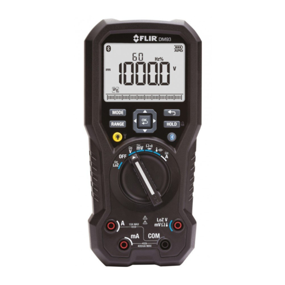
4 Description 4.1 Meter description Figure 4.1 Front view LCD display. Function buttons, see section 4.3 Function buttons, page 9. Selector pad. Function switch, see section 4.2 Function switch, page 8. Probe input terminals. #T559824; r.8007/8011; en-US... -
Page 14: Function Switch
4 Description Figure 4.2 Rear view Probe clips. Tilt stand. Work light. Battery compartment cover. 4.2 Function switch The meter can measure voltage through the probe inputs. A low- impedance load is placed across the inputs to stabilize the measurement. The meter is in full power-saving mode. -
Page 15: Function Buttons
4 Description The meter can measure resistance, continuity, or diode polarity through the probe inputs. The type of measurement is selected by button. The meter can measure capacitance through the probe inputs or temperature through a thermocouple adapter. The type of meas- urement is selected by the button. -
Page 16: Display Description
4 Description • Press the button to enable/disable the display backlight. • Press and hold the button for 2 seconds to enable/disable the work light. Press the button to enable/disable MeterLink (Bluetooth) commu- nication, see section 5.14 Streaming measurement data using Bluetooth, page 22. - Page 17 4 Description Indicates that the meter is displaying peak maximum values. Indicates that the meter is displaying peak minimum values. Indicates that the meter is in Auto range mode. Indicates that the meter is in Hold mode. Indicates that the meter is in Locked mode. Indicates the active memory location (1–99).
- Page 18 4 Description Data logging mode icon. Sampling mode icon. Setup mode icon. Silent mode icon. 4.5.1 Out-of-range warning If the input is over/under the full-scale range in Manual range mode, or if the sig- nal has exceeded the maximum/minimum input in Auto range mode, OL is displayed.
-
Page 19: Operation
5 Operation Note Before operating the device, you must read, understand, and follow all in- structions, dangers, warnings, cautions, and notes. Note When the meter is not in use, the function switch should be set to the position. Note When connecting the probe leads to the device under test, connect the nega- tive lead before connecting the positive lead. -
Page 20: Auto/Manual Range Mode
5 Operation • If the function switch is set to the position, the meter attempts to deter- mine if the device under test is a resistor, capacitor, or diode. Auto select mode is the default mode of operation. When a new function is se- lected with the function switch, the starting mode is Auto select and the indi- cator is displayed. -
Page 21: Resistance Measurements
5 Operation For stabilized voltage measurements, place a low-impedance load across the probe inputs. Connect the probe leads in parallel to the part under test. Read the voltage value on the display. 5.5 Resistance measurements WARNING Do not do diode, resistance or continuity tests before you have removed the power from the capacitors and from a device during a test. -
Page 22: Diode Test
5 Operation If the resistance is 25 ± 5 Ω (nominal) or less, the meter beeps. 5.7 Diode test WARNING Do not do diode, resistance or continuity tests before you have removed the power from the capacitors and from a device during a test. Injury to persons can occur. -
Page 23: Type K Temperature Measurements
5 Operation Insert the black probe lead into the negative terminal and the red probe lead into the positive terminal. Touch the tips of the probe across the part under test. Read the capacitance value on the display. Note For very large capacitance values, it may take several minutes for the measurement to settle and the final reading to stabilize. -
Page 24: Extended Functionality
5 Operation Set the function switch to the position. Insert the black probe lead into the negative terminal and the red probe lead into one of the following positive terminals: • for high current measurements. • for low current measurements. Use the button to select AC, DC, or AC+DC voltage measurement. - Page 25 5 Operation 5.11.2 LPF mode (ACV only) In LPF mode, high-frequency noise is eliminated from the voltage measurement by a low-pass filter (LPF). LPF mode is available when measuring AC voltage. Use the selector pad to select and enable LPF mode. 5.11.3 Peak mode (ACV and ACA only) In Peak mode, the meter captures and displays the positive and negative peak values, and updates only when a higher/lower value is registered.
- Page 26 5 Operation 5.11.6 Relative mode In Relative mode, the difference (Δ) between the current reading and a stored reference value is displayed in the main display. The reference value is displayed in the secondary display. Use the selector pad to select and enable Relative mode.
- Page 27 5 Operation 5.11.9 Sampling mode In Sampling mode, the meter logs measurement data at the user-programmed sampling rate. The logged data can be recalled at a later time for review. Up to 20 000 records can be logged into memory. The sampling rate can be set to a value in the range 0.5 to 600 seconds.
-
Page 28: Hold Mode
5.14 Streaming measurement data using Bluetooth 5.14.1 General Some IR cameras from Flir Systems support Bluetooth communication, and to those cameras you can stream measurement data from the meter. The data is then merged into the result table in the IR image. - Page 29 5 Operation Streaming measurement data is a convenient way to add important information to an IR image. For example, when identifying an overheated cable connection, you may want to know the current in that cable. 5.14.2 Procedure Pair the IR camera with the instrument. Refer to the camera manual for infor- mation on how to pair Bluetooth devices.
-
Page 30: Maintenance
6.4 Disposal of electronic waste As with most electronic products, this equipment must be disposed of in an envi- ronmentally friendly way, and in accordance with existing regulations for elec- tronic waste. Please contact your Flir Systems representative for more details. #T559824; r.8007/8011; en-US... -
Page 31: Technical Specifications
7 Technical specifications 7.1 General specifications Display 40 000-count with bar Controls • 6-position rotary function switch • 4-way selector pad with center OK button • (6) dedicated function buttons: mode, range, cancel, hold, Blue- tooth, backlight Backlight White LED Work light White LED array Measurement ranges... -
Page 32: Electrical Range Specifications
7 Technical specifications APO quiescent current 50 µA maximum Measurement type True RMS, crest factor ≤ 3 at full scale up to 500 V, decreasing linearly to ≤ 1.5 at 1000 V Over-current protection • mA, μA ranges; 0.5 A/1000 V ce- ramic fast-blow fuse •... - Page 33 7 Technical specifications Function Range Resolution Accuracy of reading 40.000 mV 0.001 mV ±(0.05% + 10 DC voltage digits) 400.00 mV 0.01 mV 4.0000 V 0.0001 V ±(0.05% + 2 digits) 40.000 V 0.001 V 400.00 V 0.01 V 1000.0 V 0.1 V 40.000 mV 0.001 mV...
- Page 34 7 Technical specifications Function Range Resolution Accuracy of reading Resistance 400.00 Ω 0.01 Ω ±(0.5% + 4 digits) 4.0000 kΩ 0.0001 kΩ 40.000 kΩ 0.001 kΩ 400.00 kΩ 0.01 kΩ 4.0000 MΩ 0.0001 MΩ 40.00 MΩ 0.01 MΩ ±(2.0% + 20 digits) Diode test <2.0 V...
-
Page 35: Thermal Measurement Range Specifications
7 Technical specifications Function Range Resolution Accuracy of reading Duty cycle 99.99% 0.01% ±(0.5% + 2 digits) 1. Specified from 5% to 100% of full scale reading 2. 20–80% duty cycle 7.3 Thermal measurement range specifications Function Thermocouple range Accuracy (of reading) Type K inputs (exclud- –45 to 750°C (–50 to ±(1.0% + 2.5°C (+ 4.5°... -
Page 36: Flir Global Limited Lifetime Warranty
“Product”) purchased either directly from FLIR Commer- TION, IS THE REPAIR OR REPLACEMENT OF DEFEC- cial Systems Inc and affiliates (FLIR) or from an author- TIVE PRODUCTS IN A MANNER, AND BY A SERVICE ized FLIR distributor or reseller that Purchaser registers CENTER, AUTHORIZED BY FLIR. - Page 37 7. NON-WARRANTY RETURN. Purchase may request Any non-warranty repair of a Product is warranted for one that FLIR evaluate and service or repair a Product not cov- hundred eighty days (180) days from the date of return ered under warranty, which FLIR may agree to do in its shipment by FLIR to be free from defects in materials and sole discretion.
- Page 38 A note on the technical production of this publication This publication was produced using XML — the eXtensible Markup Language. For more information about XML, please visit http://www.w3.org/XML/ A note on the typeface used in this publication This publication was typeset using Linotype Helvetica™ World. Helvetica™ was designed by Max Miedinger (1910–1980) LOEF (List Of Effective Files) T501024.xml;...
- Page 40 Corporate Headquarters last page Flir Systems, Inc. 27700 SW Parkway Ave. Wilsonville, OR 97070 Telephone: +1-503-498-3547 Website http://www.flir.com Customer support http://support.flir.com Publ. No.: T559824 Commit: 8007 Head: 8011 Language: en-US Modified: 2013-06-05 Formatted: 2013-06-05...
- Page 41 Copyright © 2013 FLIR Systems, Inc. All rights reserved worldwide. Names and marks appearing herein are either registered trademarks or trademarks of FLIR Systems and/or its subsidiaries. DM93 Errata-en-US_A (insert to FLIR publication no. T559824 revision AC)
- Page 42 ...
Need help?
Do you have a question about the DM93 and is the answer not in the manual?
Questions and answers