Table of Contents
Advertisement
Quick Links
Advertisement
Table of Contents

Related Manuals for FLIR DM90


Summary of Contents for FLIR DM90
- Page 1 USER MANUAL FLIR MODEL DM90 True RMS Industrial Multimeter...
-
Page 2: Table Of Contents
5.2 Auto/Manual Range Mode 5.3 Voltage and Frequency Measurements 5.4 Resistance Measurements 5.5 Continuity Test 5.6 Classic Diode Test 5.7 Smart Diode Test 5.8 Capacitance Measurements 5.9 Type K Temperature Measurements 5.10 Current and Frequency Measurements FLIR DM90 USER MANUAL Document Identifier: DM90-en-US_AA... - Page 3 MAINTENANCE 6.1 Cleaning and Storage 6.2 Battery Replacement 6.3 Fuse Replacement 6.4 Disposal of Electronic Waste SPECIFICATIONS 7.1 General specifications 7.2 Electrical Range Specifications TECHNICAL SUPPORT WARRANTY 9.1 FLIR Global Limited Lifetime Warranty FLIR DM90 USER MANUAL Document Identifier: DM90-en-US_AA...
-
Page 4: Advisories
1. Advisories 1.1 Copyright © 2016, FLIR Systems, Inc. All rights reserved worldwide. No parts of the software including source code may be reproduced, transmitted, transcribed or translated into any language or computer language in any form or by any means, electronic, magnetic, optical, manual or otherwise, without the prior written permission of FLIR Systems. - Page 5 This symbol, adjacent to a terminal, indicates that, under normal use, hazardous voltages may be present. Double insulation. UL listing is not an indication or a verification of the accuracy of the meter FLIR DM90 USER MANUAL Document Identifier: DM90-en-US_AA...
-
Page 6: Introduction
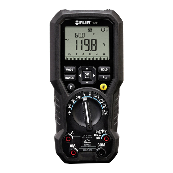
3. Introduction Thank you for selecting the FLIR DM90 True RMS Digital MultiMeter with Type-K thermocouple and work light features. The DM90 can measure voltage up to 1000V AC/DC and includes Low-Z (low impedance), VFD (low pass filter), Non-Contact Voltage Detector, and Smart/Classic Diode modes. -
Page 7: Meter Description
13. Cancel/Return Button 14. Display HOLD Button 1. Test Lead holder attachment mounts 2. Tripod mount (test lead holder attaches here also) 3. Tilt Stand (Battery Compartment located beneath the stand) Fig. 4-2 Rear View FLIR DM90 USER MANUAL Document Identifier: DM90-en-US_AA... -
Page 8: Function Switch Positions
Measure current through the probe inputs (A or mA). Use the MODE button to select AC or DC. Measure µA current through the probe inputs. Use the MODE button to select AC or DC. Fig. 4-3 Function Switch FLIR DM90 USER MANUAL Document Identifier: DM90-en-US_AA... -
Page 9: Function Buttons And Selector/Navigation Pad
Press to enable/disable the work light. 4.3.1 MODE Button Operation Switch Position MODE button sequence of operation AC → DC → °F or °C Resistance → Continuity → Capacitance → Diode AC → DC AC → DC FLIR DM90 USER MANUAL Document Identifier: DM90-en-US_AA... -
Page 10: Selector/Navigation Pad Operation
In Settings mode, the left/right buttons are used to change the value of an option The UP/DOWN buttons: In normal mode, the up/down buttons have no function In Settings mode, the up/down buttons are used to change an option. 4.4 Display Description Fig. 4-5 Display Icons FLIR DM90 USER MANUAL Document Identifier: DM90-en-US_AA... -
Page 11: Display Icons And Indicators
Auto range mode Data Hold mode. Primary display (large digits) Secondary display (smaller digits) Battery voltage status Auto power off function enabled AC current or voltage DC current or voltage Flex Clamp Direct Input FLIR DM90 USER MANUAL Document Identifier: DM90-en-US_AA... -
Page 12: Probe Detection Alert
‘Prob’ is shown. 4.5.2 Out-of-range warning If the input is over/under the full-scale range in Manual range mode, or if the signal has exceeded the maximum/minimum input in Auto range mode, ‘OL’ is displayed. FLIR DM90 USER MANUAL Document Identifier: DM90-en-US_AA... -
Page 13: Menu Icon Bar
4. In the AC Voltage/AC mV/AC Current/Flex/LoZ modes all icons shown above are available. 5. For DC Current/Voltage, Resistance, Continuity, Capacitance, Temperature, and Diode only the MAX-MIN-AVG, Relative, and Settings icons are available. FLIR DM90 USER MANUAL Document Identifier: DM90-en-US_AA... -
Page 14: Operation
To change the range, press the button repeatedly until the desired range is displayed. 2. To return to the Auto range mode, long press the button until the Auto Range indicator is again displayed. FLIR DM90 USER MANUAL Document Identifier: DM90-en-US_AA... -
Page 15: Voltage And Frequency Measurements
To display only the Frequency, navigate to using the arrow buttons and enable the mode by pressing OK. Fig. 5-1 Voltage and Frequency Measurements FLIR DM90 USER MANUAL Document Identifier: DM90-en-US_AA... -
Page 16: Resistance Measurements
5. If the resistance is < 20Ω the meter beeps. If the resistance is > 200Ω the meter will not beep. > 20Ω but < 200Ω the beeping will stop at an unspecified point. Fig. 5-2 Resistance and Continuity Measurements FLIR DM90 USER MANUAL Document Identifier: DM90-en-US_AA... -
Page 17: Classic Diode Test
5. If the reading is between 0.400 and 0.800V in one direction and OL (overload) in the opposite direction, the component is good. If the measurement is 0V in both directions (shorted) or OL in both directions (open), the component is bad. Fig. 5-3 Classic Diode Measurements FLIR DM90 USER MANUAL Document Identifier: DM90-en-US_AA... -
Page 18: Smart Diode Test
The meter display will show ± 0.400 ~ 0.800V for a good diode, ‘bAd’ for a shorted diode, and ‘O.L’ for an opened diode. See Fig. 5.4 below: Fig. 5-4 SMART Diode Test FLIR DM90 USER MANUAL Document Identifier: DM90-en-US_AA... -
Page 19: Capacitance Measurements
5. Read the capacitance value on the display. Note: For very large capacitance values, it may take several minutes for the measurement to settle and the final reading to stabilize. Fig. 5-5 Capacitance Measurements FLIR DM90 USER MANUAL Document Identifier: DM90-en-US_AA... -
Page 20: Type K Temperature Measurements
5. Read the temperature value on the display. 6. To avoid electrical shock, disconnect the thermocouple adapter before turning the function switch to another position. Fig. 5-6 Temperature Measurements FLIR DM90 USER MANUAL Document Identifier: DM90-en-US_AA... -
Page 21: Current And Frequency Measurements
5. Read the current and frequency values on the display (note that the frequency function is not available for the µA function). To display only the Frequency, navigate to Hz using the arrow buttons and enable the mode by pressing OK. FLIR DM90 USER MANUAL Document Identifier: DM90-en-US_AA... - Page 22 Fig. 5-8 High Current ‘A’ and Frequency Measurements FLIR DM90 USER MANUAL Document Identifier: DM90-en-US_AA...
- Page 23 Fig. 5-9 mA Current and Frequency Measurements Fig. 5-10 uA Current Measurements FLIR DM90 USER MANUAL Document Identifier: DM90-en-US_AA...
-
Page 24: Flex Clamp Adaptor Current Measurements
3. Set the Range of the Flex Clamp Adaptor to match the range of the DM90. 4. Use the RANGE button to select the range of the DM90 (1, 10, 100 mv/A). The selected range will be shown on the right side of the DM90 display. -
Page 25: Non-Contact Voltage Detector
4. Position the top of the meter close to a source of voltage or electromagnetic field. 5. When a voltage or electromagnetic field is detected the meter will emit a continuous tone. Fig. 5-12 Non-Contact Voltage Detector FLIR DM90 USER MANUAL Document Identifier: DM90-en-US_AA... -
Page 26: Mode Icons And The Menu Bar
In Min/Max/Avg mode, the meter captures and displays the minimum, maximum, and average readings, updating only when a higher/lower value is registered. The meter also averages the total sum of all recorded values. FLIR DM90 USER MANUAL Document Identifier: DM90-en-US_AA... -
Page 27: Frequency Mode (Acv And Aca Only)
Coarse Resolution (C.r. ON/OFF). Use the arrow buttons to select ON (to limit the least significant display digits) or OFF (to display with maximum resolution). Reset (rSt): Press OK to revert to the factory default settings. FLIR DM90 USER MANUAL Document Identifier: DM90-en-US_AA... -
Page 28: Data Hold And Auto Hold
Current > 1% full scale Capacitance > 1% full scale Resistance With ‘OL’ not displayed Diode With ‘OL’ not displayed Temperature With ‘OL’ not displayed To enter/exit Auto hold mode, press the button FLIR DM90 USER MANUAL Document Identifier: DM90-en-US_AA... -
Page 29: Maintenance
As with most electronic products, this equipment must be disposed of in an environmentally friendly way, and in accordance with existing regulations for electronic waste. Please contact your FLIR Systems representative for more details. FLIR DM90 USER MANUAL Document Identifier: DM90-en-US_AA... -
Page 30: Specifications
Circuits directly connected to a low-voltage installation. Building installation. Source of the low-voltage installation. EMC: EN 61326-1 Pollution degree: 2 Drop protection: 9.8’ (3m) Max. Operating Altitude: 6562 ft. (2000m) Vibration: Random Vibration per MILPRF28800F Class 2 FLIR DM90 USER MANUAL Document Identifier: DM90-en-US_AA... -
Page 31: Electrical Range Specifications
Freq. Response 6.000V 6.600V 0.001V ±(1.0% + 3D) 45Hz ~ 500Hz 60.00V 66.00V 0.01V 600.0V 660.0V 0.1V ±(1.0% + 3D) 45Hz ~ 1kHz 1000V 1100V Input Impedance: 10MΩ (< 100pF) Overload Protection: AC/DC 1000V FLIR DM90 USER MANUAL Document Identifier: DM90-en-US_AA... - Page 32 Maximum measurement time: > 5A for max. 3 minutes with at least 20-minute rest time. > 10A for max.30 seconds with at least 10-minute rest time. Overload Protection: AC/DC 11A for A terminal. AC/DC 660mA for mA terminal. FLIR DM90 USER MANUAL Document Identifier: DM90-en-US_AA...
- Page 33 6.600kΩ 0.001kΩ ±(0.9% + 2D) 60.00kΩ 66.00kΩ 0.01kΩ ±(0.9% + 2D) 600.0kΩ 660.0kΩ 0.1kΩ ±(0.9% + 2D) 6.000MΩ 6.600MΩ 0.001MΩ ±(0.9% + 2D) 50.00MΩ 55.00MΩ 0.01MΩ ±(3.0% + 5D) Overload Protection: AC/DC 1000V FLIR DM90 USER MANUAL Document Identifier: DM90-en-US_AA...
- Page 34 100mV Unspecified 6.000V 0.6V Unspecified 60.00V Unspecified 600.0V 100V Unspecified 1000V 600V Unspecified Unspecified ACA - Minimum Sensitivity: Range 5Hz ~ 10kHz >10kHz 60.00mA 10mA Unspecified 600.0mA 60mA Unspecified 6.000A Unspecified 10.00A Unspecified FLIR DM90 USER MANUAL Document Identifier: DM90-en-US_AA...
- Page 35 Accuracy specification assumes surrounding temperature stable to ±1 °C. For surrounding temperature changes of ± 2 °C, rated accuracy applies after 2 hours. Accuracy specified for use with work light and backlight off only. Overload Protection: AC/DC 1000V. FLIR DM90 USER MANUAL Document Identifier: DM90-en-US_AA...
-
Page 36: Technical Support
Accuracy is unspecified for > 400Hz Cut-off Frequency: 800Hz 8. Technical Support Main Website http://www.flir.com/test Technical Support Website http://support.flir.com Technical support Email TMSupport@flir.com Service/Repair Support Email Repair@flir.com Support Telephone number +1 855-499-3662 option 3 (toll-free) FLIR DM90 USER MANUAL Document Identifier: DM90-en-US_AA... -
Page 37: Warranty
Purchaser, and for the cost of repackaging and returning the Product to Purchaser. Any non-warranty repair of a Product is warranted for one hundred eighty days (180) days from the date of return shipment by FLIR to be free from defects in materials and workmanship only, subject to all of the limitations, exclusions and disclaimers in this document. - Page 38 Technical Support Website http://support.flir.com Technical Support Email TMSupport@flir.com Service and Repair Email Repair@flir.com Customer Support Telephone +1 855-499-3662 option 3 (toll free) Publication Identification No.: DM90-en-US Release Version: Release Date: January 2017 Language: en-US FLIR DM90 USER MANUAL Document Identifier: DM90-en-US_AA...
Need help?
Do you have a question about the DM90 and is the answer not in the manual?
Questions and answers