Advertisement
Table of Contents
- 1 Table of Contents
- 2 Important Information
- 3 Warnings and Precautions
- 4 Technical Data
- 5 Checklist of Enclosures
- 6 Installation and Commissioning
- 7 Operating Instructions
- 8 Cleaning
- 9 Servicing, Maintenance and Component Replacement
- 10 Conversion Instructions
- 11 Fault Finding
- 12 Spare Parts List
- 13 Service Information and Guarantee
- Download this manual
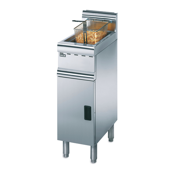
Installation, Operating and Servicing
Instructions
Silverlink 600 Free Standing Gas Fryers
J5 – A008, J10 – A009
Please make a note of your product details for
future use:
Date Purchased:_________________________
Model Number:__________________________
Serial Number:__________________________
Dealer:_________________________________
_______________________________________
IS 678 ECN 4993
Page 1 of 20
Advertisement
Table of Contents


Need help?
Do you have a question about the A009 and is the answer not in the manual?
Questions and answers