
Related Manuals for Lincat Silverlink 600 DC04


Summary of Contents for Lincat Silverlink 600 DC04
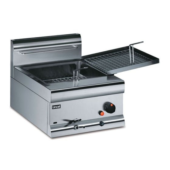
- Page 1 Utensils Direct - 01903 823888 www.utensilsdirect.co.uk User, Installation and Servicing Instructions Silverlink 600 Gas Fryers DF4 and DC04 IS355 ECN3592...
-
Page 2: Customer Information
Details are available from your local distributor or direct from us. Used for the purposes for which it is intended, and with careful maintenance as outlined in this User Guide, your Lincat product will give you years of trouble free service. IMPORTANT INFORMATION Please read all of the safety and operating instructions carefully before using this product. -
Page 3: Table Of Contents
CONTENTS Contents Page Customer Information………………………………………………………. Warnings and Precautions………………………………………………… Technical Data……………………………………………………………….. Commissioning………………………………………………………………. Check List of Enclosures………………………………………………….. Installation…………………………………………………….………………. User…………………………………………………………………………….. 8-12 Servicing ……………………………………………………………………… 12-13 Component Replacement ………………………………………….……… 14-15 Spare Parts List……………………………………………………………… Fault Finding…………………………………………………………………. 16-17 Service information………………………………………………………….. Guarantee………………………………………………………….………….. WARNINGS AND PRECAUTIONS It is mandatory that all appliances are installed, commissioned and serviced by a qualified and competent person as defined by the regulations in force in the country of installation. -
Page 4: Technical Data
It is recommended that a room, or internal space, be provided with a minimum free area of 4.5cm per kW of total heat input. OPERATIONAL CHECK Although all Lincat fryers are functionally checked during manufacture, commissioning must include a functional check of all controls. IS355 ECN3592... -
Page 5: Check List Of Enclosures
Connection Nipple (1/2" BSP) User Instructions SERIAL NUMBER Each appliance manufactured at Lincat has a unique identifying number found in NOTE the top right hand corner of the data plate attached at the rear of the appliance. Please record that number in the space provided should it be required for future reference. - Page 6 GAS SUPPLY AND CONNECTION Check that the gas supply corresponds to that specified on the data plate. Connection is at the rear of the unit via a 1/2" G male thread. If connection to the supply pipe is via a flexible hose, ensure that the hose used is suitable for commercial catering appliances.
- Page 7 Fig 2. ADJUSTING BURNER PRESSURE After removing the facia panel, (Fig 1) access to the pressure test points on the gas valves can be obtained. Using the test point (Fig 2, A), remove the blanking screw and attach a pressure gauge to the boss of the test nipple, to check supply inlet pressure.
-
Page 8: User
USER INSTRUCTION APPLIANCE USE This appliance is only for professional use and should only be used by qualified personnel. Ensure that the person responsible understands how to light, safely operate, clean and shutdown the appliance and is made aware of the position and operation of the gas isolating cock in the event of an emergency. - Page 9 LIGHTING SEQUENCE Please ensure that the gas isolation valve for the appliance is turned to the open position before attempting to light this unit. 1. Ensure that the thermostat control knob (Fig 3, 1) is in the OFF position. 2. Ensure the gas valve control knob (Fig 3, 2) is in the off position. 3.
- Page 10 DRAINAGE Always allow the oil to cool to a maximum 55 C before draining. Remove the blanking nut from the front of the unit (Fig 3, 5). Fit the drain pipe, which has a stowage clip under the lid, and place a suitable receptacle under the pipe outlet.
- Page 11 The life of oil or fat will also be extended if the temperature is turned down when the fryer is not in use - otherwise if left "full-on" the oil is being subjected to needless heat treatment and thereby destroyed. Used oil symptoms firstly indicate discolouration by darkening.
-
Page 12: Servicing
SERVICING ROUTINE SERVICE We recommend that competent authorised service agents carry out all servicing, other than routine cleaning. In addition to that, a service should take place every 6 months. Please see page 18 “Service” for information on authorised service agents. ... - Page 13 The body and hob are interlocked by 3 steel hooks and slots on each side – to separate, push hobtop back until hooks disengage the lift hob and tank assumedly clear of the base and sides. Take care as the limit thermostat and safety stat will remain attached to hobtop – do not damage the capillaries.
-
Page 14: Component Replacement
Fig 5 Carry out any work necessary and reassemble in reverse order. COMPONENT REPLACEMENT High limit thermostat Remove the facia panel see (Fig 1). Undo tank gland. Undo limit thermostat nut and withdraw phial from bracket. ... - Page 15 Replace in reverse order, ensuring correct phial location within the tank bracket. Control Valve (Fig 5, 2) Removal of the hobtop and facia as per (Fig, 5). Disconnect all wires connections on valve terminals. Undo pilot feed pipe. ...
-
Page 16: Spare Parts List
Fig 6 Thermocouple (Fig 6, D) After separating, the pilot assembly steps 1 – 4. Undo thermocouple retaining nut and remove from pilot assembly. Disconnect at interrupter and withdraw thermocouple. Thermopile (Fig 6, B) After separating, the pilot assembly steps 1 - 4. ... -
Page 17: Fault Finding
The following components are listed with Lincat reference part number. Description Part number Piezo Igniter IG12 Igniter lead IG06 Igniter Electrode IG15 Pilot Assembly PI08 Thermopile TC20 Interrupted Thermocouple TC38 Control Thermostat TH95 Safety limit Thermostat TH96 Gas Control Valve... -
Page 18: Service Information
Are the thermocouple/Interrupter connections secure. Yes. Is there gas at the pilot when holding control knob in the Tighten connection. pilot position. Yes. Very little. Check supply. Check overtemperature Check supply. stat for open circuit. Check pilot jet for Check thermocouple blockage and clean where voltage (minium 15mV). -
Page 19: Guarantee
Gas catering equipment should be routinely serviced to ensure a long trouble free life. It is recommended that this appliances is serviced every 6 months by a competent gas engineer. For help regarding the installation, maintenance and use of your LINCAT equipment, please call:- Utensils Direct - 01903 823888... - Page 20 Notes IS355 ECN3592...
Need help?
Do you have a question about the Silverlink 600 DC04 and is the answer not in the manual?
Questions and answers