
Related Manuals for RKI Instruments 65-2422RK-05


Summary of Contents for RKI Instruments 65-2422RK-05
- Page 1 65-2422RK-05 Hydrogen Sulfide Transmitter Operator’s Manual Part Number: 71-0114RK Revision: D Released: 6/12/20 1.888.610.7664 www.calcert.com sales@calcert.com...
- Page 2 Typical calibration frequen- cies for most applications are between 3 and 6 months, but can be required more often or less often based on your usage. 2 • 65-2422RK-05 H S Transmitter 1.888.610.7664 www.calcert.com...
- Page 3 Product Warranty RKI Instruments, Inc. warrants gas alarm equipment sold by us to be free from defects in materials, workmanship, and performance for a period of one year from date of shipment from RKI Instruments, Inc. Any parts found defective within that period will be repaired or replaced, at our option, free of charge.
-
Page 4: Table Of Contents
Parts List ..............20 4 • 65-2422RK-05 H S Transmitter 1.888.610.7664... -
Page 5: Overview
WARNING: When using the 65-2422RK-05, you must follow the instructions and warnings in this manual to assure proper and safe operation of the 65-2422RK-05 and to minimize the risk of personal injury. Be sure to maintain and periodically calibrate the 65-2422RK-05 as described in this manual. -
Page 6: Description
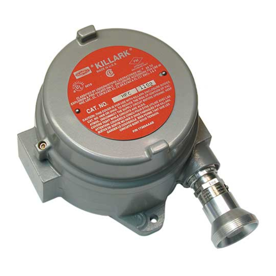
SP AN Hydrogen T OXIC Sulfide T OXIC Amplifier Jumper Block Installed To Toxic Securing Select Header Screw (2) Detector Terminal Strip Hydrogen Sulfide Detector Figure 1: H S Transmitter Component Location 6 • 65-2422RK-05 H S Transmitter 1.888.610.7664 www.calcert.com sales@calcert.com... -
Page 7: H 2 S Detector
Rubber Boot and Spacer A rubber boot and spacer are installed between the detector housing cap and the sensor. They help ensure that the detector remains plugged into the detector housing body. 65-2422RK-05 H S Transmitter • 7 1.888.610.7664 www.calcert.com... -
Page 8: Amplifier
The zero pot is above the span pot. Use the zero pot to adjust the transmitter’s target gas-free output during the start-up and calibration procedures. CAUTION:The third potentiometer is factory-set. Do not adjust it. 8 • 65-2422RK-05 H S Transmitter 1.888.610.7664 www.calcert.com... -
Page 9: Junction Box
• Select a site where the target gas is likely to be found first. NOTE: If your application does not require a specific mounting site, mount the transmitter at approximately breathing level. 65-2422RK-05 H S Transmitter • 9 1.888.610.7664 www.calcert.com... - Page 10 5. At the monitoring site, use #10 screws through the junction box’s two mounting holes to secure the junction box to a vertical surface. CAUTION:Mount the H S transmitter with the detector facing down (see Figure 2). 10 • 65-2422RK-05 H S Transmitter 1.888.610.7664 www.calcert.com...
-
Page 11: Wiring The H 2 S Transmitter To A Controller
S transmitter through one of the conduit hubs at the controller housing. CAUTION:Do not route power and transmitter wiring through the same conduit hub. The power cable may disrupt the transmission of the transmitter signal to the controller. 65-2422RK-05 H S Transmitter • 11 1.888.610.7664 www.calcert.com sales@calcert.com... - Page 12 11. If shielded cable is used, connect the cable’s drain wire to an available chassis (earth) ground at the controller. RKI controllers typically have a ground stud that can be used to ground the cable’s drain wire. 12 • 65-2422RK-05 H S Transmitter 1.888.610.7664 www.calcert.com...
-
Page 13: Startup
The procedure below describes applying zero emission air, usually called zero air, using a calibration kit that includes a calibration cup, calibration gas, sample tubing, and a fixed flow regulator with an on/off knob. RKI Instruments, Inc. recommends using a 0.5 LPM (liters per minute) fixed flow regulator. -
Page 14: Maintenance
The controller indicates a fail condition. Probable causes • The transmitter wiring is disconnected or misconnected. • The transmitter’s zero reading is low enough to cause a fail condition. • The transmitter is malfunctioning. 14 • 65-2422RK-05 H S Transmitter 1.888.610.7664 www.calcert.com sales@calcert.com... -
Page 15: Replacing Components Of The H S Transmitter
1. Verify that the calibration cylinder contains an adequate supply of a fresh test sample. 2. If the calibration/response difficulties continue, replace the H S sensor as described later in this section. 3. If the calibration/response difficulties continue, contact RKI Instruments, Inc. for further instruction. Replacing Components of the H S Transmitter This section includes procedure to replace the H S sensor and amplifier. - Page 16 Table 2: Reconnecting the H S Amplifier to a Controller Amplifier Interconnect Controller Transmitter Terminal Strip Terminal Strip (typical) 4/20 FB 4 -20 (FB) 24V + + V (11 - 30 VDC) 16 • 65-2422RK-05 H S Transmitter 1.888.610.7664 www.calcert.com sales@calcert.com...
- Page 17 S Detector to the Amplifier Amplifier Interconnect S Detector Lead Terminal Strip Black TOXIC BK TOXIC RD 8. Reinstall the junction box cover. 9. Turn on or plug in incoming power at the controller. 65-2422RK-05 H S Transmitter • 17 1.888.610.7664 www.calcert.com sales@calcert.com...
-
Page 18: Calibration Frequency
It describes the test using a calibration kit that includes a calibration cup, calibration gas, sample tubing, and a fixed flow regulator with an on/off knob. RKI Instruments, Inc. recommends using a 0.5 LPM (liters per minute) fixed flow regulator. -
Page 19: Setting The Zero Reading
5. If necessary, use the span pot on the amplifier to adjust the reading to match the correct response reading. 6. Turn the regulator on/off knob clockwise to close it. 7. Unscrew the regulator from the calibration cylinder. 8. Unscrew the calibration cup from the detector. 65-2422RK-05 H S Transmitter • 19 1.888.610.7664 www.calcert.com sales@calcert.com... -
Page 20: Returning To Normal Operation
Regulator with gauge and knob, 0.5 LPM, for 34 liter aluminum calibration cylinders and 58 liter and 103 liter steel calibration cylinders (cylinders with internal thread) 81-1117RK Calibration cup ES-1537-H2S S replacement sensor 20 • 65-2422RK-05 H S Transmitter 1.888.610.7664 www.calcert.com sales@calcert.com...
Need help?
Do you have a question about the 65-2422RK-05 and is the answer not in the manual?
Questions and answers