
Related Manuals for RKI Instruments RI-600


Summary of Contents for RKI Instruments RI-600
- Page 1 RI-600 Indoor Carbon Dioxide Monitor Operator’s Manual Part Number: 71-0517 Revision: 0 Released: 11/7/22...
-
Page 2: Table Of Contents
Contents 1 Outline of the Product ............................. 3 Preface ................................3 Purpose of use ..............................3 Definition of DANGER, WARNING, CAUTION and NOTE ................4 Method of confirmation for CE marking type ....................4 (DC specification only)............................ 4 2 Important Notices on Safety..........................5 2-1. -
Page 3: Outline Of The Product
Outline of the Product Preface Thank you for choosing our indoor carbon dioxide monitor RI-600. Please verify that the model number of the product you purchased is included in the specifications on this manual. This manual describes the monitor’s specifications and instructions on proper use. All users must read and understand the operating manual before using the detector. -
Page 4: Definition Of Danger, Warning, Caution And Note
Definition of DANGER, WARNING, CAUTION and NOTE This message indicates that improper handling may cause serious DANGER damage to life, health, or assets. This message indicates that improper handling may cause serious WARNING damage to health or assets. This message indicates that improper handling may cause minor CAUTION damage to health or assets. -
Page 5: Important Notices On Safety
Important Notices on Safety WARNING • If an abnormality is found in the monitor, contact RKI immediately. 2-1. Danger Statements DANGER • This is not an explosion-proof unit. Never attempt to measure a gas in an atmosphere over the lower explosive limit. 2-2. -
Page 6: Caution Statements
2-3. Caution Statements CAUTION • Do not use a device, such as a transceiver, which transmits a radio wave near the monitor or its cables. It may affect the measurement. If a transceiver or other radio wave transmitting device is used, it must be used in a place away from the monitor. -
Page 7: Product Components
After unpackaging the unit, check the monitor and accessories. If there is anything missing, contact RKI. Main unit For names and functions of individual parts of the monitor and LCD display, see "3-2. Names and functions for each part" (P.9). RI-600... - Page 8 Standard accessories - Cross-recessed pan head - 3.2 m AC power cable (1 pc.) *Supplied only with AC machine screw (2 pcs.) specification - Cross-recessed round head - Operating manual (1 pc.) wood screw (2 pcs.) CAUTION • The main unit and sensor unit (remote type) are precision devices. Be careful not to drop the monitor when installing or uninstalling the main unit or sensor unit.
-
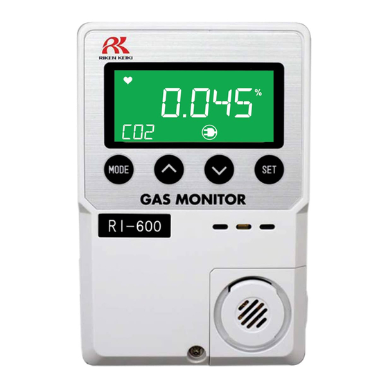
Page 9: Names And Functions For Each Part
3-2. Names and functions for each part This section describes the names and functions of the individual parts and LCD display that make up the monitor. Main unit Name Major function Turns the power ON/OFF. Slide the switch up to power on and Power switch down to power off. - Page 10 Display Name Major function Operating state display Displays the operating status. Blinks in normal operation. 1st alarm display Lights up or flashes orange during a first alarm state. 2nd alarm display Lights up or flashes red during a second alarm state. Fault alarm display Lights up red during a fault alarm state.
-
Page 11: How To Install
How to Install 4-1. Precautions for installation points When installing the monitor, observe the following precautions. Ignoring these precautions may damage the monitor, resulting in inaccurate gas detection. CAUTION • This is a precision device. Because the monitor may not provide the specified performance in some places (environments), check the installation environment, then take appropriate actions if necessary. -
Page 12: Precautions For System Designing
<Do not install the monitor in a place where maintenance of the monitor cannot be performed or where handling the monitor involves dangers.> Regular maintenance of the monitor must be performed. Do not install the monitor in a place where the machinery must be stopped when maintenance is performed, where parts of the machinery must be removed to perform maintenance, or where the monitor cannot be removed because racks or other things prevent access to it. - Page 13 - In addition, the surge absorbing part SK2 must be attached to the loaded side of the external relay if necessary. - For certain load conditions, it is recommended that the surge absorbing part be attached to the contact. It must be attached to an appropriate location by checking how the load is activated. RI-600 Alarm contact Power Power...
-
Page 14: Installation Of Main Unit
4-3. Installation of main unit Install the main unit on the wall 50-180 cm from the floor. If wall screws are available, remove the screw at the lower part of the main unit to open the cover and install the unit using the mounting holes on the back of the unit. CAUTION •... - Page 15 <Maintenance Space> If the installation board (option) is used, secure an installation space above the unit so that it can be installed by sliding. Secure as installation space Installation dimension drawing (Installation board not used) Installation dimension drawing (Installation board used) Compatible with JIS single switch box...
-
Page 16: Precautions For Wiring
4-4. Precautions for wiring If the monitor operates on AC or DC power, or inductive load is used at the alarm contact, wiring work is required. The following cables are recommended for wiring the monitor with the power supply, signal cable and contact. - Page 17 How to connect to terminal plate When cables (wires) are connected to the terminal plate inside the main unit, use the dedicated screwdriver or a compatible flathead screwdriver. When connecting a stranded wire, be sure to press the push button and open the spring while connecting the wire.
- Page 18 Figure of terminal plate The overview of the terminal plate inside the main unit is as follows: For contact (TN3) For external output signal 1 - 2: ALM1 (First) (4 - 20 mA/0 - 1 V) (TN2) 3 - 4: ALM2 (Second) 1: (+) 2: (-) <For Connecting AC Power>...
-
Page 19: How To Use
How to Use 5-1. Before using the monitor Users must follow the operating precautions. Ignoring the precautions may damage the monitor, resulting in inaccurate gas detection. CAUTION • After you have received the monitor, start using the monitor within the specified operation start limit of its sensor. -
Page 20: Basic Operating Procedures
5-3. Basic operating procedures Normally, the detection mode is activated after the power is turned on. <Detection Mode> The monitor is restarted after recovering from fault. CO2 (long press) <Gas Alarm Status> <User Mode> CO2 <Fault Alarm Status> <Maintenance Mode> CO2 (long press) WARNING... -
Page 21: Power-On
5-4. Power-on - Before turning on the power switch, check that the monitor is installed properly. - Slide the power switch up to power on the monitor. - After the monitor completes the start-up, it enters the detection mode. Power switch <Start-up Procedures (approximately 25 seconds for system check of the monitor and alarm deactivation)>... -
Page 22: Modes
5-5. Modes Mode Item LCD display Details Detection concentration Normal state - mode Gas name Version display 1-0 VER Indicate the program version. Fresh air 1-1 AIR Not used. adjustment Show the typical settings. 1-20: First Alarm Setpoint (ALM1) 1-21: Second Alarm Setpoint (ALM2) User Mode 1-22: Alarm Delay Time (DELY) Setting display... -
Page 23: User Mode
5-6. User mode WARNING • After adjustment is completed, press the MODE button to return to detection mode. (The monitor automatically returns to detection mode in ten hours.) Detection mode Press the MODE button for three seconds. CO2 User mode 1-0. - Page 24 <Setting Display "1-2"> This is used to check the setting of typical menus. 1-2. CONF Press the SET button. First Alarm Setpoint Display Press the SET button to display the first alarm setpoint. Second Alarm Setpoint Display Alarm Delay Time Display (seconds) Zero Suppression Value Display...
-
Page 25: Power-Off
Zero Follower ON/OFF Display Not used. Air Pressure Correction ON/OFF Display Not used. Alarm Summary 5-7. Power-off Slide the power switch down to power off. After turning off the power switch of the monitor, turn off the power supply (100 VAC or 24 VDC) of the monitor. -
Page 26: Alarm Activation And Functions
Alarm Activation and Functions 6-1. Gas alarm activation A gas alarm is activated when detected gas concentration reaches the preset alarm setpoint. NOTE • The alarm setpoint (first alarm and second alarm) is factory-set. The setting values can be changed in the maintenance mode (P.30). -
Page 27: Fault Alarm Activation
6-2. Fault alarm activation A fault alarm is triggered when an abnormality is detected in the monitor. After a fault alarm is triggered, FAULT is displayed and the backlight (red) lights up on the LCD. An error message displays on the LCD. Determine the cause(s) and take appropriate actions. After the monitor is successfully returned from the fault, it restarts and goes through an initial clear procedure. -
Page 28: Peak Hold Operation
6-4. Peak hold operation The Peak hold function allows the user to check the highest CO2 reading since the last time the monitor was cleared. ˄ ˄ 1. While in detection mode, press the button to activate the Peak hold function. ˄... -
Page 29: Maintenance
Maintenance The monitor is an important instrument for the purpose of safety. To maintain the performance of the monitor and improve the reliability of safety, perform a regular maintenance. 7-1. Maintenance intervals and items This is a safety unit. Make sure to perform daily and regular maintenance before use. ・... -
Page 30: Maintenance Mode
7-2. Maintenance mode The maintenance mode allows for checking the status of the monitor and adjusting and changing the settings. WARNING • When the adjustment is completed, press the MODE button to return to detection mode. The monitor automatically returns to detection mode after 10 hours. Item LCD display Details... - Page 31 <Entering Maintenance Mode> From measuring mode, press and hold the MODE button for 3 seconds. Press the ˄ button until the “1-3 MMOD” screen appears. Press the SET button in "1-3. M MOD". Then press the SET button again for three (long press) seconds.
- Page 32 2-0. GAS TEST Perform a test with the gas. Similar to the detection condition, the reading changes and an alarm is displayed after gas is introduced, but the “ALM1” and “ALM2” do not flash and the contact is not activated. 2-1.
- Page 33 2-3. SDEF Not used. 2-4. SET Specify various settings. 2-5. DISP Provide various detail displays. 2-6. F MODE Not used. 2-7. U MODE Return to the user mode.
- Page 34 <Test Functions> 2-0. GAS TEST Perform a test with the gas. Similar to the detection mode, the reading changes and an alarm is displayed after the gas is introduced, but the contact is not activated. 2-00. GAS Perform the gas test. 2-01.
- Page 35 2-03. LCD Perform the LCD display test. 2-04. Not used. To 2-00...
-
Page 36: Preparing For A Zero And Span Adjustment
・CO2 calibration cylinder with a concentration near 50% of the full scale Procedure 1. Screw the fixed flow regulator into the calibration cylinder. 2. Use the calibration tubing to connect the regulator to the calibration cup’s inlet. 3. Attach the calibration cup to the RI-600. -
Page 37: Performing A Zero Adjustment
7-4. Performing a Zero Adjustment 2-1. ZERO Navigate to the zero adjustment menu item in Maintenance Mode (see page 31). Press the SET button. The current concentration is displayed. Turn the regulator’s knob counterclockwise to open the regulator. Allow the N2 gas to flow for 2 minutes. -
Page 38: Performing A Span Adjustment
7-5. Performing a Span Adjustment 2-2. SPAN Navigate to the span adjustment menu item in Maintenance Mode (see page 31). Press the SET button. The current concentration is displayed. Turn the regulator’s knob counterclockwise to open it. Allow gas to flow for 2 minutes. -
Page 39: Environmental Setting
7-6. Environmental Setting 2-4. SET Specify various settings. 2-40. Not used. 2-41. Not used. 2-42. AL-P Set the alarm setpoint Use the ˄ or ˅ button (first, second). to set the alarm setpoint and press the SET button to confirm... - Page 40 2-43. AL-D Set the alarm delay Use the ˄ or ˅ button time (seconds). to set the time (seconds) and press the SET button to confirm it. 2-44. AL-T Not used. 2-45. SP-T Not used. 2-46. SAPP S Not used.
- Page 41 2-47. Not used. 2-48. MA20 Adjust the external output (4 mA, 20 mA). Then, use the ˄ or ˅ Connect an ammeter. button to select the value and press the SET button to confirm 2-48. MA20 Adjust the external output (4 mA, 20 mA). Then, use the ˄...
- Page 42 2-4A. DATE Use the ˄ or ˅ button Set the date/time. to select each value in the order of year, month, day, hour and minute and press the SET button to confirm...
- Page 43 2-4b. P-A Not used. 2-4C. ACAL Not used. 2-4d. BZZR Set the buzzer to ON/OFF.
- Page 44 2-4E. AL-R Set the gas alarm state contact to ON/OFF. 2-4F. MA-O Set the external output signal to ON/OFF.
- Page 45 2-4H. LCD Set the LCD backlight to ON/OFF. No backlight by standard setting...
-
Page 46: Component Replacement
7-7. Component Replacement <Replacing the Sensor (Integrated Sensor Type)> Remove the sensor cover of the sensor part. Sensor cover Insert a coin straight to the recessed area at the lower right of the monitor to release the sensor cover’s latch. Remove the sensor cover. - Page 47 Remove the old sensor. Install the new sensor. Be sure the sensor pins are lined up with the board’s sockets. Put the sensor cover back CAUTION • When installing the sensor, be sure the pins are lined up with the sockets before pushing in the sensor.
- Page 48 The wire colors in the extender cable may vary depending on the type of cable used. The Type A cable has red/green/white/black wires, and the Type B cable has white/yellow/white/blue wires. The pictures in this section show the Type A cable. Turn off or disconnect power to the RI-600. Remove the top half of the main unit’s housing.
- Page 49 Remove the cable plug from the cable socket on the sensor board. Press the tab on the plug to release it and pull it away from the socket. Unplug the wires from the sensor terminal strip. For each terminal strip position: - Push the pushbutton straight downward using the compatible screwdriver...
- Page 50 To remove the sensor board, insert a compatible screwdriver into the back of the RI-600 housing as shown in the figure to the right. Press down on the PCB retaining tab. The sensor board should fall out when the retaining tab is pushed down.
- Page 51 Connect the cable plug into the sensor board. Secure the sensor cover of the new cable’s remote sensor housing. Route the new remote cable’s wiring through the hole in the housing to the right of the sensor terminal strip and install a zip tie in the case and around the cable as shown in the image to the right, but do...
- Page 52 Type B cable has white/yellow/white/blue wires. The pictures in this section show the Type A cable. Turn off or disconnect power to the RI-600. Remove the sensor cover of the old cable’s remote sensor housing.
- Page 53 Remove the top half of the main unit’s housing to access the wiring at the other end of the cable. Remove the old cable’s wiring leads from the sensor terminal strip. For each terminal strip position: Push the push button straight downward using the compatible screwdriver or equivalent to open the spring.
- Page 54 Connect the cable’s wires to the sensor terminal strip. See the table below for the wire colors. Type A wire colors are shown in the image to the right. Note that the Type B cable has two pairs of wires extending from the cable.
-
Page 55: Storage And Disposal
Storage and Disposal 8-1. Procedures to store the monitor or leave it for a long time The monitor must be stored under the following environmental conditions. • In a dark place under the normal temperature and humidity away from direct sunlight •... -
Page 56: Troubleshooting
Troubleshooting This Troubleshooting guide does not explain the causes of all malfunctions which may occur on the monitor. This simply helps to find the causes of the monitor’s most frequent malfunctions. If the monitor shows a symptom which is not explained in this manual or still has malfunctions even after remedial actions are taken, please contact RKI. -
Page 57: Product Specifications
Product Specifications 10-1. List of specifications Detection principle Non-Dispersive Infrared Ray Gas to be detected Carbon dioxide Concentration display LCD digital display (Five-digit, seven-segment/green, orange and red backlight) No backlight by standard setting Detection range 0 – 2000 ppm / 0 – 5000 ppm / 0 – 10000 ppm 0 –... -
Page 58: Spare Parts List
Spare Parts List Part Number Description 06-1248RK-03 Calibration tubing, 3 feet 21-1927 Mounting plate for instrument removal 45-0443RK Bar terminal with red insulation, for 18 AWG 45-0444RK Bar terminal with black insulation, for 16 AWG 45-0445RK Bar terminal with blue insulation, for 14 AWG 45-0446RK Bar terminal with gray insulation, for 12 AWG 46-5100RK... -
Page 59: Appendix
Appendix 12-1. Detection principle of Non-Dispersive Infrared The Model RI-600 applies the Non-Dispersive Infrared Ray Absorption (NDIR) technique to detect target gas. The infrared beam emitted from the light source passes through the gas cell and reaches the IR sensor. The target gas enters the gas cell from the gas inlet.
Need help?
Do you have a question about the RI-600 and is the answer not in the manual?
Questions and answers