
Related Manuals for RKI Instruments 61-1004RK


Summary of Contents for RKI Instruments 61-1004RK
- Page 1 61-1004RK/61-0191RK Detector Operator’s Manual Part Number: 71-0145RK Revision: P1 Released: 7/10/07 www.rkiinstruments.com...
- Page 2 Product Warranty RKI Instruments, Inc., warrants gas alarm equipment sold by us to be free from defects in materials, workmanship, and performance for a period of one year from date of shipment from RKI Instruments, Inc. Any parts found defective within that period will be repaired or replaced, at our option, free of charge.
-
Page 3: Table Of Contents
Parts List ..............13 61-1004RK/61-0191RK Combustible Gas Detector • 3... -
Page 4: Overview
Table 1 lists specifications for the CO detector. Table 1: 61-1004RK Specifications Detection Range With Junction Box 61-1004RK-02: 0 - 5,000 ppm CO 61-1004RK--03: 0 - 5% volume CO Without Junction Box 61-0191RK-02: 0 - 5,000 ppm CO 61-0191RK-03: 0 - 5% volume CO... -
Page 5: Description
61-1004RK-02 which has a detection range of 0 - 5,000 ppm and the 61-1004RK-03 which has a detection range of 0 - 5% volume. The detector is an infrared type of detector. This section describes the components of the 61-1004RK. -
Page 6: Ir Co 2 Detector
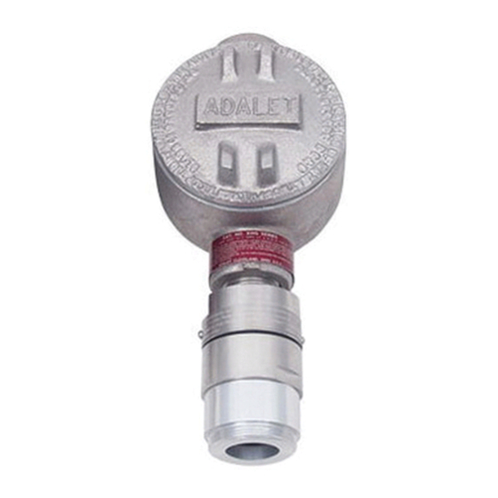
At the mounting site you select, hang or mount the junction box with the detector facing down (see Figure 1). Wiring the CO Detector to a Controller WARNING: Always verify that the power to the controller is off before you make wiring connections. 6 • 61-1004RK/61-0191RK Combustible Gas Detector... - Page 7 Connect the wires to the terminals opposite the detector leads. CAUTION: Leave the shield drain wire insulated and disconnected at the 61-1004RK. You will connect the opposite end of the cable’s drain wire at the controller.
-
Page 8: Startup
Remove the calibration cup from the detector. You may leave the sample tubing connected to the calibration cup for convenience. 10. Store the components of the calibration kit in a safe and convenient place. 8 • 61-1004RK/61-0191RK Combustible Gas Detector... -
Page 9: Maintenance
NOTE: If the reading is not within ± 20% of the gas concentration, calibrate the detector as described in “Calibration” on page 11. Turn the on/off knob clockwise to close the regulator. 10. Unscrew the regulator from the calibration cylinder and remove the sample tubing from the regulator. 61-1004RK/61-0191RK Combustible Gas Detector • 9... -
Page 10: Troubleshooting
Some applications may require a more frequent calibration schedule. Replacing the CO Detector Turn off the controller. Turn off power to the controller. Remove the junction box cover. 10 • 61-1004RK/61-0191RK Combustible Gas Detector... -
Page 11: Calibration Frequency
Assembling the Calibration Kit Screw the calibration cup onto the detector. Use the sample tubing to connect the regulator to the calibration cup. Place the controller into its calibration program or disable external alarms. 61-1004RK/61-0191RK Combustible Gas Detector • 11... -
Page 12: Setting The Zero Reading
NOTE: If you do not allow the gas reading decrease below the alarm points, then unwanted alarms may occur. Verify that the controller display reading decreases and stabilizes at 0. Store the components of the calibration kit in a safe and convenient place. 61-1004RK/61-0191RK Combustible Gas Detector • 12... -
Page 13: Parts List
Parts List Table 3 lists replacement parts and accessories for the 61-1004RK and 61-0191RK CO detectors. Table 3: Parts List Part Number Description 18-0400RK-01 Junction box with spacers 61-0191RK-02 0 to 5,000 ppm CO infrared detector 61-0191RK-03 0 to 5% volume CO...
Need help?
Do you have a question about the 61-1004RK and is the answer not in the manual?
Questions and answers