
Related Manuals for RKI Instruments 65-2380


Summary of Contents for RKI Instruments 65-2380
- Page 1 65-2380 Molecular Property Spectrometer Combustible Gas Detector Operator’s Manual Part Number: 71-0595 Revision: P2 Released: 10/14/22 RKI Instruments, Inc. www.rkiinstruments.com...
- Page 2 Frequency of calibration depends upon the type of use you have and the sensor types. For most applications, typical calibration frequencies are between 6 and 12 months but can be more often or less often based on your usage. 2 • 65-2380 Molecular Property Spectrometer...
- Page 3 Product Warranty RKI Instruments, Inc. warrants gas alarm equipment sold by us to be free from defects in materials, workmanship, and performance for a period of one year from date of shipment from RKI Instruments, Inc. Any parts found defective within that period will be repaired or replaced, at our option, free of charge.
-
Page 4: Table Of Contents
Parts List ............21 4 • 65-2380 Molecular Property Spectrometer... -
Page 5: Overview
Overview This manual describes the 65-2380 MPS combustible gas detector. This manual also describes how to install, start up, maintain, and calibrate the detector when used with a gas monitoring controller. A parts list at the end of this manual lists replacement parts and accessories for the combustible gas detector. -
Page 6: Applications
Dead Bands • All other gases: 5% LEL WARNING: When using the 65-2380, you must follow the instructions and warnings in this manual to assure proper and safe operation of the 65-2380 and to minimize the risk of personal injury. Be sure to maintain and periodically calibrate the 65- 2380 as described in this manual. -
Page 7: Description
Description The 65-2380 combustible gas transmitter utilizes a Molecular Property Spectrometer (MPS) sensor. The MPS sensor is immune to poisons, can be used in high humidity, and does not require calibration as often as catalytic combustible sensors. It also responds accurately to 14 different combustible gases. -
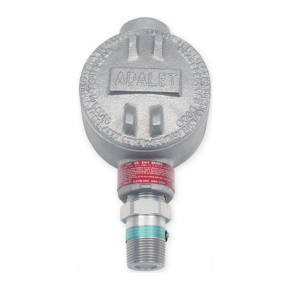
Page 8: Mps Detector
MPS Detector The MPS LEL detector is made up of the MPS combustible gas LEL detector housed and encapsulated in a pipe nipple. The pipe nipple has 3/4 NPT threads on each end and a 1-1/4 inch hex that allows removal or installation of the detector with a wrench. A porous flame arrestor coated with a hydrophobic film that repels liquids is on one end of the detector and allows sample gas to enter the detector. - Page 9 Controller Terminal Strip The controller terminal strip is a three position plug-in style terminal strip located near the top of the amplifier. Use the controller terminal strip to wire the combustible gas transmitter to a controller. Detector Terminal Strip The detector terminal strip is a four position plug-in style terminal strip located below the controller terminal strip.
-
Page 10: Installation
Installation This section describes procedures to mount the combustible gas transmitter in the monitoring environment and wire the transmitter to a controller. Mounting the Combustible Gas Transmitter 1. Select a mounting site that is representative of the monitoring environment. Consider the following when you select the mounting site. -
Page 11: Wiring The Combustible Gas Transmitter
Wiring the Combustible Gas Detector to a Controller WARNING: Always verify that the power to the controller is off before you make wiring connections. 1. Turn off the controller. 2. Turn off or unplug power to the controller. 3. Remove the junction box cover. 4. - Page 12 11. Connect the wires to the applicable detector/transmitter terminal strip at the controller as shown in Figure 11. + 24 VDC 4 - 20 mA In (S) - (DC G round) Cable S hield Controller or J-Box Recording Device Amplifier (Transmitter) Black Green Detector W ires...
-
Page 13: Startup
The procedure below describes applying zero emission air, usually called zero air, using a calibration kit that includes a calibration cup, calibration gas, sample tubing, and a fixed flow regulator with an on/off knob. RKI Instruments, Inc. recommends using a 0.5 LPM (liters per minute) fixed flow regulator. -
Page 14: Maintenance
6. Screw the regulator into the zero air calibration cylinder. 7. Use the calibration kit sample tubing to connect the regulator to the calibration cup. 8. Turn the regulator’s on/off knob counterclockwise to open it. Gas will begin to flow. 9. -
Page 15: Troubleshooting
Troubleshooting The troubleshooting guide describes symptoms, probable causes, and recommended action for problems you may encounter with the combustible gas transmitter. NOTE: This troubleshooting guide describes transmitter problems only. See the controller operator’s manual for problems you may encounter with the controller. Table 3: Troubleshooting the Combustible Gas Transmitter Condition Symptom(s) -
Page 16: Replacing The Mps Lel Sensor
Replacing the MPS LEL Detector 1. Turn off the controller. 2. Turn off or unplug power to the controller. 3. Remove the junction box cover. 4. Remove the detector terminal strip from its socket. 5. Disconnect the detector leads from the detector terminal strip. Note the position of the color- coded leads as you remove them. - Page 17 Replacing the Amplifier 1. Turn off the controller. 2. Turn off or unplug power to the controller. 3. Remove the junction box cover. 4. Unplug the detector terminal strip and controller terminal strip from their sockets. You may leave the wires connected to the terminal strips. 5.
-
Page 18: Calibration Frequency
Although there is no particular calibration frequency that is correct for all applications, a calibration frequency of every 6 months is adequate for most MPS combustible gas transmitter applications. Unless experience in a particular application dictates otherwise, RKI Instruments, Inc. recommends a calibration frequency of every 6 months. -
Page 19: Preparing For Calibration
Materials The following items are required for detector calibration: • a CH calibration cylinder (in a background of real air which contains argon and CO • a 0.5 LPM fixed flow regulator with an on/off knob • a calibration cup for the detector •... -
Page 20: Setting The Response Reading
5. Allow the gas to flow for one minute and verify a reading of 100 mV (±2 mV). If necessary, use the zero pot on the amplifier to adjust the reading to 100 mV (±2 mV). 6. Turn the regulator’s on/off knob clockwise to close the regulator. 7. -
Page 21: Parts List
61-0230 MPS LEL detector 65-2380 MPS transmitter (includes detector, junction box, and amplifier) 71-0595 65-2380 Combustible Gas Detector Operator’s Manual (this document) 81-1051RK Regulator with gauge and knob, 0.5 LPM, for 103 liter calibration cylinders (cylinders with internal threads) 81-1103RK...
Need help?
Do you have a question about the 65-2380 and is the answer not in the manual?
Questions and answers