Vega VEGAWAVE 63 Operating Instructions Manual
Vibrating level switch with tube extension for powders
Hide thumbs
Also See for VEGAWAVE 63:
- Operating instructions manual (40 pages) ,
- Operating instructions manual (36 pages) ,
- Operating instructions manual (36 pages)

Related Manuals for Vega VEGAWAVE 63


Summary of Contents for Vega VEGAWAVE 63
- Page 1 Operating Instructions Vibrating level switch with tube extension for powders VEGAWAVE 63 - two-wire Document ID: 32260...
-
Page 2: Table Of Contents
Rectify faults ........................26 Exchanging the electronics module ................27 How to proceed if a repair is needed ................28 Dismount Dismounting steps......................29 Disposal ......................... 29 Supplement Technical data ........................ 30 Dimensions ........................33 VEGAWAVE 63 • - two-wire... - Page 3 Instructions manuals for accessories and replacement parts Tip: To ensure reliable setup and operation of your VEGAWAVE 63, we of- fer accessories and replacement parts. The corresponding documen- tations are: • 32357 - External housing - VEGAWAVE •...
-
Page 4: About This Document
Action This arrow indicates a single action. Sequence of actions Numbers set in front indicate successive steps in a procedure. Battery disposal This symbol indicates special information about the disposal of bat- teries and accumulators. VEGAWAVE 63 • - two-wire... -
Page 5: For Your Safety
During work on and with the device the required personal protective equipment must always be worn. Appropriate use The VEGAWAVE 63 is a sensor for point level detection. You can find detailed information about the area of application in chapter "Product description". Operational reliability is ensured only if the instrument is properly used according to the specifications in the operating instructions manual as well as possible supplementary instructions. -
Page 6: Safety Label On The Instrument
This device fulfills the legal requirements of the applicable EC guide- lines. By attaching the CE mark, VEGA provides a confirmation of successful testing. You can find the CE conformity declaration in the download area of "www.vega.com". SIL conformity VEGAWAVE 63 meets the requirements to the functional safety ac- cording to IEC 61508. Further information is available in the Safety Manual "VEGAWAVE series 60". Safety instructions for Ex areas Please note the Ex-specific safety information for installation and op- eration in Ex areas. These safety instructions are part of the operating instructions manual and come with the Ex-approved instruments. -
Page 7: Product Description
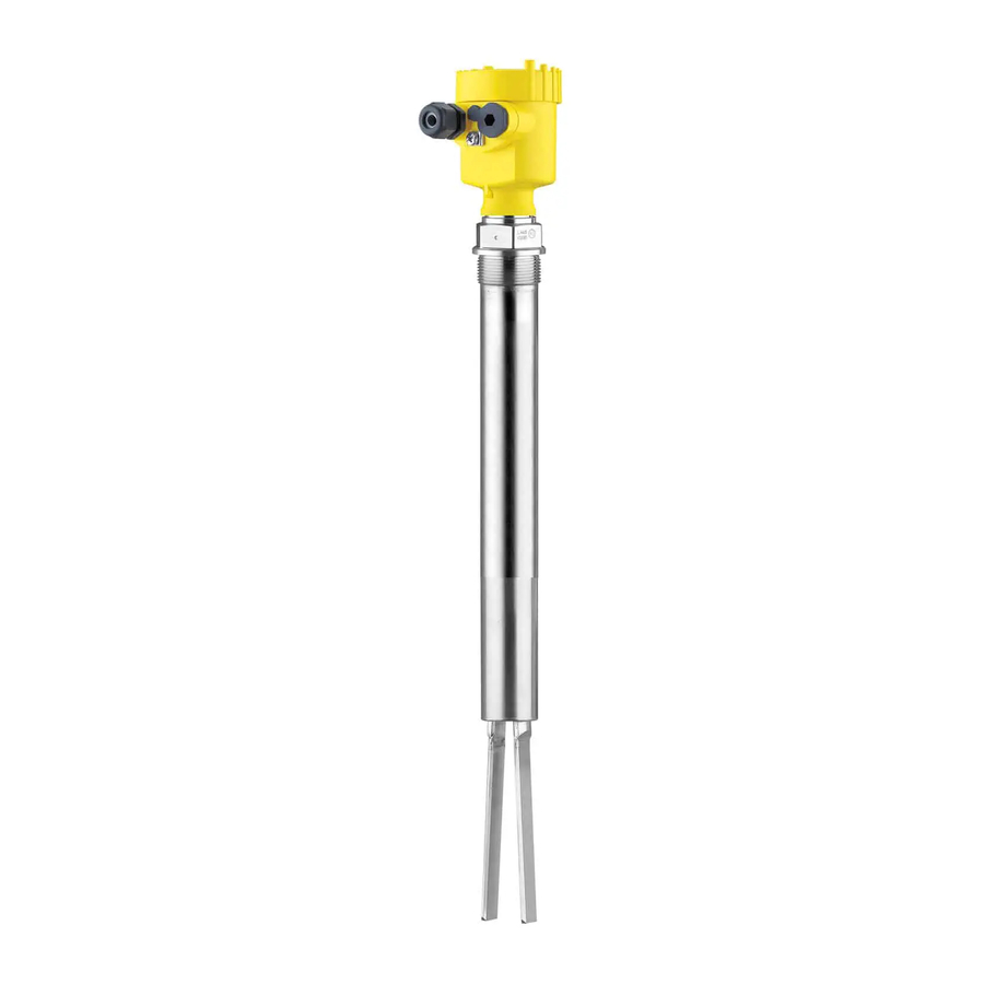
Constituent parts The VEGAWAVE 63 consists of the components: • Housing cover • Housing with electronics • Process fitting with tuning fork Fig. 1: VEGAWAVE 63 - with plastic housing Housing cover Housing with electronics 3 Process fitting Type label The type label contains the most important data for identification and use of the instrument: •... -
Page 8: Principle Of Operation
Principle of operation Application area VEGAWAVE 63 is a point level sensor with tuning fork for point level detection. It is designed for industrial use in all areas of process technology and is preferably used for bulk solids. -
Page 9: Storage And Transport
Not exposed to corrosive media • Protected against solar radiation • Avoiding mechanical shock and vibration • Storage and transport temperature see chapter "Supplement - Storage and transport temperature Technical data - Ambient conditions" • Relative humidity 20 … 85 % VEGAWAVE 63 • - two-wire... -
Page 10: Mounting
You can find the specifications in chapter "Technical data" and on the nameplate. In general, VEGAWAVE 63 can be installed in any position. The instru- Switching point ment only has to be mounted in such a way that the vibrating element is at the height of the desired switching point. -
Page 11: Mounting Instructions
Due to the effects of agitators, equipment vibration or similar, the level switch can be subjected to strong lateral forces. For this reason, do not use an overly long extension tube for VEGAWAVE 63, but check if you can mount a short level switch on the side of the vessel in horizontal position. - Page 12 The tuning fork must be mounted in a way that takes the arrangement of the filling and emptying apertures into account. To compensate measurement errors caused by the material cone in cylindrical vessels, the sensor must be mounted at a distance of d/6 from the vessel wall. Fig. 4: Filling and emptying centred VEGAWAVE 63 • - two-wire...
- Page 13 Fig. 5: Filling in the centre, emptying laterally VEGAWAVE 63 Discharge opening Filling opening To make sure the tuning fork of VEGAWAVE 63 generates as little Product flow resistance as possible to product flow, mount the sensor so that the surfaces are parallel to the product movement. VEGAWAVE 63 • - two-wire...
- Page 14 Marking with screwed version 2 Direction of flow Baffle protection against In applications such as grit chambers or settling basins for coarse falling rocks sediments, the vibrating element must be protected against damage with a suitable baffle. This baffle must be manufactured by you. > 125 mm (> 5") Fig. 7: Baffle for protection against mechanical damage VEGAWAVE 63 • - two-wire...
-
Page 15: Connecting To Power Supply
Voltage supply Take note of the general installation regulations. As a rule, connect VEGAWAVE 63 to vessel ground (PA), or in case of plastic vessels, to the next ground potential. On the side of the instrument housing there is a ground terminal between the cable entries. This connection serves to drain off electrostatic charges. In Ex applications, the instal-... -
Page 16: Wiring Plan, Single Chamber Housing
10. If necessary, carry out a fresh adjustment 11. Screw the housing cover back on The electrical connection is finished. Wiring plan, single chamber housing The following illustrations apply to the non-Ex as well as to the Ex-d version. VEGAWAVE 63 • - two-wire... - Page 17 For further information see the "Technical data" in the "Supplement". The wiring example is applicable for all suitable signal conditioning instruments. If the mode switch of VEGAWAVE 63 is correctly set to "max.", the control lamp on VEGAWAVE 63 lights. • red - with submerged vibrating element • green - with uncovered vibrating element Take note of the operating instructions manual of the signal condition- ing instrument.
-
Page 18: Wiring Plan - Version Ip 66/Ip 68, 1 Bar
Voltage supply Wiring plan - version IP 66/IP 68, 1 bar Wire assignment, con- nection cable Fig. 11: Wire assignment, connection cable brown (+) and blue (-) to power supply or to the processing system Shielding VEGAWAVE 63 • - two-wire... -
Page 19: Setup
Note: As a rule, always set the mode with mode switch (2) before starting the setup of VEGAWAVE 63 . If the instrument is used in conjunction with a signal conditioning instrument, always set the mode switch (2) on VEGAWAVE 63 to max. mode. -
Page 20: Function Chart
(1) It is already preset and must only be modified in special cases. By default, the potentiometer of VEGAWAVE 63 is set to the right stop (> 0.02 g/cm³ or 0.0008 lbs/in³). In case of very light-weight solids, turn the potentiometer to the left stop (> 0.008 g/cm³ or 0.0003 lbs/ in³). - Page 21 The following chart provides an overview of the switching conditions depending on the adjusted mode of the signal conditioning instru- ment and the level. Note: Keep in mind that the mode switch of VEGAWAVE 63 must be always set to "max.". Mode on the Level...
-
Page 22: Recurring Test And Function Test (Sil)
2 Dismounting of the sensor and immersion in the original medium You can dismount the sensor for test purposes and check its proper functioning by immersing it in the original product. VEGAWAVE 63 • - two-wire... - Page 23 Push the test key for > 2 seconds with a suitable object (screwdriver, pen, etc.). When the VEGAWAVE 63 is connected to a processing system or an SPLC, you have to interrupt the connection cable to the sensor for > 2 seconds.
- Page 24 0.6 s 2. Empty approx. energized currentless energized signal 8 mA (approx. 1.5 s) 3. Full signal approx. currentless energized energized 16 mA (approx. 1.5 s) Starting time of the voltage supply VEGAWAVE 63 • - two-wire...
- Page 25 Note: When used in measuring chains according to IEC 61508, mode B is not permitted. Test assessment (SPLC) Test passed • Interference signal (< 3.6 mA) ≥ 400 ms • Uncovered (approx. 8 mA) ≥ 1 s • Covered (approx. 16 mA) ≥ 1 s Test not passed • Interference signal (< 3.6 mA) < 400 ms / ≥ 750 ms • Uncovered (approx. 8 mA) < 1 s / ≥ 2 s • Covered (approx. 16 mA) < 1 s / ≥ 2 s VEGAWAVE 63 • - two-wire...
-
Page 26: Maintenance And Fault Rectification
24 hour service hotline Should these measures not be successful, please call in urgent cases the VEGA service hotline under the phone no. +49 1805 858550. The hotline is manned 7 days a week round-the-clock. Since we offer this service worldwide, the support is only available in the English language. The service is free, only standard call charges are incurred. -
Page 27: Exchanging The Electronics Module
6. Pull out the old electronics module 7. Compare the new electronics module with the old one. The type label of the electronics module must correspond to that of the old electronics module. This applies particularly to instruments used in hazardous areas. VEGAWAVE 63 • - two-wire... -
Page 28: How To Proceed If A Repair Is Needed
Clean the instrument and pack it damage-proof • Attach the completed form and, if need be, also a safety data sheet outside on the packaging • Please contact the agency serving you to get the address for the return shipment. You can find the agency on our home page www.vega.com. VEGAWAVE 63 • - two-wire... -
Page 29: Dismount
These may be used only for privately used products according to the WEEE directive. Correct disposal avoids negative effects on humans and the environ- ment and ensures recycling of useful raw materials. Materials: see chapter "Technical data" If you have no way to dispose of the old instrument properly, please contact us concerning return and disposal. VEGAWAVE 63 • - two-wire... -
Page 30: Supplement
Sensor length (L) 0.3 … 6 m (0.984 … 19.69 ft) Max. lateral load 290 Nm, max. 600 N (214 lbf ft, max. 135 lbf) Fig. 48: Max. lateral load alongside fork side (narrow fork side) VEGAWAVE 63 • - two-wire... - Page 31 Fig. 49: Ambient temperature - Process temperature Process temperature Ambient temperature Temperature range with temperature adapter Product density Ʋ Standard > 0.02 g/cm³ (0.0007 lbs/in³) Ʋ adjustable > 0.008 g/cm³ (0.0003 lbs/in³) Granular size max. 10 mm (0.4 in) VEGAWAVE 63 • - two-wire...
- Page 32 Protection rating Ʋ Plastic housing IP 66/IP 67 (NEMA 4X) Ʋ Aluminium and stainless steel stand- IP 66/IP 68 (0.2 bar), NEMA 6P Depending on the version M12 x 1, according to ISO 4400, Harting, 7/8" FF. A suitable cable is the prerequisite for maintaining the protection rating. VEGAWAVE 63 • - two-wire...
-
Page 33: Dimensions
Approvals Instruments with approvals can have different technical specifications depending on the version. For that reason the associated approval documents of these instruments have to be carefully noted. They are part of the delivery or can be downloaded under www.vega.com via "VEGA Tools" and "Instrument search" as well as via "Downloads" and "Approvals". Dimensions Housing in protection IP 66/IP 67 and IP 66/IP 68; 0.2 bar... - Page 34 9 Supplement G1½ ø 43 mm (1.69") Fig. 52: VEGAWAVE 63, threaded version G1½ A (DIN ISO 228/1) Sensor length, see chapter "Technical data" VEGAWAVE 63 • - two-wire...
- Page 35 9 Supplement ø 34 mm (1.34") Fig. 53: Temperature adapter VEGAWAVE 63 • - two-wire...
- Page 36 Les lignes de produits VEGA sont globalement protégées par des droits de propriété intellec- tuelle. Pour plus d'informations, on pourra se référer au site www.vega.com. VEGA lineas de productos están protegidas por los derechos en el campo de la propiedad indus- trial. Para mayor información revise la pagina web www.vega.com.
- Page 37 Notes VEGAWAVE 63 • - two-wire...
- Page 38 Notes VEGAWAVE 63 • - two-wire...
- Page 39 Notes VEGAWAVE 63 • - two-wire...
- Page 40 Subject to change without prior notice © VEGA Grieshaber KG, Schiltach/Germany 2014 VEGA Grieshaber KG Phone +49 7836 50-0 Am Hohenstein 113...
Need help?
Do you have a question about the VEGAWAVE 63 and is the answer not in the manual?
Questions and answers