Vega VEGAWAVE 63 Operating Instructions Manual
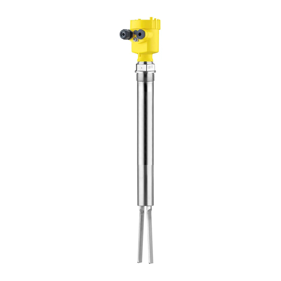
Vibrating level switch with tube extension for powders namur
Hide thumbs
Also See for VEGAWAVE 63:
- Operating instructions manual (40 pages) ,
- Operating instructions manual (36 pages) ,
- Operating instructions manual (40 pages)

Related Manuals for Vega VEGAWAVE 63


Summary of Contents for Vega VEGAWAVE 63
- Page 1 Operating Instructions Vibrating level switch with tube extension for powders VEGAWAVE 63 NAMUR Document ID: 32259...
-
Page 2: Table Of Contents
Exchanging the electronics module ................24 How to proceed if a repair is necessary ................25 Dismount..........................27 Dismounting steps......................27 Disposal ......................... 27 Supplement ..........................28 Technical data ........................ 28 Dimensions ........................32 Industrial property rights ....................35 VEGAWAVE 63 • NAMUR... - Page 3 Contents Trademark ........................35 Safety instructions for Ex areas Take note of the Ex specific safety instructions for Ex applications. These instructions are attached as documents to each instrument with Ex approval and are part of the operating instructions. Editing status: 2018-11-22 VEGAWAVE 63 • NAMUR...
-
Page 4: About This Document
Symbols used Document ID This symbol on the front page of this instruction refers to the Docu- ment ID. By entering the Document ID on www.vega.com you will reach the document download. Information, tip, note This symbol indicates helpful additional information. -
Page 5: For Your Safety
During work on and with the device, the required personal protective equipment must always be worn. Appropriate use The VEGAWAVE 63 is a sensor for point level detection. You can find detailed information about the area of application in chapter "Product description". Operational reliability is ensured only if the instrument is properly used according to the specifications in the operating instructions manual as well as possible supplementary instructions. -
Page 6: Safety Label On The Instrument
You can find the EU conformity declaration on our website under www.vega.com/downloads. SIL conformity VEGAWAVE 63 meets the requirements to the functional safety ac- cording to IEC 61508. Further information is available in the Safety Manual "VEGAWAVE series 60". Installation and operation in the USA and Canada This information is only valid for USA and Canada. -
Page 7: Product Description
– Safety Manual "Functional safety (SIL)" (optional) – Supplementary instructions manual "Plug connector for level sensors" (optional) – Ex-specific "Safety instructions" (with Ex versions) – If necessary, further certificates Constituent parts The VEGAWAVE 63 consists of the components: • Housing lid • Housing with electronics •... -
Page 8: Principle Of Operation
Principle of operation Application area VEGAWAVE 63 is a point level sensor with tuning fork for point level detection. It is designed for industrial use in all areas of process technology and is preferably used for bulk solids. -
Page 9: Storage And Transport
Technical data - Ambient conditions" • Relative humidity 20 … 85 % Lifting and carrying With instrument weights of more than 18 kg (39.68 lbs) suitable and approved equipment must be used for lifting and carrying. VEGAWAVE 63 • NAMUR... -
Page 10: Mounting
DIN/EN/IEC/ANSI/ISA/UL/CSA 61010-1. Switching point In general, VEGAWAVE 63 can be installed in any position. The instru- ment only has to be mounted in such a way that the vibrating element is at the height of the desired switching point. -
Page 11: Mounting Instructions
Due to the effects of agitators, equipment vibration or similar, the level switch can be subjected to strong lateral forces. For this reason, do not use an overly long extension tube for VEGAWAVE 63, but check if you can mount a short level switch on the side of the vessel in horizontal position. - Page 12 The tuning fork must be mounted in a way that takes the arrangement of the filling and emptying apertures into account. To compensate measurement errors caused by the material cone in cylindrical vessels, the sensor must be mounted at a distance of d/6 from the vessel wall. VEGAWAVE 63 • NAMUR...
- Page 13 4 Mounting Fig. 4: Filling and emptying centred Fig. 5: Filling in the centre, emptying laterally VEGAWAVE 63 Discharge opening Filling opening VEGAWAVE 63 • NAMUR...
- Page 14 4 Mounting To make sure the tuning fork of VEGAWAVE 63 generates as little Product flow resistance as possible to product flow, mount the sensor so that the surfaces are parallel to the product movement. Fig. 6: Flow orientation of the tuning fork Marking with screwed version 2 Direction of flow Baffle protection against In applications such as grit chambers or settling basins for coarse...
-
Page 15: Connecting To Power Supply
Voltage supply Connect the voltage supply according to the following diagrams. Take note of the general installation regulations. As a rule, connect VEGA- WAVE 63 to vessel ground (PA), or in case of plastic vessels, to the next ground potential. On the side of the instrument housing there is a ground terminal between the cable entries. -
Page 16: Wiring Plan, Single Chamber Housing
10. If necessary, carry out a fresh adjustment 11. Screw the housing lid back on The electrical connection is finished. Wiring plan, single chamber housing The following illustrations apply to the non-Ex as well as to the Ex-d version. VEGAWAVE 63 • NAMUR... - Page 17 In addition to the test key on the electronics module, you can connect an external key to start the test procedure. Connect the key according to the following wiring plan. In shipping condition, terminals 3 and 4 are bridged. For additional information see "Recurring function test". VEGAWAVE 63 • NAMUR...
-
Page 18: Wiring Plan - Version Ip 66/Ip 68, 1 Bar
External simulation key Wiring plan - version IP 66/IP 68, 1 bar Wire assignment, con- nection cable Fig. 12: Wire assignment, connection cable Brown (+) and blue (-) to power supply or to the processing system Shielding VEGAWAVE 63 • NAMUR... -
Page 19: Setup
(1) It is already preset and must only be modified in special cases. By default, the potentiometer of VEGAWAVE 63 is set to the right stop (> 0.02 g/cm³ or 0.0008 lbs/in³). In case of very light-weight solids, turn the potentiometer to the left stop (> 0.008 g/cm³ or 0.0003 lbs/ in³). -
Page 20: Function Table
• dark = Low current ≤ 1.0 mA • yellow (flashing) = Failure ≤ 1.0 mA Function table Level switch VEGAWAVE 63 The following table provides an overview of the switching conditions depending on the set mode and the level. Note: The mode setting on the NAMUR amplifier must be selected in such a way that the switching output takes on safe state in case of failure (I ≤ 1 mA). -
Page 21: Proof Test (Sil)
NAMUR electronics module WE60N. For this purpose, the switching delay must be set to 0.5 s. VEGAWAVE 63 has an inte- grated simulation key. The simulation key is lowered on the electronics module. Push the simulation key for > 2 seconds. - Page 22 ≥ 2.2 mA (1.5 s ±0.5 s) 3. Return to the actual operating con- dition You can carry out the function test with the stated current values also directly with a safety PLC or a process control system. VEGAWAVE 63 • NAMUR...
-
Page 23: Maintenance And Fault Rectification
24 hour service hotline Should these measures not be successful, please call in urgent cases the VEGA service hotline under the phone no. +49 1805 858550. The hotline is manned 7 days a week round-the-clock. Since we offer this service worldwide, the support is only available in the English language. The service is free, only standard call charges are incurred. -
Page 24: Exchanging The Electronics Module
Proceed as follows: 1. Switch off voltage supply 2. Unscrew the housing lid 3. Lift the opening levers of the terminals with a screwdriver 4. Pull the connection cables out of the terminals 5. Loosen the two screws with a screw driver (Torx size T10 or slot VEGAWAVE 63 • NAMUR... -
Page 25: How To Proceed If A Repair Is Necessary
14. Check cable gland on tightness. The seal ring must completely encircle the cable. 15. Screw the housing lid back on The electronics exchange is now finished. How to proceed if a repair is necessary You can find an instrument return form as well as detailed informa- tion about the procedure in the download area of our homepage: www.vega.com. VEGAWAVE 63 • NAMUR... - Page 26 Clean the instrument and pack it damage-proof • Attach the completed form and, if need be, also a safety data sheet outside on the packaging • Please contact the agency serving you to get the address for the return shipment. You can find the agency on our home page www.vega.com. VEGAWAVE 63 • NAMUR...
-
Page 27: Dismount
Pass the instrument directly on to a specialised recycling company and do not use the municipal collecting points. If you have no way to dispose of the old instrument properly, please contact us concerning return and disposal. VEGAWAVE 63 • NAMUR... -
Page 28: Supplement
2000 g/m (21.5 oz/ft) Sensor length (L) 0.3 … 6 m (0.984 … 19.69 ft) Sensor lengths - accuracy ± 2 mm (± 0.079 in) Max. lateral load 290 Nm, max. 600 N (214 lbf ft, max. 135 lbf) VEGAWAVE 63 • NAMUR... - Page 29 Measured variable Limit level of solids Process pressure -1 … 25 bar/-100 … 2500 kPa (-14.5 … 363 psig) VEGAWAVE 63 of 316L -50 … +150 °C (-58 … +302 °F) Process temperature (thread or flange -50 … +250 °C (-58 … +482 °F)
- Page 30 5 m (16.4 ft) Ʋ Max. length 1000 m (3280 ft) Ʋ Min. bending radius 25 mm (0.984 in) with 25 °C (77 °F) Depending on the version M12 x 1, according to ISO 4400, Harting, 7/8" FF. VEGAWAVE 63 • NAMUR...
- Page 31 Instruments with approvals can have different technical specifications depending on the version. For that reason the associated approval documents of these instruments have to be carefully noted. They are part of the delivery or can be downloaded under www.vega.com, "Instrument search (serial number)" as well as in the general download area.
-
Page 32: Dimensions
~ 103 mm (5.91") (4.06") ø 77 mm ø 84 mm (3.03") (3.31") M20x1,5 M20x1,5 M20x1,5 Fig. 34: Housing versions with protection rating IP 66/IP 68 (1 bar) Stainless steel single chamber (precision casting) Aluminium - single chamber VEGAWAVE 63 • NAMUR... - Page 33 9 Supplement G1½ ø 43 mm (1.69") Fig. 35: VEGAWAVE 63, threaded version G1½ (DIN ISO 228/1) Sensor length, see chapter "Technical data" VEGAWAVE 63 • NAMUR...
- Page 34 9 Supplement ø 34 mm (1.34") Fig. 36: Temperature adapter VEGAWAVE 63 • NAMUR...
-
Page 35: Industrial Property Rights
Les lignes de produits VEGA sont globalement protégées par des droits de propriété intellec- tuelle. Pour plus d'informations, on pourra se référer au site www.vega.com. VEGA lineas de productos están protegidas por los derechos en el campo de la propiedad indus- trial. Para mayor información revise la pagina web www.vega.com. - Page 36 Subject to change without prior notice © VEGA Grieshaber KG, Schiltach/Germany 2018 VEGA Grieshaber KG Phone +49 7836 50-0 Am Hohenstein 113...
Need help?
Do you have a question about the VEGAWAVE 63 and is the answer not in the manual?
Questions and answers