Vega VEGACAP 64 Operating Instructions Manual
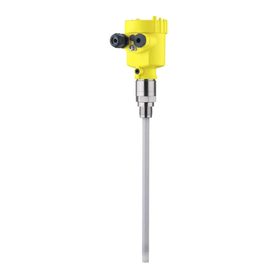
Capacitive rod electrode for level detection. contactless electronic switch
Hide thumbs
Also See for VEGACAP 64:
- Operating instructions manual (40 pages) ,
- Operating instructions manual (36 pages) ,
- Operating instructions manual (36 pages)

Subscribe to Our Youtube Channel
Related Manuals for Vega VEGACAP 64


Summary of Contents for Vega VEGACAP 64
- Page 1 Operating Instructions Capacitive rod electrode for level detection VEGACAP 64 Contactless electronic switch Document ID: 30013...
-
Page 2: Table Of Contents
How to proceed if a repair is necessary ................26 Dismount..........................27 Dismounting steps......................27 Disposal ......................... 27 Supplement ..........................28 Technical data ........................ 28 Dimensions ........................31 Industrial property rights ....................34 Trademark ........................34 VEGACAP 64 • Contactless electronic switch... - Page 3 Contents Editing status: 2020-09-24 VEGACAP 64 • Contactless electronic switch...
-
Page 4: About This Document
Symbols used Document ID This symbol on the front page of this instruction refers to the Docu- ment ID. By entering the Document ID on www.vega.com you will reach the document download. Information, tip, note This symbol indicates helpful additional information. -
Page 5: For Your Safety
During work on and with the device, the required personal protective equipment must always be worn. Appropriate use The VEGACAP 64 is a sensor for point level detection. You can find detailed information about the area of application in chapter " Product description". Operational reliability is ensured only if the instrument is properly used according to the specifications in the operating instructions manual as well as possible supplementary instructions. -
Page 6: Eu Conformity
That is why we have introduced an environment management system with the goal of continuously improving company environmental pro- tection. The environment management system is certified according to DIN EN ISO 14001. Please help us fulfil this obligation by observing the environmental instructions in this manual: • Chapter " Packaging, transport and storage" • Chapter " Disposal" VEGACAP 64 • Contactless electronic switch... -
Page 7: Product Description
Constituent parts The VEGACAP 64 consists of the components: • Process fitting with probe • Housing with electronics • Housing lid Fig. 1: VEGACAP 64, rod version with plastic housing Housing lid Housing with electronics 3 Process fitting VEGACAP 64 • Contactless electronic switch... - Page 8 Alternatively, you can access the data via your smartphone: • Download the VEGA Tools app from the " Apple App Store" or the " Google Play Store" • Scan the DataMatrix code on the type label of the instrument or •...
-
Page 9: Principle Of Operation
3 Product description Principle of operation Application area VEGACAP 64 is a point level sensor for use in non-abrasive liquids and bulk solids. The rod probe is fully insulated and due to its construction is suitable for all viscous and adhesive products. -
Page 10: Packaging, Transport And Storage
Protective cover The protective cover protects the sensor housing against soiling and intense heat from solar radiation. Flanges Screwed flanges are available in different versions according to the following standards: DIN 2501, EN 1092-1, BS 10, ASME B 16.5, JIS B 2210-1984, GOST 12821-80. VEGACAP 64 • Contactless electronic switch... -
Page 11: Mounting
Use the recommended cables (see chapter " Connecting to power supply") and tighten the cable gland. You can give your instrument additional protection against moisture penetration by leading the connection cable downward in front of the cable gland. Rain and condensation water can thus drain off. This VEGACAP 64 • Contactless electronic switch... - Page 12 In the case of instrument housings with self-sealing NPT threads, it is not possible to have the cable entries screwed in at the factory. The free openings for the cable glands are therefore covered with red dust protection caps as transport protection. VEGACAP 64 • Contactless electronic switch...
-
Page 13: Mounting Instructions
Agitators and fluidization Due to the effects of agitators, equipment vibration or similar, the level switch can be subjected to strong lateral forces. For this reason, do not use an overly long electrode for VEGACAP 64, but check if you can mount a short level switch on the side of the vessel in horizontal position. Extreme vibration caused by the system, e.g. due to agitators or turbulence in the vessel from fluidisation, can cause the probe of VEGACAP 64 to vibrate in resonance. - Page 14 Torque with PTFE plated To compensate the material-specific preload loss due to sealing ma- flanges terials, you have to additionally use disc springs for fastening flange screws on PTFE coated flanges. Tighten the screws moderately with the torque stated in the technical data. Depending on the process and ambient conditions, this value can vary. In individual cases you should occasionally check the tightness on site. VEGACAP 64 • Contactless electronic switch...
-
Page 15: Connecting To Power Supply
4. Insert the cable into the sensor through the cable entry 5. Lift the opening levers of the terminals with a screwdriver (see following illustration) 6. Insert the wire ends into the open terminals according to the wir- ing plan VEGACAP 64 • Contactless electronic switch... -
Page 16: Wiring Plan, Single Chamber Housing
Fig. 7: Connection steps 5 and 6 Wiring plan, single chamber housing Housing overview Fig. 8: Material versions, single chamber housing Plastic (not with dust-Ex) Aluminium Stainless steel Filter element for air pressure compensation VEGACAP 64 • Contactless electronic switch... - Page 17 Connection terminals Control lamp Wiring plan We recommend connecting VEGACAP 64 in such a way that the switching circuit is open when there is a level signal, line break or failure (safe state). The contactless electronic switch is always shown in non-operative condition.
- Page 18 5 Connecting to power supply When VEGACAP 64 is used as part of an overfill protection system according to WHG, also note the regulations of the general type ap- proval. Fig. 10: Wiring plan Voltage supply VEGACAP 64 • Contactless electronic switch...
-
Page 19: Setup
Note: As a rule, always set the mode with the mode switch (3) before start- ing setup VEGACAP 64. The switching output will change if you set the mode switch (3) afterwards. This could possibly trigger other con- nected instruments or devices. - Page 20 (1) until the control lamp lights green [lights red]. 6. Note the position of the potentiometer (1). In some cases the lowest range (range 1 = highest sensitivity) is not sufficient to adjust the full switch point. This would make another filling procedure necessary. VEGACAP 64 • Contactless electronic switch...
- Page 21 When the control lamp (6) lights green: continue with the next item. 5. Turn the potentiometer (1) very slowly anticlockwise until the control lamp (6) lights red. The measuring system is now ready for operation. VEGACAP 64 • Contactless electronic switch...
-
Page 22: Function Table
Green Mode max. Overflow protection Switch open Mode min. Dry run protection Switch closed Green Mode min. Dry run protection Switch open Failure of the supply volt- (min./max. mode) Switch open Fault Switch open flashes red VEGACAP 64 • Contactless electronic switch... -
Page 23: Maintenance And Fault Rectification
24 hour service hotline Should these measures not be successful, please call in urgent cases the VEGA service hotline under the phone no. +49 1805 858550. The hotline is manned 7 days a week round-the-clock. Since we offer this service worldwide, the support is only available in the English language. The service is free, only standard call charges are incurred. -
Page 24: Exchange Of The Electronics Module
Depending on the reason for the fault and the measures taken, the fication steps described in chapter " Set up" may have to be carried out again. Exchange of the electronics module In general, all oscillators of series CP60 can be interchanged. VEGACAP 64 • Contactless electronic switch... - Page 25 10. Screw in and tighten the two holding screws with a screwdriver (Torx size T10 or Phillips 4) 11. Insert the wire ends into the open terminals according to the wir- ing plan 12. Press down the opening levers of the terminals, you will hear the terminal spring closing VEGACAP 64 • Contactless electronic switch...
-
Page 26: How To Proceed If A Repair Is Necessary
Clean the instrument and pack it damage-proof • Attach the completed form and, if need be, also a safety data sheet outside on the packaging • Please contact the agency serving you to get the address for the return shipment. You can find the agency on our home page www.vega.com. VEGACAP 64 • Contactless electronic switch... -
Page 27: Dismount
Pass the instrument directly on to a specialised recycling company and do not use the municipal collecting points. If you have no way to dispose of the old instrument properly, please contact us concerning return and disposal. VEGACAP 64 • Contactless electronic switch... -
Page 28: Supplement
Ʋ Rod weight: ø 16 mm (0.63 in) 1100 g/m (12 oz/ft) Sensor length (L) Ʋ Process fitting: thread and flanges 0.15 … 6 m (0.492 … 19.69 ft) Ʋ Process fitting: Flanges - PTFE plated 0.15 … 6 m (0.492 … 19.69 ft) Max. lateral load 10 Nm (7.4 lbf ft) VEGACAP 64 • Contactless electronic switch... - Page 29 -0.4 … 16 bar/-40 … 1600 kPa (-5.8 … 232 psig), de- pending on the process fitting Process temperature VEGACAP 64 of -50 … +150 °C (-58 … +302 °F) 316L Process temperature (thread or flange -50 … +200 °C (-58 … +392 °F) temperature) with temperature adapter (option) Distance from the process fittings to the set switching point. Distance from the process fittings to the set switching point. VEGACAP 64 • Contactless electronic switch...
- Page 30 9 Supplement Process temperature VEGACAP 64 of St -20 … +150 °C (-4 … +302 °F) C22.8 80°C (176°F) 40°C (104°F) 0°C (32°F) -50°C 50°C 100°C 150°C 200°C (-58°F) (122°F) (212°F) (302°F) (392°F) -40°C (-40°F) Fig. 15: Ambient temperature - Process temperature...
-
Page 31: Dimensions
Dimensions The following dimensional drawings represent only an extract of all possible versions. Detailed dimensional drawings can be downloaded at www.vega.com/downloads under " Drawings". VEGACAP 64, housing ~ 69 mm ~ 59 mm ~ 69 mm ~ 116 mm (4.57") - Page 32 9 Supplement A, G 1 A, G 1 ø16mm ( ") Fig. 17: VEGACAP 64, threaded version G1 (ISO 228 T1) Sensor length, see chapter "Technical data" L1 active length VEGACAP 64 • Contactless electronic switch...
- Page 33 9 Supplement ø 40 mm (1.58") Fig. 18: Temperature adapter VEGACAP 64 • Contactless electronic switch...
-
Page 34: Industrial Property Rights
Les lignes de produits VEGA sont globalement protégées par des droits de propriété intellec- tuelle. Pour plus d'informations, on pourra se référer au site www.vega.com. VEGA lineas de productos están protegidas por los derechos en el campo de la propiedad indus- trial. Para mayor información revise la pagina web www.vega.com. - Page 35 Notes VEGACAP 64 • Contactless electronic switch...
- Page 36 Subject to change without prior notice © VEGA Grieshaber KG, Schiltach/Germany 2020 VEGA Grieshaber KG Phone +49 7836 50-0 Am Hohenstein 113...
Need help?
Do you have a question about the VEGACAP 64 and is the answer not in the manual?
Questions and answers