Advertisement

Description
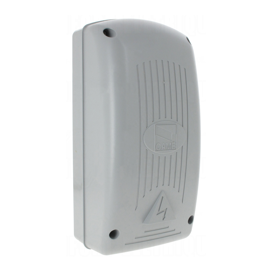
Four-outdoor radio modules for the control of automations and accessories.
Stand-by consumption is 60 mA.


Main components

- Radio code memorisation buttons
- Connector for coding TAM/TFM transmitters via cable
- LED indicator for storage
- DIP selector for functions OUT3 / 4
- AF card socket
- Connection terminal block
- Power supply terminal block
- Antenna connection terminal block
Technical data


Preliminary checks
Check that the fixing point is solid and is in an area protected from impact
Installation

Electrical Connections

- Power supply: 12 V DC or 24 V AC/DC.
- Operators and/or accessories to be controlled:
Max voltage 230 V, with resistive load.
Max absorption 0.5 A.
Selecting Functions

Selectable functions for OUT 3 and OUT 4 only.
Hold to Run 
The action of the relay lasts as long as the button on the transmitter is held down.
Fixed 3" timed monostable 
After releasing the button on the transmitter, the relay action lasts 3 seconds.
Bistable (switch) 
Repeatedly pressing the transmitter button enables and disables the relay continuously.
Fixed 5' timed monostable 
After pressing the button on the transmitter, the relay action lasts 5 minutes.
Activating radio control


THIS MODULE MUST NOT BE CONNECTED  .
.
- Press and hold key 1 = OUT1
![]() and press the key of the transmitter to associate
and press the key of the transmitter to associate ![]() . The LED will remain lit to indicate that memorisation has taken place
. The LED will remain lit to indicate that memorisation has taken place ![]() .
. - Perform the same procedure for the other outputs (2 = OUT2, 3 = OUT3 and 4 = OUT4
![]() .
.
Duplication code
only for TAM/TFM

- Check that the bridge on the transmitter strip is disabled
![]() .
. - Connect the transmitter to the receiver, with the 119RIR211 cable (not supplied)
![]() .
. - Hold down the key (for the desired output) on the card at the same time as the key on the transmitter (associated to the target output) for about two seconds
![]() . The LED will show that memorisation has taken place
. The LED will show that memorisation has taken place ![]() .
. - Repeat the same procedure for each transmitter.
- For the operating test, remove the wire from the receiver and the transmitter.
Legislative references
This product complies with the applicable standards in force at the time of manufacturing.
RED - CAME S.p. A. declares that the product described in this manual complies with Directive 2014/53/EU and the Radio Equipment Regulations 2017.
The full EC declaration of conformity and UK Conformity Assessed (UKCA) marking information can be found at www.came.com.
Decommissioning and disposal.
Dispose of the packaging and the device at the end of its life cycle responsibly, in compliance with the laws in force in the country where the product is used. The recyclable components are marked with a symbol and the material's ID marker.
THE DATA PRESENTED IN THIS MANUAL MAY BE SUBJECT TO CHANGE, AT ANY TIME, AND WITHOUT NOTICE. MEASUREMENTS, UNLESS OTHERWISE STATED, ARE IN MILLIMETERS.

Documents / Resources
References
Download manual
Here you can download full pdf version of manual, it may contain additional safety instructions, warranty information, FCC rules, etc.
Advertisement
 and press the key of the transmitter to associate
  . The LED will remain lit to indicate that memorisation has taken place
  .
. .
. .
. .
. . The LED will show that memorisation has taken place
  .
.


Need help?
Do you have a question about the RBE4N and is the answer not in the manual?
Questions and answers