
Subscribe to Our Youtube Channel
Related Manuals for Planet LRE-104


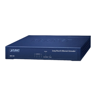
Summary of Contents for Planet LRE-104
- Page 1 4-Port 10/100TX + 1-Port UTP/BNC Long Reach Ethernet Extender LRE-104 User’s Manual...
- Page 2 PLANET has made every effort to ensure that this User’s Manual is accurate; PLANET disclaims liability for any inaccuracies or omissions that may have occurred.
- Page 3 Do not dispose of WEEE as unsorted municipal waste and have to collect such WEEE separately. Revision PLANET 4-Port 10/100TX + 1-Port UTP/BNC Long Reach Ethernet Extender User’s Manual Model: LRE-104 Revision: 1.0 (Feb.2023)
-
Page 4: Table Of Contents
4.1 Wall-mount Installation ..............11 5. Applications ..................12 5.1 Point-to-Point Application -- LAN to LAN Connection ......12 5.2 LRE-104 for IP Surveillance Application .......... 14 6. Performance Table ................15 7. Troubleshooting .................. 17 8. FAQs ....................18... -
Page 5: Package Contents
1. Package Contents Thank you for purchasing PLANET LRE-104 4-Port 10/100TX + 1-Port UTP/BNC Long Reach Ethernet Extender. In the following sections, the term “Ethernet Extender” means the LRE-104. Open the box of the Ethernet Extender and carefully unpack it. The box should... -
Page 6: Hardware Introduction
The rich diagnostic LEDs on the front panel can provide the operating status of individual port and whole system. System Color Function Lit: Power ON Green Off: Power OFF Lit: Indicates that the LRE-104 is functioned as a Master. Master Green Off: Indicates that the LRE-104 is functioned as a Slave. -
Page 7: Rear View
Indicates the TP port is actively sending or receiving Blink: data. Off: Indicates that the TP port is link-down. 2.3 Rear View LRE-104 Rear Panel Long Reach Only either of the interfaces is allowed to be selected. Master Slave... -
Page 8: Power Information
2.4 Power Information The LRE-104 requires 12V DC, 1A power input, which conforms to the bundled AC adapter. Should you have the issue of power connection, contact your local sales representative. -
Page 9: Product Specifications
3. Product Specifications LRE-104 Product Hardware Specifications 4 x 10/100BASE-TX RJ45 copper port, Connector auto-negotiation/auto-MDI/MDI-X Cabling Cat5e UTP or above LAN Ethernet Maximum Interface 100 meters distance Maximum 1522 bytes frame size Connector 1 x RJ45 copper port 1 x BNC female port ... - Page 10 Power Requirement 12V DC, 1A external power Power: Green LAN: Green, 10/100Mbps LNK/ACT LED Indicators Long Reach: Green, LNK Master: Green Compatible Long Reach LRE-101 Extender LRE-101C Standards Conformance IEEE 802.3/802.3u Ethernet standard compliant IEEE 802.3x Full-duplex flow control Standards Compliance IEEE 802.1q Tag VLAN Transparent, Multicast pass-through Regulatory Compliance...
-
Page 11: Installations
Step 2: Screw two screws on the wall. 90.00 Ø7mm Ø2mm Step 3: Hang the LRE-104 on the screws from the wall. Step 4: Repeat Chapter 2.4 Power Information on power supply to the LRE-104. Before mounting the device to the wall, please check the loca-... -
Page 12: Applications
Point to Point Application 5V DC adapter 12V DC adapter Phone wire Up to 1200m Cat5E UTP Up to 700m LRE-101 Master Switch LRE-104 Slave 5V DC adapter 12V DC adapter Ethernet over Coaxial LRE-101C Master Switch LRE-104 Slave Up to 2000m... - Page 13 1. [LAN1] Set the LRE-101/LRE-101C in LAN 1 to be in the Master mode from the DIP switch 2. [LAN2] Set the LRE-104 in LAN 2 to be in the Slave mode from the DIP switch 3. Power on the Master and Slave at both sides by connecting its power source.
-
Page 14: Lre-104 For Ip Surveillance Application
Refer to the following procedure to set up an IP surveillance system with many pairs of the LRE-104: 1. Set the LRE-101C to be the Master and LRE-104 to be the Slave mode from the DIP switch on the rear panel. -
Page 15: Performance Table
6. Performance Table Phone wire (RJ11) Phone wire Upstream / Downstream Unit: Mbps Distance (meter) 1000 1200 UTP Cable (RJ45) RJ45 Cable Upstream / Downstream Unit: Mbps Distance (meter) 800 (Max.) Coaxial Cable (BNC) BNC Cable Upstream / Downstream Unit: Mbps Distance (meter) 1000 1200... - Page 16 The actual data rate will vary in the quality of the UTP cables or phone wire and environmental factors.
-
Page 17: Troubleshooting
SYMPTOM: LNK LED does not light up after wire is connected to the Long Reach port. CHECKPOINT: Please note you must use one LRE-104 in Master mode and the other LRE-104 in Slave mode to make connection. SYMPTOM: TP LED does not light after cable is connected to the port. -
Page 18: Faqs
8. FAQs Q1: What is the best distance for LRE-104? A1: In order to guarantee the stability and better quality of network, we suggest the distance should not exceed 700m (Cat.5 UTP) and 1200m (Phone wire). -
Page 19: Customer Support
9. Customer Support Thank you for purchasing PLANET products. You can browse our online FAQ resource and User’s Manual on PLANET Web site first to check if it could solve your issue. If you need more support information, please contact PLANET switch support team.
Need help?
Do you have a question about the LRE-104 and is the answer not in the manual?
Questions and answers