Panasonic KX-NS300 Installation Manual
Hybrid ip-pbx
Hide thumbs
Also See for KX-NS300:
- Pc programming manual (752 pages) ,
- Basic specification (471 pages) ,
- User manual (388 pages)
Table of Contents
Advertisement
Quick Links
ที อี เอ็ น พี เ อบี เ อ็ ก ซ์ / TeN PABX
51/500 หมู ่ บ ้ า นเสนา 88 ซอย 9 ซอยนวลจั น ทร์ 17 แขวงนวลจั น ทร์
เขตบึ ง กุ ่ ม กรุ ง เทพฯ 10240
ปรึ ก ษา / สอบถาม / แจ้ ง ซ่ อ ม: Hotline: 089-1454237 E-mail:
tawintra.kawintra@gmail.com
www.tenpabx.com
Thank you for purchasing this Panasonic product.
Please read this manual carefully before using this product and save this manual for future use.
In particular, be sure to read "1.1 For Your Safety (Page 14)" before using this product.
KX-NS300: PFMPR Software File Version 001.00000 or later
Installation Manual
Hybrid IP-PBX
KX-NS300
Model No.
Advertisement
Table of Contents
Troubleshooting

Related Manuals for Panasonic KX-NS300


Summary of Contents for Panasonic KX-NS300
- Page 1 Please read this manual carefully before using this product and save this manual for future use. In particular, be sure to read "1.1 For Your Safety (Page 14)" before using this product. KX-NS300: PFMPR Software File Version 001.00000 or later...
- Page 2 System Components System Components System Components for KX-NS300 Category Model No. Description Main Unit KX-NS300 Main Unit Activation Key Codes KX-NSE101 Activation Key for Mobile Extension for 1 User (1 Mobile User) KX-NSE105 Activation Key for Mobile Extension for 5 Users (5...
- Page 3 System Components Category Model No. Description KX-NSN002 Activation Key for QSIG Network (QSIG Network) KX-NSU002 Activation Key for Two-way Recording Control (Two-way REC Control) KX-NSU003 Activation Key for Message Backup (Message Backup) KX-NSU102 2-Channel Unified Messaging Activation Key (2 UM Port) KX-NSU104 4-Channel Unified Messaging Activation Key (4 UM...
- Page 4 System Components Category Model No. Description KX-NSA301 Activation Key for CA ACD Monitor for 1 ICD Supervisor (CA Supervisor) KX-NSA401 Activation Key for CA Operator Console (CA Console) KX-NSA901 Activation Key for CA Network Plug-in for 1 User (CA Network 1 user) KX-NSA905 Activation Key for CA Network Plug-in for 5 Users (CA Network 5 users)
- Page 5 16-port Digital Extension Card (DLC16) KX-NS5173 8-Port SLT Card (MCSLC8) KX-NS5174 16-Port SLT Card (MCSLC16) Equipment Compatibility for Main Unit KX-NS300 The PBX supports the following equipment: Cell Stations DECT • DECT 2-Channel Cell Stations Unit Using DLC Card for DECT Portable Station (KX-TDA0155CE) •...
- Page 6 Equipment Compatibility for Expansion Unit KX-NS320 You can connect Expansion Unit KX-NS320s to expand the usage of legacy terminals and trunks. If a expansion unit KX-NS320 is connected to a KX-NS300, the following equipment is also supported. Cell Stations DECT •...
- Page 7 Note • Some optional hardware, software, and features are not available in some countries/areas. Please consult your certified Panasonic dealer for more information. • In this manual, the suffix of each model number (e.g., KX-NS300BX) is omitted unless necessary. List of Abbreviations CA ®...
- Page 8 Introduction Introduction This Installation Manual is designed to serve as an overall technical reference for the Panasonic IP-PBX, KX-NS300, It provides instructions for installing the hardware, and programming the PBX using Web Maintenance Console. This PBX can also be programmed by using PT. Refer to the PT Programming Manual for more information.
- Page 9 The Bluetooth word mark and logos are registered trademarks owned by Bluetooth SIG, Inc., and any use ® of such marks by Panasonic Corporation is under license. • Microsoft, Outlook, Internet Explorer, Windows and Windows Vista are either registered trademarks or trademarks of Microsoft Corporation in the United States and/or other countries.
-
Page 10: Table Of Contents
SD Memory XS Card (KX-NS3134), SD Memory S Card (KX-NS3135), SD Memory M Card (KX-NS3136) .......................101 4.3.3 DSP S Card (KX-NS5110) ...................102 4.3.4 LCOT6 in KX-NS300 (installed by default) ..............104 4.3.5 DLC2 in KX-NS300 (installed by default) ..............107 4.3.6 MCSLC16 in KX-NS300 (installed by default) ..............108 4.3.7... - Page 11 Table of Contents 4.3.10 RMT card in KX-NS300 (KX-TDA0196) ...............115 Virtual Cards ........................116 Physical Trunk and Extension Cards ................118 4.5.1 LCOT6 Card (KX-NS5180) ...................118 4.5.2 PRI30/E1 Card (KX-NS5290CE) ..................119 4.5.3 DHLC4 Card (KX-NS5170) ..................122 4.5.4 DLC8 Card (KX-NS5171) .....................123 4.5.5 DLC16 Card (KX-NS5172) ...................124...
- Page 12 Connection ........................257 7.1.3 Operation ........................258 7.1.4 Error Messages ......................259 7.1.5 Restarting the KX-NS300 .....................261 7.1.6 Troubleshooting by Error Log ..................263 8 Networking Information ...............265 Information about Using an IP Network ..............266 8.1.1 Using a VoIP Network with the PBX ................266 8.1.2...
-
Page 13: Safety Precautions
Section 1 Safety Precautions This section provides important information intended to prevent personal injury and property damage. Installation Manual... -
Page 14: For Your Safety
1.1 For Your Safety 1.1 For Your Safety To prevent personal injury and/or damage to property, be sure to observe the following safety precautions. The following symbols classify and describe the level of hazard and injury caused when this unit is operated or handled improperly. - Page 15 1.1 For Your Safety WARNING For All Telephone Equipment • Do not install the product in any other way than described in relevant manuals. • Do not install the product in a place exposed to rain or moisture, or a place where water, oil, or other liquids can drip or splash onto on the product.
- Page 16 • Do not attempt to repair the power cord or plug. If the power cord or plug is damaged or frayed, contact an authorised Panasonic Factory Service Centre for a replacement. • Do not leave the slot open if an option service card is not installed after removing a dummy cover plate.
- Page 17 Once you have started the PBX, if you unplug the PBX, do not initialise it again as described in "System Initialisation Procedure". Otherwise, your programmed data will be cleared. To restart the PBX, refer to "7.1.5 Restarting the KX-NS300". •...
- Page 18 1.1 For Your Safety • The plug of power supply cordset is used as the main disconnect device. Ensure that the AC outlet is located near the equipment and is easily accessible. • Slots and openings in the front, back and bottom of the cabinet are provided for ventilation; to protect it from overheating, these openings must not be blocked or covered.
- Page 19 Contact your telephone company. If all SLTs operate properly, there may be a problem with your PBX. Do not reconnect the PBX to the trunks until it has been serviced by an authorised Panasonic Factory Service Centre. Installation Manual...
-
Page 20: Important Safety Instructions
1.2 Important Safety Instructions 1.2 Important Safety Instructions When using your telephone equipment, basic safety precautions should always be followed to reduce the risk of fire, electric shock and injury to persons, including the following: • Do not use the product near water, for example, near a bathtub, wash bowl, kitchen sink, or laundry tub, in a wet basement, or near a swimming pool. -
Page 21: Precautions
1.3 Precautions 1.3 Precautions For users in the European Union only Information for Users on Collection and Disposal of Old Equipment and used Batteries These symbols on the products, packaging, and/or accompanying documents mean that used electrical and electronic products and batteries should not be mixed with general household waste. -
Page 22: Data Security
1.4 Data Security 1.4 Data Security In order to use the PBX safely and correctly, the Security Requirements below must be observed. Failure to do so may result in: • Loss, leakage, falsification or theft of user information. • Illegal use of the PBX by a third party. •... -
Page 23: System Outline
Section 2 System Outline This section provides general information on the PBX, including the system capacity and specifications. Installation Manual... -
Page 24: Basic System Construction
Stacking Expansion Unit KX-NS320 Up to 3 Expansion Unit KX-NS320s can be connected to a KX-NS300 to expand the usage of legacy terminals and trunks. A KX-NS320 connected to a KX-NS300 functions as a expansion unit and will be controlled by the KX-NS300. - Page 25 2.1.1 System Configurations An H.323 QSIG network is preferable if strict resource separation between sites is necessary. In a QSIG network, resources are not available to extension users of other PBXs without explicit programming. For details about programming the H.323 QSIG network, refer to "5.5 Programming an H.323 QSIG Network".
-
Page 26: System Connection Diagram
Expansion Unit* Trunk (Telephone Company Lines) Analogue/PRI Expansion Unit* External Sensor Fax Machine Doorphone & Door Opener BGM/Music On Hold (MOH) Pager/ Amplifier Speaker ITSP: Internet Telephony Service Provider DCE: Data Circuit Terminating Equipment CA: Communication Assistant KX-NS300 KX-NS320 Installation Manual... - Page 27 IP-PT IP Softphone, CA Client PC Router Mountable Equipment ITSP (e.g., ADSL Network Modem) Trunk Adaptor Trunk Adaptor ISDN PRI Line E1 Line (Digital Trunk) (Digital Trunk) Telephone Company Some DPT is not available for this connection. Installation Manual KX-NS300...
-
Page 28: Optional Equipment
DPT* DPT* Some DPT is not available for this connection. KX-NS320 2.2 Optional Equipment 2.2.1 Optional Equipment KX-NS300 Model No. Model Name Description KX-NS5110 VoIP DSP Card (S Type) (DSP S) A DSP card is a digital signal processor card with... - Page 29 2.2.1 Optional Equipment Model No. Model Name Description KX-NS3134 SD Memory Card (XS Type) (SD A combination card including Memory XS) • Memory with maximum of 40 hours Voice Mail recording time. • Memory with Maximum of 40,000 SMDR data and 10,000 Hotel Billing Data •...
- Page 30 2.2.1 Optional Equipment Model No. Model Name Description KX-NS5130 3-port expansion Master Card A stacking card to be installed in a KX-NS300. (EXP-M) Up to 3 Expansion Unit KX-NS320 can be connected. KX-NS5170 4-Port Super Hybrid Extension 4-port digital hybrid extension card for DPTs,...
- Page 31 2.2.1 Optional Equipment KX-NS320 Model No. Model Name Description KX-NS5162 Doorphone Interface Card (DPH2) 2-port doorphone card for 2 doorphone, door opener and 2 external sensor KX-NS5180 6-port Analogue Trunk Card 6 analogue trunk ports with Caller ID (FSK/FSK (LCOT6) with Call Waiting Caller ID [Visual Caller ID]/ DTMF).
-
Page 32: Specifications
2.3.1 General Description 2.3 Specifications 2.3.1 General Description KX-NS300 Main CPU Cortex A8 600 MHz Power Input 100 V AC to 130 V AC: 2.2 A/200 V AC to 240 V AC: 1.3 A; 50 Hz/60 Hz Power Consumption (when fully... - Page 33 2.3.1 General Description Weight (when fully mounted) Under 4.5 kg Except the 19-inch rack mounting equipment KX-NS320 Main CPU Cortex A8 300 MHz Power Input 100 V AC to 130 V AC: 2.2 A/200 V AC to 240 V AC: 1.3 A; 50 Hz/60 Hz Power Consumption (when fully 110 W...
-
Page 34: Characteristics
2.3.2 Characteristics 2.3.2 Characteristics KX-NS300 Terminal Equipment Loop Limit • SLT: 600 W including set • Doorphone: 20 W 15 000 W minimum Minimum Leakage Resistance Maximum Number of Extension 1 for SLT Instruments per Line Ring Voltage 75 Vrms at 20 Hz/25 Hz depending on the Ringing Load... -
Page 35: System Capacity
2.3.3 System Capacity 2.3.3 System Capacity Type and Maximum Number of Slots The PBX supports the following type and number of slots. KX-NS300 Mother Board Slot Type Maximum Number Physical Slot DSP Card Slot SD Card Slot EXP-M Card Slot... - Page 36 2.3.3 System Capacity Main Unit Front View Inside View (The top cover is removed.) Front cover plate for the EXP-M Slot Front cover plates for Trunk/Doorphone Card Slots Front cover plates for the Extension Card Slots Extension Card Slot Trunk/Doorphone Card Slot EXP-M Card Slot SD Card Slot DSP Card Slot...
- Page 37 2.3.3 System Capacity Expansion Unit Front View Inside View (The top cover is removed.) Front cover plates for Trunk/Doorphone Card Slots Front cover plates for the Extension Card Slots Extension Card Slot Trunk/Doorphone Card Slot SD Card Slot (not available) Installation Manual...
- Page 38 2.3.3 System Capacity Virtual Slots of the Mother Board Example: V-SIPEXT8 V-IPEXT8 V-SIPGW4 V-UTEXT8 V-IPCS4 V-IPGW4 Virtual Slots Mother Board Installation Manual...
- Page 39 Note • Any card that exceeds the capacity of the PBX will be ignored. • When the PBX starts up with an invalid configuration, some cards will be ignored. For KX-NS300 Physical Slot Slot type Card Name Maximum Number Pre-installed...
- Page 40 2.3.3 System Capacity Cards Installed in Virtual Slots Card type Card Name Maximum Number Virtual Trunk Card V-IPGW4 V-SIPGW4 Virtual Extension Card V-IPEXT8 V-SIPEXT8 V-UTEXT8 Virtual IP-CS Card V-IPCS4 If you want to use IP-Extension, IP-Trunk, IP-CS or Unified Messaging system, you need to install Activation key KX-NSF990.
- Page 41 2.3.3 System Capacity Trunk Option Card Installing Restrictions KX-NS300 2nd Slot LCOT6 PRI30/E1 DPH2 LCOT6 — — ü PRI30/E1 — — ü 1st Slot DPH2 — ü ü This installation combination is not available due to software restrictions. KX-NS320 2nd Slot...
- Page 42 2.3.3 System Capacity Maximum Trunks, Extensions, VMs, PFT ports and MOHs/Pagers The PBX supports the following number of trunks and extensions. KX-NS300 KX-NS300 KX-NS300 KX-NS300 KX-NS300 Trunk (Pre-Installed (Maximum) KX-NS320 KX-NS320s KX-NS320s Total Number of Trunks Trunk (Physical Trunk Card)
- Page 43 2.3.3 System Capacity KX-NS300 KX-NS300 KX-NS300 KX-NS300 KX-NS300 Trunk (Pre-Installed (Maximum) KX-NS320 KX-NS320s KX-NS320s SIP Phone KX-UT Series SIP DECT Total Number of CS DPT-CS (2ch) DPT-CS (8ch) IP-CS SIP-CS Total Number of PS Total Number of Doorphone Doorphone Door Opener...
- Page 44 2.3.3 System Capacity DSP Resources DSP card provides digital signal processor (DSP) resources, and the PBX uses the resources to perform various PBX operations. The following illustration shows the concept of DSP resource usage. More complex situations may require additional resources, and in some cases the amount of DSP resources required may be less than expected.
- Page 45 Expandable Resources with Expansion Unit The following table shows the types of resources that are available when an expansion unit used with a KX-NS300. Notice When Expansion Units are used with a c, all IP-PTs are registered to the KX-NS300. Installation Manual...
- Page 46 PT-interface CS ü ü IP-CS/IP-PT/KX-UT Series SIP Phone/SIP-CS – Doorphone ü IP Softphone – Activation Key Any Activation key – IP terminals, except for KX-NT265 (software version 2.00 or later only), are registered and controlled by the KX-NS300. Installation Manual...
-
Page 47: Information About The Activation Keys
Section 3 Information about the Activation Keys This section provides information on activation keys, including how to obtain activation keys. Installation Manual... -
Page 48: Information About The Activation Keys
3.1 Information about the Activation Keys Activation keys are required to use IP trunks and IP telephones on a private IP network with a KX-NS300. Also, to upgrade the software to use enhanced features, the corresponding activation keys for that feature are required. - Page 49 3.1.1 Type and Maximum Number of Activation Keys IP Telephone Capacity Maximum IP Model No. Activation Key Type Description Telephones KX-NSM201 1 IPSoftphone/IP PT Allows the use of 1 IP-PT/IP softphone/KX-UT series SIP phone. KX-NSM205 5 IPSoftphone/IP PT Allows the use of 5 IP-PTs/IP softphones/KX-UT series SIP Total 128 IP-PTs/IP phones.
- Page 50 3.1.1 Type and Maximum Number of Activation Keys Feature Guide References for Related Features of Activation Keys QSIG Network • 4.2.1.4 Common Extension Numbering for 2 PBXs • 4.2.2.2 Common Extension Numbering for Multiple PBXs • 4.2.5 QSIG Enhanced Features •...
- Page 51 3.1.1 Type and Maximum Number of Activation Keys Unified Messaging System (Mailbox) Model No. Activation Key Type Description Maximum Mailboxes KX-NSU201 UM/E-mail 1 User Allows the use of an e-mail (IMAP4) client and e-mail notification (voice) for 1 user. KX-NSU205 UM/E-mail 5 Users Allows the use of an e-mail (IMAP4) client and e-mail...
- Page 52 3.1.1 Type and Maximum Number of Activation Keys Feature Guide References for Related Features of Activation Keys 3.2.2.30 Two-way Record/Two-way Transfer Cellular Phone Extension Maximum Cellular Model No. Activation Key Type Description Phone Extensions KX-NSE101 1 Mobile User Allows the use of 1 cellular phone extension.
- Page 53 3.1.1 Type and Maximum Number of Activation Keys Activation Maximum Activation Model No. Description Key Type Keys KX-NSA201 CA Pro 1 Allows the use of CA Client Pro for 1 user. user KX-NSA205 CA Pro 5 Allows the use of CA Client Pro for 5 users. users KX-NSA210 CA Pro 10...
- Page 54 3.1.1 Type and Maximum Number of Activation Keys Activation Key Activated Features CA Basic-Express No Limit IP Proprietary Telephone (ch) 4 IP-PTs/KX-UT series SIP phones UM Port (ch) 2 Unified Messaging ports Example: Preinstalled Activation Keys in the Mother Board Preinstalled activation keys for free trial The following activation keys are preinstalled on the mother board for the 60-days free trial.
- Page 55 3.1.1 Type and Maximum Number of Activation Keys Example: Desired Item: 10 IP-PTs 5 IP softphones Required Activation Key: KX-NSM510, KX-NSM205 Desired Item: 4 SIP trunks Required Activation Key: KX-NSM104 V-IPEXT8 V-SIPGW4 Desired Item: V-UTEXT8 V-IPGW4 4 H.323 trunks Required Activation Key: Virtual Slots KX-NSM104 Desired Item:...
-
Page 56: Activation Key Code And Key Management System
3.1.2 Activation Key Code and Key Management System 3.1.2 Activation Key Code and Key Management System To obtain additional activation keys, you need to purchase the appropriate activation key codes and access the Key Management System. You can download the activation keys as an activation key file from the Key Management System. -
Page 57: Using Cti Applications
3.1.3 Using CTI Applications 3.1.3 Using CTI Applications To use CTI applications with the KX-NS300, KX-NSF101 (CTI interface) is required. One KX-NSF101 supports one CTI application. However, Communication Assistant (CA) Server does not require KX-NSF101. In the example below, one KX-NSF101 is required for using one CTI application. - Page 58 3.1.3 Using CTI Applications Example 3 Panasonic CSTA Multiplexer CTI Application Server Single CSTA Connection CTI Application Server CTI Application Server CA Server Note • Up to 4 CTI application servers can be used at the same time when using a CSTA multiplexer.
-
Page 59: Installation
Section 4 Installation This section describes the procedures to install the PBX. Detailed instructions for planning the installation site, installing the main unit and optional service cards, and cabling of peripheral equipment are provided. Further information on peripheral equipment installation is included. -
Page 60: Before Installation
Be sure to comply with all applicable laws, regulations, and guidelines. Notice Panasonic assumes no responsibility for injuries or property damage resulting from failures arising out of improper installation or operation inconsistent with this documentation. Safety Installation Instructions WARNING... - Page 61 4.1.1 Before Installation • On or near computers, or other office equipment, as well as microwave ovens or air conditioners. (It is preferable not to install the system in the same room as the above equipment.) • Within 1.8 m of radios and televisions. (Both the PBX and PTs should be at least 1.8 m away from such devices.) Do not perform the following: •...
-
Page 62: Installation Of The Pbx
4.2.1 Unpacking 4.2 Installation of the PBX 4.2.1 Unpacking KX-NS300 Unpack the box and check the items below: • Main unit • CD-ROM(s) • AC power cord • Hook clip • Screw x 3 (For Wall Mounting) • Washer x 3 (For Wall Mounting) The number of included CD-ROMs varies according to the country/area. -
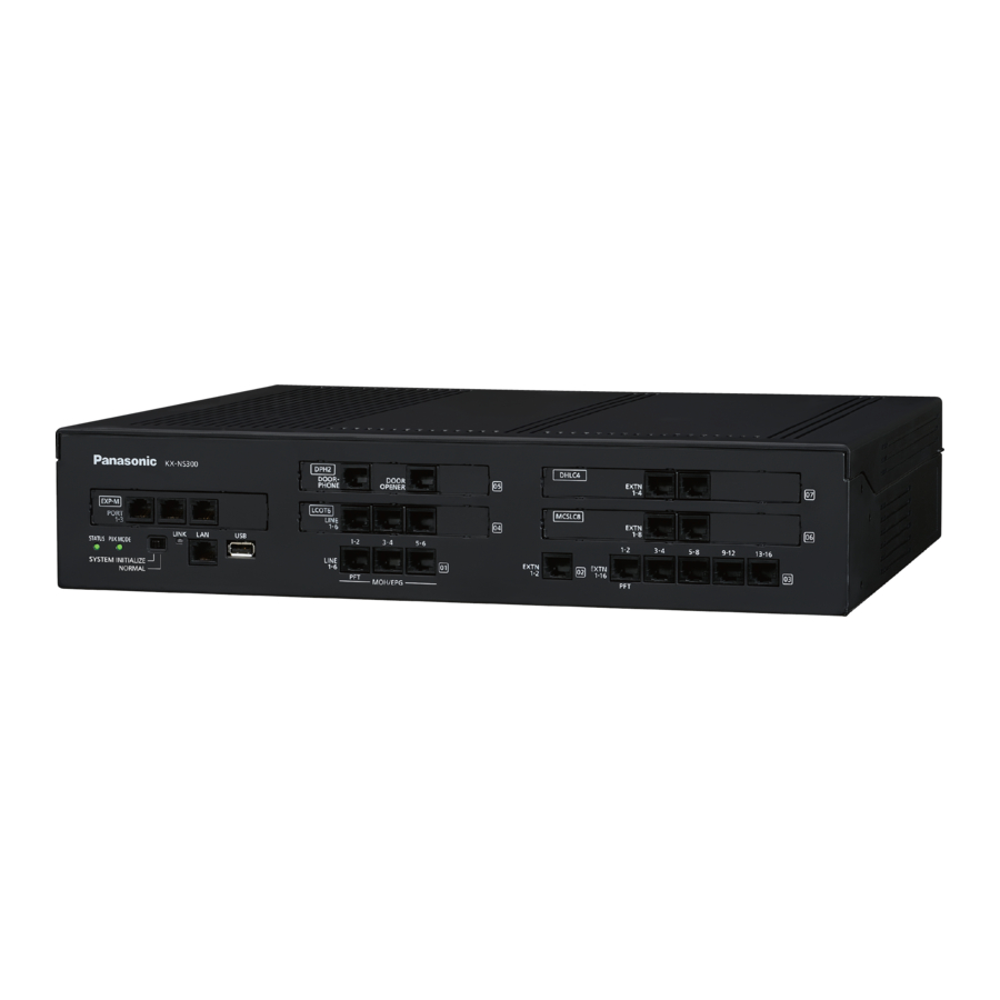
Page 63: Names And Locations
4.2.2 Names and Locations 4.2.2 Names and Locations KX-NS300 Front Back/Inside STATUS Indicator PBX MODE indicator (Unused) System Mode Switch LAN Port USB Port LCOT Ports DPT Port SLT Ports EXP-M slot Trunk/Doorphone Free Slot Extension Free Slot Top Cover... - Page 64 4.2.2 Names and Locations KX-NS320 Front Back/Inside STATUS Indicator EXT-S Port PFT Port SLT Slot Trunk/Doorphone Free Slot Extension Free Slot Top Cover Sub Board Main Board FG Terminal AC Inlet Power Switch External Battery Battery Switch Installation Manual...
-
Page 65: Opening/Closing The Top Cover
4.2.3 Opening/Closing the Top Cover 4.2.3 Opening/Closing the Top Cover Opening the Top Cover KX-NS300/KX-NS320 CAUTION When opening the top cover, the power switch must be turned off. Confirm that the power switch is turned off and pull the power cable. - Page 66 4.2.3 Opening/Closing the Top Cover Slide the top cover then lift it off. Closing the Top Cover Place the top cover onto the PBX. Then slide the top cover until it closes properly. Turn the screws clockwise to tighten. CAUTION For safety reasons, close the top cover and tighten the screws before operating the PBX.
-
Page 67: Frame Earth Connection
4.2.4 Frame Earth Connection 4.2.4 Frame Earth Connection KX-NS300/KX-NS320 Loosen the screw. Insert an earthing wire (user-supplied). Tighten the screw. Connect the earthing wire to earth. Screw Earthing wire To earth WARNING • Proper earthing (connection to earth) is very important to reduce the risk to the user of electrocution or to protect the PBX from the bad effects of external noise in the case of a lightning strike. -
Page 68: Installing/Removing The Optional Service Cards
4.2.5 Installing/Removing the Optional Service Cards 4.2.5 Installing/Removing the Optional Service Cards CAUTION • Before touching the product (PBX, cards, etc.), discharge static electricity by touching ground or wearing an earthing strap. Failure to do so may cause the PBX to malfunction due to static electricity. •... - Page 69 4.2.5 Installing/Removing the Optional Service Cards Installing a DSP Card in a DSP Card Slot Place the front end of the card under the hook, and then lower the rear end of the card so that the holes of the card are aligned with the screw holes. Installation Manual...
- Page 70 4.2.5 Installing/Removing the Optional Service Cards Insert the screws into the holes on the card, and tighten the screws to secure the card. Screws Removing a DSP Card Installed in the DSP Card Slot Loosen and remove the screws. Screws Installation Manual...
- Page 71 Installing an Optional Service Card in the Free Slot In the Main Unit KX-NS300 and Expansion Unit KX-NS320, there are Free slot for Trunk/Doorphone cards and Free slot for Extension cards. In Free slot for Trunk/Doorphone card, you can install the following cards: LCOT6, PRI30/E1 Doorphone card.
- Page 72 4.2.5 Installing/Removing the Optional Service Cards Remove the front cover plate for the Free slot. Dummy Cover Plate Installation Manual...
- Page 73 4.2.5 Installing/Removing the Optional Service Cards Position the card in the open slot, making sure that the tabs on the both sides of the card fit into place. Then, holding the card firmly in place, lower the rear end so that the holes of the card are aligned with the screw holes.
- Page 74 4.2.5 Installing/Removing the Optional Service Cards Insert the spacers into the holes on the card, and tighten the spacers to secure the card. Spacer Note When using larger sized cards with smaller sized cards, install the larger sized cards in the bottom. Connect cables to appropriate ports of the card.
- Page 75 4.2.5 Installing/Removing the Optional Service Cards Removing Optional Service Card from the Free Slot Loosen and remove the spacers. Spacer Holding the rear end of the card, pull the card in the direction of the arrows. Installation Manual...
- Page 76 4.2.5 Installing/Removing the Optional Service Cards Installing the EXP-M Card in the EXP-M Card slot Remove the front cover plate for the EXP-M card. Dummy Cover Plate Installation Manual...
- Page 77 4.2.5 Installing/Removing the Optional Service Cards Position the card in the EXP-M card slot, making sure that the tabs on the both sides of the card fit into place. Then, holding the card firmly in place, lower the rear end so that the holes of the card are aligned with the screw holes.
- Page 78 4.2.5 Installing/Removing the Optional Service Cards Insert the screws into the holes on the card, and tighten the screws to secure the card. Screws Connect cables to the appropriate ports of the card. For details about pin assignments, refer to the appropriate section in "4.6.1 EXP-M Card (KX-NS5130)".
- Page 79 4.2.5 Installing/Removing the Optional Service Cards Holding the rear end of the card, pull the card in the direction of the arrows. Installation Manual...
- Page 80 4.2.5 Installing/Removing the Optional Service Cards Slot covers Only remove the dummy cover plates when you are planning to install an optional service card. If you do not install an optional service card, insert a slot cover included with the option service card, as shown in the following procedure.
- Page 81 4.2.5 Installing/Removing the Optional Service Cards To remove a slot cover Remove the top cover. Refer to "Opening the Top Cover" in "4.2.3 Opening/Closing the Top Cover". From the inside, push the tab of the slot cover to the right and push out the left edge of the slot cover. Installation Manual...
-
Page 82: Installing/Removing The Sd Memory Card
To prevent data leakage, render the SD Memory Card physically unusable before disposal. Notice • Use only a Panasonic optional SD Memory Card. • The SD Memory Card must be inserted in the SD Memory Card slot of the mother board before startup. - Page 83 (For details, refer to "4.3.2 SD Memory XS Card (KX-NS3134), SD Memory S Card (KX-NS3135), SD Memory M Card (KX-NS3136)".) Start the PBX as described in "System Initialisation Procedure" in "4.13 Starting the KX-NS300". Perform Easy Setup Wizard. (For details, refer to "5.4.1 Easy Setup Wizard".) Restore the system prompts backed up in step 2.
- Page 84 4.2.6 Installing/Removing the SD Memory Card Removing the SD Memory Card Remove the SD Memory Card installed in the slot on the mother board. Installation Manual...
-
Page 85: Types Of Connectors
MCSLC16 (KX-NS5174) Note • Pin assignments for RJ45 connectors differ depending on the card. Refer to the "Pin Assignments" section of each card in "Section 4 Installation". KX-TDA0158 connecting to KX-NS300 CS1 (RJ45) DHLC4/DLC8/DLC16 card (RJ45) PIN No. Signal Name Port No. - Page 86 4.2.7 Types of Connectors • When a wrong connection is made, satisfactory performance of the CS cannot be guaranteed. Check the connection of CS and the PBX using the Web Maintenance Console. For information about how to view CS information using the Web Maintenance Console, refer to "4.1.2 Status—Equipment Status—CS Information"...
-
Page 87: Attaching A Ferrite Core
4.2.8 Attaching a Ferrite Core 4.2.8 Attaching a Ferrite Core A ferrite core must be attached when an RJ45 connector is connected to the EXP-M card or EXP-S card. For the EXP-M/EXP-S Cards Wrap the cable once around the ferrite core, then close the case of the ferrite core. Attach the ferrite core 5 cm away from the connector. -
Page 88: 19-Inch Rack Mounting
4.2.9 19-inch Rack Mounting 4.2.9 19-inch Rack Mounting WARNING • Be careful not to drop any components. Dropping components may damage them or cause an injury. • When mounting the PBX on a 19-inch rack, only use the 19-inch rack mounting equipment (attachment bracket, screws) included with the PBX. -
Page 89: Wall Mounting
4.2.10 Wall Mounting 4.2.10 Wall Mounting The PBX can be mounted on a concrete wall using the optional wall mounting kit. WARNING • Make sure that the wall that the unit will be attached to is strong enough to support approximately 4 times the weight of the unit. - Page 90 4.2.10 Wall Mounting Mounting on a Wooden Wall The included screws may be used when mounting the main unit on a wooden wall. Measure the actual space as indicated below to mark the 3 screw positions on the wall. 200 mm 290 mm 100 mm Install the screws and washers (included) to the wall.
- Page 91 4.2.10 Wall Mounting Mounting on a Concrete The included screws may be used when mounting the main unit on a concrete wall. User-supplied anchor plugs are also necessary. Measure the actual space as indicated below to mark the 3 screw positions on the wall. 200 mm 290 mm 100 mm...
- Page 92 4.2.10 Wall Mounting Hook the main unit on the screw heads. Installation Manual...
-
Page 93: Surge Protector Installation
4.2.11 Surge Protector Installation 4.2.11 Surge Protector Installation CAUTION Performing surge protection is essential. Make sure to follow the instructions in this section. Overview A massive electrical surge can be caused if lightning strikes a telephone cable 10 m above ground, or if a telephone line comes into contact with a power line. - Page 94 4.2.11 Surge Protector Installation Outside Installation (Main Building) Surge Protector Trunk (Another Building) Trunk Extn. Terminal Board Surge Extn. Protector Extn. Extn. Earth Extn.: Extension Line If you install an extension outside of the building, the following precautions are recommended: Install the extension wire underground.
- Page 95 4.2.11 Surge Protector Installation Connect the earth rod to the surge protector using an earthing wire with a cross-sectional area of at least 1.3 mm Bury the earth rod near the protector. The earthing wire should be as short as possible. The earthing wire should run straight to the earth rod.
-
Page 96: Backup Battery Connection
4.2.12 Backup Battery Connection 4.2.12 Backup Battery Connection The backup batteries and Back-up Battery Cable provide a backup power supply to allow full use of the PBX in the event of a power failure. In case of power failure, the backup batteries automatically maintain the power to the PBX without interruption. - Page 97 4.2.12 Backup Battery Connection Connect the Back-up Battery Cable to a set of 3 identical backup batteries. Battery Connector Cover Battery Connector Back-up Battery Cable Fuse Battery Switch Black Backup Batteries (VRLA 12 V DC x 3) Installation Manual...
-
Page 98: The Mother Board And Expansion Cards
SD Memory Card (refer to "4.3.2 SD Memory XS Card (KX-NS3134), SD Memory S Card (KX-NS3135), SD Memory M Card (KX-NS3136)") • Remote Card refer to "4.3.10 RMT card in KX-NS300 (KX-TDA0196)") EXP-M Card Slot LAN Port DSP Card Slot... - Page 99 For details about connecting peripherals, refer to "4.10 Connection of Peripherals". • For details about System Mode Switch, refer to "4.13 Starting the KX-NS300". WARNING A lithium battery is used in the mother board. There is a risk of explosion if the battery is replaced with the incorrect type.
-
Page 100: Mother Board - Kx-Ns320
4.3.1 Mother Board Indication Colour Description 10BASE-T/ LINK Green Link status indication 100BASE-TX • OFF: Off-line • ON: Linked normally • Flashing: In communication 4.3.1.2 Mother Board - KX-NS320 Function The mother board of expansion unit KX-NS320 is the pre-installed processing board with the EXP-S card, PFT card, MCSLC16 card. -
Page 101: Sd Memory Xs Card (Kx-Ns3134), Sd Memory S Card (Kx-Ns3135), Sd Memory M Card (Kx-Ns3136)
4.3.2 SD Memory XS Card (KX-NS3134), SD Memory S Card (KX-NS3135), SD Memory M Card (KX-NS3136) 4.3.2 SD Memory XS Card (KX-NS3134), SD Memory S Card (KX-NS3135), SD Memory M Card (KX-NS3136) Function SD Memory XS, S, M If you install one of the SD Memory card, you can expand the number Card: of SMDR data and Hotel Billing data. -
Page 102: Dsp S Card (Kx-Ns5110)
4.3.3 DSP S Card (KX-NS5110) 4.3.3 DSP S Card (KX-NS5110) Function A DSP card is a digital signal processor card with DSP resources that can be used for VoIP calls, conferences, the Unified Messaging feature, and the DISA/OGM feature. The DSP card is compliant with ITU-T G.729A and G.711 codec methods. - Page 103 4.3.3 DSP S Card (KX-NS5110) IP Address Information 1 IP address must be assigned to each DSP card, depending on the type of DSP card. You can assign an IP address to the DSP card during Easy Setup Wizard or through system programming. For details about Easy Setup Wizard, refer to "5.4.1 Easy Setup Wizard".
-
Page 104: Lcot6 In Kx-Ns300 (Installed By Default)
4.3.4 LCOT6 in KX-NS300 (installed by default) 4.3.4 LCOT6 in KX-NS300 (installed by default) Function • 6 analogue trunk ports with Caller ID (FSK/FSK with Call Waiting Caller ID [Visual Caller ID]/DTMF). • 6 MOH/External Pager port. • 2 ports are power failure transfer (PFT) ports. (Port 1 and Port 2) Note •... - Page 105 4.3.4 LCOT6 in KX-NS300 (installed by default) External Pager Port 1 = Pager 1 Port 2 = Pager 2 Port 3 = Pager 3 Port 4 = Pager 4 Port 5 = Pager 5 Port 6 = Pager 6 Port Type Setting by Web Maintenance Console...
- Page 106 4.3.4 LCOT6 in KX-NS300 (installed by default) For MOH/Pager Use Signal Name Function M/P1 A Music/Pager port 1 M/P2 A Music/Pager port 1 Reserved – Reserved – Reserved – Reserved – M/P1 B Music/Pager port 2 M/P2 B Music/Pager port 2...
-
Page 107: Dlc2 In Kx-Ns300 (Installed By Default)
4.3.5 DLC2 in KX-NS300 (installed by default) 4.3.5 DLC2 in KX-NS300 (installed by default) Function • 2 digital extension port for DPT and PT-interface CSs. To Extension Pin Assignments For DLC port Signal Name Function D1 A Data port 1 (Low) -
Page 108: Mcslc16 In Kx-Ns300 (Installed By Default)
4.3.6 MCSLC16 in KX-NS300 (installed by default) 4.3.6 MCSLC16 in KX-NS300 (installed by default) Function • 16 extension ports for SLT with Caller ID (FSK), Message Waiting Lamp control, and 2 power failure transfer (PFT) ports. Maximum power output of 90 V for Message Waiting Lamp control. - Page 109 4.3.6 MCSLC16 in KX-NS300 (installed by default) For MCSLC16 port 5-8, port 9-12 and port 13-16 Signal Name Function Tip port 1 Ring port 1 Tip port 2 Tip port 3 Ring port 3 Ring port 2 Tip port 4...
-
Page 110: Exp-S In Kx-Ns320 (Installed By Default)
4.3.7 EXP-S in KX-NS320 (installed by default) 4.3.7 EXP-S in KX-NS320 (installed by default) Function • EXP-S is pre-installed in the SPR card (KX-NS320) to be used as Expansion Unit. • By using this card, you can expand the Usage of Legacy Trunks and extensions. To EXP-M Card Notice •... -
Page 111: Pft In Kx-Ns320 (Installed By Default)
4.3.8 PFT in KX-NS320 (installed by default) 4.3.8 PFT in KX-NS320 (installed by default) Function When the power supply to the Expansion Unit fails, power failure transfer (PFT) will switch from the current connection to the Power Failure Connection. Refer to "5.6.2 Power Failure Transfer" in the Feature Guide for further information. - Page 112 4.3.8 PFT in KX-NS320 (installed by default) To SLT3, SL4 To SLT1, SL2 Optional card KX-NS5180 Optional card KX-NS5180 No. Signal Name No. Signal Name Reserved Reserved Reserved Reserved Reserved Reserved CO1 Tip CO3 Tip Reserved Reserved CO1 Ring CO3 Ring PFT1-2 PFT3-4 CO2 Tip...
-
Page 113: Mcslc16 In Kx-Ns320 (Installed By Default)
4.3.9 MCSLC16 in KX-NS320 (installed by default) 4.3.9 MCSLC16 in KX-NS320 (installed by default) Function • 16 extension ports for SLT with Caller ID (FSK), Message Waiting Lamp control, and 4 power failure transfer (PFT) ports. Maximum power output of 90 V for Message Waiting Lamp control. To Extension Note •... - Page 114 4.3.9 MCSLC16 in KX-NS320 (installed by default) For MCSLC port 5-8, port 9-12 and port 13-16 Signal Name Function Tip port 1 Ring port 1 Tip port 2 Tip port 3 Ring port 3 Ring port 2 Tip port 4 Ring port 4 Installation Manual...
-
Page 115: Rmt Card In Kx-Ns300 (Kx-Tda0196)
4.3.10 RMT card in KX-NS300 (KX-TDA0196) 4.3.10 RMT card in KX-NS300 (KX-TDA0196) Function Analogue modem card for remote communication with the PBX. IUT-T V.90 support. To be mounted on the KX-NS300 MPR card. Screw Screw RMT Card RMT Card Slot... -
Page 116: Virtual Cards
Virtual Card for 8 IP-PTs (KX-NT300 series, KX-NT500 series, Card (V-IPEXT8) and KX-NT265 [software version 2.00 or later only]). Compliant with Panasonic proprietary protocol, and ITU-T G.729A, G. 711 and G.722 codec methods. Virtual 8-Channel SIP Extension Card Virtual Card for 8 third party SIP phones. Compliant with RFC (V-SIPEXT8) 3261, 3264, 3310, 2327 and 4028 protocols, and ITU-T G. - Page 117 4.4 Virtual Cards Example: Virtual Cards in the Virtual Slots of the PBX V-SIPEXT8 V-IPEXT8 V-SIPGW4 V-UTEXT8 V-IPCS4 V-IPGW4 Virtual Slots Mother Board Installation Manual...
-
Page 118: Physical Trunk And Extension Cards
Note • For details about power failure transfer, refer to "4.12 Power Failure Connections". • To confirm the trunk connection, refer to "Confirming the Trunk Connection" in "4.13 Starting the KX-NS300". Pin Assignments For Trunk Use Signal Name Function Tip port 1... -
Page 119: Pri30/E1 Card (Kx-Ns5290Ce)
Control ® System Reset. • In some countries/areas, this optional service card must not be connected to the Public Switched Telephone Network. • To confirm the trunk connection, refer to "Confirming the Trunk Connection" in "4.13 Starting the KX-NS300". Installation Manual... - Page 120 4.5.2 PRI30/E1 Card (KX-NS5290CE) Pin Assignments Signal Name Level [V] Function Receive data (+) Receive data (-) Reserved – – Transmit data (-) Transmit data (+) Reserved – – For Trunk Use Example: Telephone Company Level [V] Function Signal Name PRI/E1 Line Receive data (+) TX(+)
- Page 121 4.5.2 PRI30/E1 Card (KX-NS5290CE) When you select E1 use Indication Colour Description STATUS Green Off : All Ports OUS or Fault On: At lease one port is In Service Flashing (60 times per minute): Normal (a port is in use) Maximum Cabling Distance of Extension Connection The maximum length of the extension cable that connects the PRI port is shown below: CAT 5: Under 200 m...
-
Page 122: Dhlc4 Card (Kx-Ns5170)
4.5.3 DHLC4 Card (KX-NS5170) 4.5.3 DHLC4 Card (KX-NS5170) Function 4-port digital hybrid extension card for DPTs, APTs, SLTs, DSS consoles, and PT-interface CSs. RJ45 To Extension Accessories and User-supplied Items Accessories (included): Spacer ´ 3, slot cover ´ 1 User-supplied (not included): RJ45 connector, Twisted pair cable Pin Assignments Signal Name Function... -
Page 123: Dlc8 Card (Kx-Ns5171)
4.5.4 DLC8 Card (KX-NS5171) 4.5.4 DLC8 Card (KX-NS5171) Function 8-port digital extension card for DPTs and PT-interface CSs. RJ45 To Extension Accessories and User-supplied Items Accessories (included): Spacer ´ 4, slot cover ´ 1 User-supplied (not included): RJ45 connector, Twisted pair cable Pin Assignments Signal Name Function... -
Page 124: Dlc16 Card (Kx-Ns5172)
4.5.5 DLC16 Card (KX-NS5172) 4.5.5 DLC16 Card (KX-NS5172) Function 16-port digital extension card for DPTs and PT-interface CSs. RJ45 To Extension Accessories and User-supplied Items Accessories (included): Spacer ´ 4, slot cover ´ 1 User-supplied (not included): RJ45 connector, Twisted pair cable Pin Assignments Signal Name Function... -
Page 125: Mcslc8 Card (Kx-Ns5173)
4.5.6 MCSLC8 Card (KX-NS5173) 4.5.6 MCSLC8 Card (KX-NS5173) Function 8-port extension card for SLTs with Caller ID (FSK), Message Waiting Lamp control. RJ45 To Extension Accessories and User-supplied Items Accessories (included): Spacer ´ 3, slot cover ´ 1 User-supplied (not included): RJ45 connector, Copper wire Pin Assignments Signal Name Function... -
Page 126: Mcslc16 Card (Kx-Ns5174)
4.5.7 MCSLC16 Card (KX-NS5174) 4.5.7 MCSLC16 Card (KX-NS5174) Function 16-port extension card for SLTs with Caller ID (FSK), Message Waiting Lamp control. RJ45 To Extension Accessories and User-supplied Items Accessories (included): Spacer ´ 3, slot cover ´ 1 User-supplied (not included): RJ45 connector, Copper wire Pin Assignments Signal Name Function... -
Page 127: Expansion Card
4.6 Expansion Card 4.6.1 EXP-M Card (KX-NS5130) Function A stacking card to be installed in a KX-NS300. Up to 3 expansion units can be connected. To EXP-S Card Accessories and User-supplied Items Accessories (included): Screws ´ 3, slot cover ´ 1... - Page 128 4.6.1 EXP-M Card (KX-NS5130) Maximum Cabling Length of Extension Connection The maximum length of the extension cable that connects the Main Unit to the Expansion Unit is shown below: Under 3 m Installation Manual...
-
Page 129: The Doorphone Card
4.7.1 DPH2 Card (KX-NS5162) 4.7 The Doorphone Card 4.7.1 DPH2 Card (KX-NS5162) Function A doorphone card for 2 doorphone, 2 door opener, and 2 external sensor. A Doorphone Card is installed in Trunk slot. To doorphone/ external sensor To door opener Accessories and User-supplied Items Accessories (included): Spacer ´... - Page 130 4.7.1 DPH2 Card (KX-NS5162) PIN Assignment for Door opener Port Signal Name Function OP1a Door opener 1 (Relay 1) OP1b Door opener 1 com (Relay 1 com) Reserved Reserved Reserved Reserved OP2a Door opener 2 (Relay 2) OP2b Door opener 2 com (Relay 2 com) External Sensor Power to the external sensor is provided from the DPH2 card and must be grounded through the DPH2 card as indicated in the diagram below.
-
Page 131: Connection Of Extensions
4.8.1 Maximum Cabling Distances of the Extension Wiring (Twisted Cable) 4.8 Connection of Extensions 4.8.1 Maximum Cabling Distances of the Extension Wiring (Twisted Cable) Cable Maximum Distance PT-interface CS ø 0.4 mm: 222 m ø 0.5 mm: 347 m ø 0.6 mm: 500 m CAT 5: 347 m... -
Page 132: Parallel Connection Of The Extensions
4.8.2 Parallel Connection of the Extensions 4.8.2 Parallel Connection of the Extensions Any SLT can be connected in parallel with an APT or a DPT as follows. Note In addition to an SLT, an answering machine, a fax machine or a modem (PC) can be connected in parallel with an APT or a DPT. - Page 133 4.8.2 Parallel Connection of the Extensions Using an EXtra Device Port Example: With KX-DT300 Series DPT To DHLC4 card 2-conductor wiring cord 4-conductor wiring cord Connect pins "T" and "R". Connect pins "T", "R", "D1" and "D2". TO MAIN UNIT TO TEL / PABX To DHLC4 card...
-
Page 134: Digital Extra Device Port (Digital Xdp) Connection
4.8.3 Digital EXtra Device Port (Digital XDP) Connection 4.8.3 Digital EXtra Device Port (Digital XDP) Connection A DPT can be connected to another DPT on the Digital XDP connection. In addition, if the DPT is connected to a DHLC4 card, it can also have an SLT connected in Parallel mode or XDP mode. Note •... - Page 135 4.8.3 Digital EXtra Device Port (Digital XDP) Connection Using an EXtra Device Port To DLC2/DLC8/ DLC16 card 4-conductor wiring cord Connect pins "T", "R", 2-conductor wiring cord To DHLC4 card "D1" and "D2". Connect pins "T" and "R". (for connection of SLT) 4-conductor wiring cord Connect pins "T", "R", "D1"...
-
Page 136: Connecting To A Doorphone, Door Opener, And/Or External Sensor
4.9 Connecting to a Doorphone, Door Opener, and/or External Sensor 4.9 Connecting to a Doorphone, Door Opener, and/ or External Sensor Main unit KX-NS300 and Expansion unit KX-NS320 support 2 doorphones, 2 door openers and 2 sensors. Note Doorphones, door openers, and external sensors are user-supplied. - Page 137 4.9 Connecting to a Doorphone, Door Opener, and/or External Sensor Note for KX-T7765 Users When loosening/tightening the screw, do not scratch the cabinet wall with the driver shaft. Cabinet Wall Pass the wires through the hole in the base cover, and attach the base cover to a wall using 2 screws. Screw To DPH2 Card Note...
-
Page 138: Connection Of Peripherals
4.10 Connection of Peripherals 4.10 Connection of Peripherals Maximum Distance Maximum Distance 100 m 100 m Switching Hub Maximum Distance USB Memory Device USB Port Cable Maximum Distance ø 0.4 mm: 10 m ø 0.5 mm: 10 m LAN Port ø... - Page 139 4.10 Connection of Peripherals USB Interface for USB Memory Device The PBX is equipped with a USB 2.0 interface. This interface provides communication between the PBX and user-supplied devices such as a USB memory device. Using a USB memory device A USB memory device can be used to backup and restore the system data of the PBX.
-
Page 140: Lan Connection
4.11.1 LAN Connection for the Main Unit 4.11 LAN Connection 4.11.1 LAN Connection for the Main Unit Connecting the Main Unit to the LAN The PBX is equipped with a LAN port for connecting to a LAN so that IP telephones (IP-PTs, IP softphones, SIP phones), IP-CSs, PCs and a CTI Server can be connected on a private IP network. - Page 141 4.11.1 LAN Connection for the Main Unit • The CTI server can be used for connecting PCs on a LAN to provide third party call control CTI. CTI connection uses the CSTA Phase 3 or TAPI 2.1 protocol. The operating system of the PC or CTI server required for third party call control depends on your CTI application software.
-
Page 142: Lan Connections For Ip Telephones
4.11.2 LAN Connections for IP Telephones 4.11.2 LAN Connections for IP Telephones When an IP telephone is connected to the LAN and power is supplied for the first time, you will be prompted to set network parameters. The network parameters must be set for the IP telephone before it can be used. Refer to "5.7 Assigning Networking Information to IP Telephones"... - Page 143 4.11.2 LAN Connections for IP Telephones Connecting an AC Adaptor to an IP Telephone IP-PTs and some SIP phones comply with the IEEE 802.3af Power-over-Ethernet (PoE) standard. If PoE is available on your network, these IP telephones can receive the necessary power supply from the network through the network cable.
- Page 144 4.11.2 LAN Connections for IP Telephones Example: KX-NT346 To a PC Ethernet Straight Cable Installation Manual...
-
Page 145: Power Failure Connections
Power Failure Connection. Power Failure Connection In the case of KX-NS300 In the event of a power failure, a specific SLT port is automatically supplied power through the CO port. The PFT ports are the port 1-2 (on pre-installed MCSLC16) and port 1-2 (on pre-installed LCOT6). - Page 146 4.12 Power Failure Connections In the case of KX-NS320 In the event of a power failure, a specific SLT port is automatically supplied power through the CO port. The PFT ports are the port 1-4 (on pre-installed MCSLC16) and port 1-4 (on Optional LCOT6 card) through PFT card.
-
Page 147: Starting The Kx-Ns300
Once you have started the PBX, if you unplug the PBX, do not initialise it again as described in "System Initialisation Procedure". Otherwise, your programmed data will be cleared. To restart the PBX, refer to "7.1.5 Restarting the KX-NS300". •... - Page 148 4.13 Starting the KX-NS300 Connecting the AC Power Cord Plug the AC power cord into the PBX and pass the cord through the hook clip as indicated. Push the hook clip in the direction of the arrow until it clicks.
- Page 149 4.13 Starting the KX-NS300 While the STATUS indicator is flashing green, slide the System Mode Switch back to the "NORMAL" position. Depending on the configuration, initialisation takes about 2.5 minutes. If successfully executed, the STATUS indicator will stop flashing and remain lit up.
- Page 150 4.13 Starting the KX-NS300 Installation Manual...
-
Page 151: Programming Information
Section 5 Programming Information This section describes the installation procedure, structure, and functions of the Web Maintenance Console for programming IP telephones and the PBX. Further information on programming the PBX for use with SIP trunks and a VoIP network is included. Installation Manual... -
Page 152: Overview Of Web Maintenance Console
5.1 Overview of Web Maintenance Console 5.1 Overview of Web Maintenance Console Web Maintenance Console is designed to serve as an overall system programming reference for the PBX. You can programme and control the PBX over an IP network using Web Maintenance Console. This section describes programming basic items using Web Maintenance Console. -
Page 153: Pc Connection
5.2 PC Connection 5.2 PC Connection KX-NS300 has a LAN port for PC to programme PBX. A default IP address is assigned to each port. A PC can be connected through LAN connection. Port Default IP Address Default Subnet Mask LAN Port 192.168.0.101... - Page 154 Connection via RMT Card (KX-TDA0196) Analogue MODEM Analogue Line Network RMT Card (KX-TDA0196) is Installed in KX-NS300. To connect a PC to the KX-NS300 Start Off-line WebMC launcher. Click the Connect-Online Mode(C) button. Select Modem tab. Set following. – Dial Number –...
- Page 155 ISDN MODEM ISDN Line Network PRI30/E1 Card (KX-NS5290CE) is installed in KX-NS300 To connect a PC to the KX-NS300 Start Off-line WebMC launcher. Click the Connect-Online Mode(C) button. Select the ISDN Remote tab. In Telephone Number, enter a telephone number.
-
Page 156: Starting Web Maintenance Console
5.3 Starting Web Maintenance Console 5.3 Starting Web Maintenance Console System Requirements Required Operating System • Microsoft Windows XP, Windows Vista Business, Windows 7, Windows 7 Professional, Windows 8 or ® ® ® Windows 8 Professional operating system Recommended Display Settings •... - Page 157 – http://kx-ns300. Note • If entering "http://kx-ns300.", be sure to include the period at the end as shown. • The default subnet mask for the MNT port is 255.255.255.0. • If it takes a long time to connect when 223.0.0.1 is entered, configure a static IP address to the LAN connected to the PC.
- Page 158 KX-NS300 System data from a KX-TDA100/KX-TDA200 or KX-TE series PBX can be converted for use with the KX-NS300 to ensure a seamless transition to the new system. In this section, we use "Maintenance Console" for the following Maintenance Console.
- Page 159 Select WebMC Language and click "Next". An image of converting the file to the KX-NS300 is displayed on the screen. The system data will be converted and a system data file for the KX-NS300 (DFSYS) is created. It will complete within one minute.
- Page 160 5.3 Starting Web Maintenance Console Unsupported Item Default Setting Room Status (Check In/Check out/Not Ready/ Location setting default Cleaned Up) Auto Answer Location setting default Absent Message Status Not set Saved Number Redial Number cleared ICD Group Login Status (Login/Logout) Location setting default Message Waiting Cancelled...
- Page 161 5.3 Starting Web Maintenance Console Unsupported Item Default Setting Line Error Log Cleared MPR-LPR Call Data Log Cleared System Information Password, Lock Counter for Remote Counter cleared Programming Major/Minor Error Cleared Timed Reminder (Wake-up Call) Cancelled In the case of KX-TEx824, data that is supported by the data conversion is shown in the following table. Converted Item Supported Item [x.x.x] : PC Programming-System Menu...
- Page 162 KX-TVM System Prompt and Mailbox Data Import Voice data recorded by users in a KX-TVM series VPS can be converted and used as voice data in the KX-NS300 Unified Messaging system. System prompts, mailbox prompts, and mailbox messages can be converted.
- Page 163 5.3 Starting Web Maintenance Console • For individual restore You can select the voice data to restore one at a time as necessary. – Installed Prompts – Prompt1 to 8 – Custom Service Menu – Company Name – Company Greeting –...
- Page 164 Convert Execute Off line Web-MC Edit additional parameters by Offline Web-MC. Set User configurations. Ex.) Setting UserProfile/ MBOX etc. Web-MC Connect to KX-NS300 and transfer DFSYS. Reboot KX-NS300 Main Unit* Abbreviations DxSYS: System File for PBX Web-MC Web-MC: Web Maintenance Console...
-
Page 165: Programming The Pbx
5.4.1 Easy Setup Wizard 5.4 Programming the PBX 5.4.1 Easy Setup Wizard In the Easy Setup Wizard, you will set up the mandatory settings required for the PBX. When you log in to Web Maintenance Console for a PBX that is in its initialised, factory default state, the Easy Setup Wizard for that PBX will launch automatically. - Page 166 5.4.1 Easy Setup Wizard 3 digits 4 digits Extension Extension Number Number Extension Number 101–xxx 1001–xxxx 201–xxx 2001–xxxx Floating Extension Number UM Group 5000 DISA (1–64) 501–564 5001–5064 Built-in Simplified Voice 5091 Message (SVM) Analogue Remote Maintenance 5099 TAFAS (Pager) 6000 ICD Group (1–64) 601–664...
- Page 167 5.4.1 Easy Setup Wizard Enter the preferred and alternative DNS IP addresses Select Use the following DSP IP address. Enter IP address for installed DSP card. Click Next. Valid IP address range: "1.0.0.1" to "223.255.255.254" Valid subnet mask address range: "0–255.0–255.0–255.0–255" (except "0.0.0.0" and "255.255.255.255") In the VoIP (Ext) settings: In Number of IP Extensions: In IP-PT(NT), specify the number of IP-PT extensions.
- Page 168 If an external DHCP server is in use, it must be able to use a "client identifier" option specified by RFC 2131. • If an external DHCP server is in use, the KX-NS300 DHCP Server feature must be disabled. • The PBX will not start properly if IP addresses cannot be assigned automatically by the DHCP server when the PBX has been set to obtain IP addresses automatically.
-
Page 169: Enabling The Dhcp Server Feature
5.4.3 Installing the Virtual IP Cards to the PBX Click The Edit User screen will be displayed. Select the preferred language in Change Language. Click OK. The screen will redisplay in the selected language immediately. 5.4.2 Enabling the DHCP Server Feature This PBX is equipped with a DHCP Server feature. -
Page 170: Installing Additional Activation Keys
5.4.5 Configuration of the Activation Keys 5.4.4 Installing Additional Activation Keys The corresponding number of IP trunks, IP telephones or enhanced features can be activated by installing the downloaded activation key file(s) using Web Maintenance Console. Installing the Activation Key Files Be sure to connect the PC to the PBX in advance. - Page 171 5.4.5 Configuration of the Activation Keys Click Setup ® PBX Configuration ® Configuration ® Slot. Click Activation Key. In Number of activated IP-GW, type the number of IP Trunk channels to be used for H.323 trunks. Note If you have changed the value for Number of activated IP-GW, you must click Execute to restart the V-IPGW4 cards for the change to take effect.
-
Page 172: Programming An H.323 Qsig Network
5.5.1 Assigning the Hunt Pattern 5.5 Programming an H.323 QSIG Network There are 2 methods to programme the Virtual 4-Channel VoIP Gateway Card (V-IPGW4 card) to establish VoIP communications between PBXs at different locations, as follows: PBX code method The caller dials the unique PBX code of the PBX to which the called party is connected, in addition to the destination number. -
Page 173: Programming The Address Translation Table
5.5.2 Programming the Address Translation Table Note For more details about hunt pattern assignment, refer to "9.11.2 PBX Configuration—[1-1] Configuration—Slot—V-IPGW—Shelf Property—Hunt Pattern" in the PC Programming Manual. 5.5.2 Programming the Address Translation Table The function of an address translation table in a VoIP network is to provide 2-way translation of telephone numbers and IP addresses . - Page 174 5.5.2 Programming the Address Translation Table Click Setup ® PBX Configuration ® Configuration ® Slot. Click System Property. Click the V-IPGW tab. Click DN2IP. When using the PBX code method: In the Leading Number cell, type the remote PBX code and starting digit of destination extension. When using the extension number method: In the Leading Number cell, type the remote PBX code and starting digit of destination extension.
-
Page 175: Programming The Network Settings
5.5.3 Programming the Network Settings 5.5.3 Programming the Network Settings For successful operation of a VoIP network using the V-IPGW4 card, network settings for the PBX at each location must be programmed appropriately. For a detailed discussion of related features, refer to the Feature Guide. - Page 176 5.5.3 Programming the Network Settings Programming for the Extension Number Method Click Setup ® PBX Configuration ® CO & Incoming Call. Click CO Line Settings. Type the CO Name and assign an unused Trunk Group Number to be used for all IP trunks. Click OK.
-
Page 177: Programming Sip Trunks
5.6 Programming SIP Trunks 5.6 Programming SIP Trunks The Virtual 4-Channel SIP Trunk Card (V-SIPGW4) is a virtual trunk card which is designed to be easily integrated into an Internet Telephony Service provided by an ITSP (Internet Telephony Service Provider). Various settings can be programmed for each virtual SIP gateway port. - Page 178 5.6 Programming SIP Trunks Manual Programming Follow the steps below to programme the parameters which are not automatically programmed by selecting a provider. Click the desired tab. Enter information or select settings from the drop-down list for each parameter. Parameters that Require Manual Programming Manual programming is compulsory for the following parameters: •...
-
Page 179: Assigning Networking Information To Ip Telephones
5.7.1 Assigning IP Addressing Information 5.7 Assigning Networking Information to IP Telephones 5.7.1 Assigning IP Addressing Information The IP telephone’s IP address, subnet mask address and default gateway address, and the PBX’s IP address must be assigned to the IP telephone before it can be used on the network. This IP addressing information can be assigned in the following ways: For IP-PTs •... - Page 180 5.7.1 Assigning IP Addressing Information KX-NT300 series (except KX-NT321) and KX-NT500 series (except KX-NT511 and KX-NT551) To start programming SETUP Supply power to the IP-PT. Press "SETUP" when it is displayed. To enter the IP address of the PBX Select "PBX". ENTER Select "PBX IP Address".
- Page 181 5.7.1 Assigning IP Addressing Information KX-NT321/KX-NT511/KX-NT551 To start programming Supply power to the IP-PT. Press PROGRAM while "Searching" is displayed. To enter the IP address of the PBX Select "PBX IP Press SP-PHONE. Select "PBX". Press SP-PHONE. Select "Primary Address". PBX".
- Page 182 5.7.1 Assigning IP Addressing Information KX-NT265 (Software version 2.00 or later only) To start programming PROG. Supply power to the IP-PT. Press PROGRAM while "Searching" is displayed. To enter the IP address of the PBX HOLD PBX IP Address Press VOLUME Press SP-PHONE Press SP-PHONE.
- Page 183 5.7.1 Assigning IP Addressing Information • Not using a DHCP server (DHCP Server feature or an external DHCP server) when the IP-PT is on the same LAN as the PBX Only the PBX’s IP address can be assigned automatically to the IP-PT in the process of being registered to the PBX.
- Page 184 5.7.1 Assigning IP Addressing Information Continued from previous page To set VLAN parameters To the VLAN settings Return to the Menu screen. To end programming STORE The IP-PT will reboot and can then be registered to the PBX. Press "STORE". Return to the Menu screen.
- Page 185 5.7.1 Assigning IP Addressing Information KX-NT321/KX-NT511/KX-NT551 To start programming Supply power to the IP-PT. Press PROGRAM while "Searching" is displayed. To set the IP address of the IP-PT Select "Network". Press SP-PHONE. Select "DHCP (Disable)". Press SP-PHONE twice. IP Address* Press SP-PHONE.
- Page 186 5.7.1 Assigning IP Addressing Information Continued from previous page To set VLAN parameters To the VLAN settings To end programming The IP-PT will reboot and can then be registered to the PBX. Press STORE. Valid IP address range: "1.0.0.0" to "223.255.255.255" Valid subnet mask address range: "0–255.0–255.0–255.0–255"...
- Page 187 5.7.1 Assigning IP Addressing Information KX-NT265 (Software version 2.00 or later only) To start programming PROG. Supply power to the IP-PT. Press PROGRAM while "Searching" is displayed. To set the IP address of the IP-PT Press VOLUME to Press SP-PHONE. Press VOLUME to Press SP-PHONE select "Network".
- Page 188 5.7.1 Assigning IP Addressing Information • Not using a DHCP server (DHCP Server feature or an external DHCP server) when the IP-PT is on a remote office LAN All of the IP addressing information must be assigned manually. Follow the procedure below to assign the IP addressing information. If you need to set VLAN parameters, follow the procedure described in "5.7.2 Setting VLAN Parameters"...
- Page 189 5.7.1 Assigning IP Addressing Information KX-NT300 series (except KX-NT321) and KX-NT500 series (except KX-NT511 and KX-NT551) To start programming SETUP Supply power to the IP-PT. Press "SETUP" when it is displayed. To set the IP address of the IP-PT Select "Network". ENTER Select "Disable"...
- Page 190 5.7.1 Assigning IP Addressing Information Continued from previous page To enter the IP address of the Secondary PBX PBX IP Address Select "Secondary PBX". ENTER ENTER To set VLAN parameters To the VLAN settings Return to the Menu screen. To end programming STORE The IP-PT will reboot and can then be...
- Page 191 5.7.1 Assigning IP Addressing Information KX-NT321/KX-NT511/KX-NT551 To start programming Supply power to the IP-PT. Press PROGRAM while "Searching" is displayed. To set the IP address of the IP-PT Select "Network". Press SP-PHONE. Select "DHCP (Disable)". Press SP-PHONE twice. IP Address* Press SP-PHONE.
- Page 192 5.7.1 Assigning IP Addressing Information Continued from previous page Press HOLD twice to return to the Menu screen. To set VLAN parameters To the VLAN settings To end programming The IP-PT will reboot and can then be registered to the PBX. Press STORE.
- Page 193 5.7.1 Assigning IP Addressing Information KX-NT265 (Software version 2.00 or later only) To start programming PROG. Supply power to the IP-PT. Press PROGRAM while "Searching" is displayed. To set the IP address of the IP-PT Press VOLUME to Press SP-PHONE. Press VOLUME to Press SP-PHONE select "Network".
- Page 194 Notice Do not perform any other operation rather than following procedure with the Web user interface. Otherwise the SIP phone may not work properly. In that case, contact an authorised Panasonic Factory Service Centre. Prepare a configuration file to specify the IP address of the PBX.
- Page 195 In some cases, the full site name may not be included in the file name even if it is less than 32 characters. • When SIP phones use the internet to communicate with the PBX, KX-NS300 uses the HTTPS protocol for security.
- Page 196 Access the Web user interface from the PC. Note If a KX-UT670 with software version 01.200 or lower is used with the KX-NS300, the KX-UT670 must be reset to its factory default before you perform the following procedure. For details about resetting the KX-UT670, refer to the documentation of the KX-UT670.
- Page 197 Notice When the 2 UT_ACS configuration files do not match, and if the SIP phone does not work properly, contact an authorised Panasonic Factory Service Centre. For Non-KX-UT Series SIP Phones Using a DHCP server (DHCP Server feature or an external DHCP server) to automate the assignment...
- Page 198 5.7.1 Assigning IP Addressing Information For instructions, refer to the documentation of the SIP phone. Not using a DHCP server (DHCP Server feature or an external DHCP server) when assigning IP addressing information All of the IP addressing information must be assigned manually. For instructions, refer to the documentation of the SIP phone.
-
Page 199: Setting Vlan Parameters
5.7.2 Setting VLAN Parameters 5.7.2 Setting VLAN Parameters To establish voice communications between IP telephones, the primary ports of the IP telephones and the connected PBX must belong to the same VLAN. Consult your network administrator and obtain the appropriate VLAN ID. - Page 200 5.7.2 Setting VLAN Parameters Note The illustrations may differ from the buttons on your telephone. KX-NT321/KX-NT511/KX-NT551 After assigning the IP addresses Select "QoS". Press SP-PHONE. Select "VLAN". Press SP-PHONE. Press SP-PHONE. Select "VLAN (Enable)". To set the VLAN ID for the primary port VLAN ID 1–4094 Select "VLAN (Primary)".
- Page 201 5.7.2 Setting VLAN Parameters KX-NT265 (Software version 2.00 or later only) After assigning the IP addresses Press VOLUME to Press SP-PHONE. Press VOLUME to Press SP-PHONE. Press VOLUME to select "QoS". select "VLAN". select "VLAN (Enable)". VLAN ID VLAN Priority Press SP-PHONE.
-
Page 202: Setting Lldp Parameters
This feature is available only for KX-NT511, KX-NT551, KX-NT553, and KX-NT556 IP-PTs. • VLAN settings configured through PT programming have priority over VLAN settings configured through the LLDP-MED function. • To enable or disable the sending of LLDP packets from KX-NS300, consult your dealer. Installation Manual... - Page 203 5.7.3 Setting LLDP Parameters KX-NT553/KX-NT556 After assigning the IP addresses Select "QoS". ENTER Select "LLDP". ENTER Select "Enable" for LLDP setting. To set the VLAN ID for the primary port VLAN ID Select "Primary port". ENTER Select "VLAN ID". ENTER 0–4094 *1*2 VLAN Priority...
- Page 204 5.7.3 Setting LLDP Parameters KX-NT511/KX-NT551 After assigning the IP addresses Select "QoS". Press SP-PHONE. Select "LLDP". Press SP-PHONE. Press SP-PHONE. Select "Enable" for LLDP setting. To set the VLAN ID for the primary port VLAN ID 0–4094 Select "LLDP (Primary)". Press SP-PHONE.
- Page 205 5.7.3 Setting LLDP Parameters Note • For KX-NT511 Users For details about operating the PROGRAM button and other buttons, refer to "For IP-PTs" in "5.7.1 Assigning IP Addressing Information". The VLAN ID and the VLAN priority are set automatically for the primary port; these are reference only. However, the VLAN ID and the VLAN priority for secondary port must be set manually.
-
Page 206: Setting Diffserv Parameters
5.7.4 Setting Diffserv Parameters 5.7.4 Setting Diffserv Parameters Differentiated Services (DiffServ, or DS) is an IP-based QoS technique used to control QoS of VoIP communications by setting the DS field in the header of IP packets. Consult your network administrator for the appropriate setting values for the DS field. - Page 207 5.7.4 Setting Diffserv Parameters KX-NT321/KX-NT511/KX-NT551 To start programming Press PROGRAM while Select "QoS". Select "Diffserv". Press SP-PHONE. Press SP-PHONE. "Searching" is displayed. To set the DS field value for the primary port Select "Primary Port". Press SP-PHONE. Select "DS (Enable)". Press SP-PHONE.
- Page 208 5.7.4 Setting Diffserv Parameters KX-NT265 (Software version 2.00 or later only) To start programming PROG. Press PROGRAM while Press VOLUME to Press SP-PHONE. Press VOLUME to Press SP-PHONE. "Searching" is displayed. select "QoS". select "Diffserv". To set the DS field value Diffserv 0.0–7.7 Press VOLUME to...
-
Page 209: Configuration Of Ip Ports
5.7.5 Configuration of IP Ports 5.7.5 Configuration of IP Ports A KX-NT300 series IP-PT user, KX-NT500 series IP-PT user, or KX-NT265 IP-PT user can configure the port number of PTAP, DHCP, and FTP ports. Consult your network administrator to check whether the configuration of the IP ports is required. - Page 210 5.7.5 Configuration of IP Ports KX-NT300 series (except KX-NT321) and KX-NT500 series (except KX-NT511 and KX-NT551) To start programming SETUP Password Press "SETUP" Select "IP Port". ENTER 7678 ENTER when it is displayed. To configure the port number of PTAP Ports Select "PTAP Server Port".
- Page 211 5.7.5 Configuration of IP Ports Continued from previous page To configure the port number of FTP Ports Port No. Select "FTP Server Ctrl Port". ENTER 21, 1024 – 65535 ENTER Port No. Select "FTP Client Ctrl Port". ENTER 1024 – 65535 ENTER Port No.
- Page 212 5.7.5 Configuration of IP Ports KX-NT321/KX-NT511/KX-NT551 To start programming Password Press PROGRAM while Select "IP Port". Press SP-PHONE. 7678 Press SP-PHONE. "Searching" is displayed. To configure the port number of PTAP Ports Select "PTAP Server". Press SP-PHONE. Select "Primary PBX". Press SP-PHONE.
- Page 213 5.7.5 Configuration of IP Ports Continued from previous page To configure the port number of FTP Ports Port No. 21, 1024 – 65535 Press SP-PHONE. Select "FTP Server Ctrl". Press SP-PHONE. Port No. 1024 – 65535 Select "FTP Client Ctrl". Press SP-PHONE.
- Page 214 5.7.5 Configuration of IP Ports KX-NT265 (Software version 2.00 or later only) To start programming PROG. Password Press PROGRAM while Press VOLUME to Press SP-PHONE. 7678 Press SP-PHONE. "Searching" is displayed. select "IP Port". To configure the port number of PTAP Ports Port No.
-
Page 215: Eco Mode (Kx-Nt500 Series Only)
5.7.6 ECO mode (KX-NT500 series only) 5.7.6 ECO mode (KX-NT500 series only) ECO mode allows a KX-NT500 series IP-PT to consume less power than in normal mode. To start ECO mode, follow the procedure below. KX-NT553/KX-NT556 To start programming SETUP Supply power to the IP-PT. - Page 216 5.7.6 ECO mode (KX-NT500 series only) For details about operating the PROGRAM button and other buttons, refer to "For IP-PTs" in "5.7.1 Assigning IP Addressing Information". To exit from ECO mode, turn off the KX-NT500 series IP-PT, and then follow the procedure below. KX-NT553/KX-NT556 To start programming SETUP...
-
Page 217: Registering Ip Telephones
5.8.1 Registering IP Telephones 5.8 Registering IP Telephones 5.8.1 Registering IP Telephones After the programming of the PBX and IP telephones is finished (refer to "5.7 Assigning Networking Information to IP Telephones"), the IP telephones must be registered to the PBX. The procedure for registering IP telephones differs according to the IP terminal registration mode specified during the Easy Setup Wizard. - Page 218 5.8.1 Registering IP Telephones Enter an extension number. Note When no extension number is entered in this step, the process will time out and the IP-PT will be registered without an extension number. Press [ENTER] on the IP-PT. Press [PAUSE] or "EXIT"...
- Page 219 5.8.1 Registering IP Telephones If the Connection column for the port is INS, click INS, and then click OUS on the dialogue box to change the port’s status. Enter the MAC address of the IP-PT or SIP phone in the IP Phone Registration ID (MAC Address) cell.
- Page 220 5.8.1 Registering IP Telephones For Non-KX-UT Series SIP Phones After connecting non-KX-UT series SIP phones to the PBX over a network, register those IP terminals to the PBX manually. Follow the procedure below for registration. Click Setup ® PBX Configuration ® Configuration ®...
- Page 221 5.8.1 Registering IP Telephones Set passwords for the SIP extensions. Click the cell in the Connection column for each SIP extension you wish to register. The Command Connection screen appears. Click OUS. Enter a password in the Password cell for each SIP extension.
- Page 222 5.8.1 Registering IP Telephones Programme the SIP extension you wish to register. Set the IP address of the PBX, extension number, and password in the corresponding fields for your SIP extension. Send a request from the SIP extension to the PBX for registration.
-
Page 223: Registering Ip Telephones
5.8.2 De-registering IP Telephones 5.8.2 De-registering IP Telephones De-registration of IP-PTs or KX-UT Series SIP Phones Make sure the IP Terminal Registration Mode is set to Manual. Click Setup ® PBX Configuration ® Configuration ® Slot ® System Property ® Site ®... - Page 224 5.8.2 De-registering IP Telephones Forced De-registration of IP-PTs or KX-UT Series SIP Phones Follow the steps below to forcibly de-register an IP-PT when normal de-registration was unsuccessful. Click Setup ® PBX Configuration ® Configuration ® Slot. Place the mouse cursor over the Virtual Slot, and in the menu that appears, click Select Shelf.
- Page 225 5.8.2 De-registering IP Telephones De-registration of Non-KX-UT Series SIP Phones The de-registration of non-KX-UT series SIP phones is carried out by deleting either the extension number or password registered in the PBX. Click Setup ® PBX Configuration ® Configuration ® Slot. Place the mouse cursor over the Virtual Slot, and in the menu that appears, click Select Shelf.
-
Page 226: Installing Sip Phones At A Remote Site
5.8.3 Installing SIP Phones at a Remote Site If an SBC (Session Border Controller) is present on the same local network as the KX-NS300, you can install SIP phones at remote sites without needing to configure special network settings (NAT traversal, etc.). - Page 227 5.8.3 Installing SIP Phones at a Remote Site Program the following common settings. Configure the following items in Setting parameters assigned to Remote SIP-MLT. WAN Side IP information of Web Maintenance Console Parameter the router at the main site CWMP IP Address NAT - CWMP Server IP Address IP Address...
- Page 228 Make sure the RTP Start Port (UDP) and RTP End Port (UDP) specified for the SBC above are in the range of the RTP port numbers that KX-NS300 uses. For range of RTP port number of KX-NS300 , refer to "Port Numbers for Optional DSP Card" in "8.5 Port Security".
- Page 229 Make sure the RTP Start Port (UDP) and the RTP End Port (UDP) specified for the router are in the range of the RTP ports that the KX-NS300 uses. For the range of RTP port numbers that the KX-NS300 uses, refer to "Port Numbers for Optional DSP Card"...
- Page 230 Installing KX-UT series SIP phones at a remote site There are 2 methods to install KX-UT series SIP phones at a remote site: • Set up KX-UT series SIP phones at the main site using the KX-NS300, and then send them to the remote site. •...
- Page 231 5.8.3 Installing SIP Phones at a Remote Site Setting up KX-UT series SIP phones without connecting to the KX-NS300 at the main site, and then sending them to the remote site Log in to the Web Maintenance Console of the site where the SIP phones will be registered.
-
Page 232: Installing Ip Phones At A Remote Site With A Built-In Media Relay Gateway
For the procedures below, program WAN side IP information of the router at the main site. This information is sent to KX-NS300 series or KX-UT series SIP phones in the remote site after completing all programming. For Site Property Settings Click Setup ®... - Page 233 5.8.4 Installing IP Phones at a Remote Site with a Built-in Media Relay Gateway Programme the WAN side information in Media Relay tab. Programme the following common settings in Common. WAN Side IP information of the router at Web Maintenance Console Parameter the main site IP Address NAT - External IP Address...
- Page 234 5.8.4 Installing IP Phones at a Remote Site with a Built-in Media Relay Gateway WAN Side IP information of the router at the Web Maintenance Console Parameter main site Port Number NAT - CWMP Server (HTTP) Port No. Port Number NAT - CWMP Server (HTTP) Port No.
- Page 235 Numbers for Optional DSP Card" in "8.5 Port Security". The port number ranges must be within the range of RTP/RTCP for NAT traversal (16000–18047). IP address can be assigned to the KX-NS300’s optional DSP cards. The following example shows the port number ranges set for each IP address:...
- Page 236 NAT-SIP Proxy Port No. Server (Use the same value as NAT - SIP (refer to PC Programming Guide Proxy Server Port No. in step 5 of "9.2.2 PBX Configuration—[1-1] "Programming the KX-NS300 with Configuration—Slot—System Built-in Media Relay Gateway") Property—Site—Port Number") CWMP HTTP CWMP (HTTP) Port No.
- Page 237 The port number for NTP that the KX-NS300 uses is fixed to 123. The port number ranges must be within the range of RTP/RTCP for NAT traversal (16000–18047). IP address can be assigned to the KX-NS300’s optional DSP cards. The following example shows the port number ranges set for each IP address:...
- Page 238 After downloading the setting information for the remote site, the KX-UT series SIP phone will not connect to the KX-NS300 if it is connected to the LAN at the main site. After some time, the KX-UT series SIP phone will display "9002: Connection Failed".
- Page 239 Note Select the same value as you selected for NAT - SIP Proxy Server Port No. in step 5 of "Programming the KX-NS300 with Built-in Media Relay Gateway" in this section. Click OK. Register the KX-UT series SIP phone. For details, refer to "5.8.1 Registering IP Telephones".
-
Page 240: Configuration Of Users
5.9 Configuration of Users 5.9 Configuration of Users The system manages information about each user. Before programming other user settings, the following information must be configured for each user: • Extension number • Name • Unified Messaging mailbox • Web Maintenance Console login account (ID and password) Follow the procedure below to efficiently programme basic personal information by adding multiple users with the Add Range feature. - Page 241 5.9 Configuration of Users User Profile Extension Name First Name Last Name Case 2 Yamada,Tarou Tarou Yamada Case 3 TarouYamada Ext. 101 TarouYamada • Login ID: The extension number (i.e., if the extension is "101", the Login ID for the user will also be "101") •...
-
Page 242: Programming E-Mail Integration For Um Voice
5.10 Programming E-mail Integration for UM Voice 5.10 Programming E-mail Integration for UM Voice Users with Unified Messaging (UM) mailboxes (referred to below as "subscribers") can receive their voice as data using the following methods: – Receiving attachments to a POP3 e-mail account –... - Page 243 5.10 Programming E-mail Integration for UM Voice Specify notification parameters. Click Setup ® UM Configuration ® Mailbox Settings ® Notification Parameters. Click Edit in E-mail/Text Message Device. Specify the following parameters for Device No. 1, 2, and 3 as required. –...
- Page 244 5.10 Programming E-mail Integration for UM Voice Click OK. Specify IMAP parameters. Click Setup ® Network Service ® Server Feature ® IMAP4. Specify the following parameters (if required). – IMAP4 server – Port Number – IMAP4 over SSL – CAPABILITY command –...
- Page 245 5.10 Programming E-mail Integration for UM Voice Example IMAP Account Settings (Outlook 2010) Installation Manual...
-
Page 246: Automatic Configuration Of Mailboxes
5.11 Automatic Configuration of Mailboxes 5.11 Automatic Configuration of Mailboxes Mailboxes can be automatically created and associated with an extension number if these items do not already exist. There are 2 modes for creating mailboxes. For each specified extension number, a mailbox is automatically created if one is not already associated with the extension. - Page 247 5.11 Automatic Configuration of Mailboxes Mailbox_result.txt is saved to the local PC. The meaning of the status in the generated file is as follows: User Profile Status Description Exist The user profile already existed and was assigned to the related mailbox and extension number.
- Page 248 5.11 Automatic Configuration of Mailboxes Installation Manual...
-
Page 249: Methods Of Stacking Expansion Units
Section 6 Methods of Stacking Expansion Units This section provides information about stacking expansion units. Installation Manual... -
Page 250: Methods Of Stacking Expansion Units
There are 2 ways of stacking Expansion Units with the KX-NS300. Case 1 Stacking expansion units to a KX-NS300 (not running). To stack expansion units to a KX-NS300 which is not running currently, refer to "Procedure for Case 1 and Case 2". Case 2 Stacking expansion units to a KX-NS300 (running). - Page 251 Click OK when finished to complete pre-installation. Programming Expansion unit To programme Expansion units that are stacked with a KX-NS300, use Web Maintenance Console. To log in to Web Maintenance Console, refer to "Connecting to Web Maintenance Console" in "5.3 Starting Web Maintenance Console".
- Page 252 6.1 Methods of Stacking Expansion Units Installation Manual...
-
Page 253: Troubleshooting
Section 7 Troubleshooting This section provides information on the PBX and telephone troubleshooting. Installation Manual... -
Page 254: Troubleshooting
7.1.1 Installation 7.1 Troubleshooting 7.1.1 Installation PROBLEM PROBABLE CAUSE SOLUTION You cannot make/receive • • DSP card malfunction Replace the corresponding card. calls via an IP network. • • Mother board Replace the mother board (be sure to turn malfunction off the PBX when replacing). - Page 255 The PBX does not operate • Restart the PBX (refer to properly. "7.1.5 Restarting the KX-NS300"). • Turn off the power switch, and then turn it back on. • Turn off the power switch, and then unplug the PBX.
- Page 256 7.1.1 Installation PROBLEM PROBABLE CAUSE SOLUTION The LED of the Expansion The LAN cable is not • Check the LAN cable connections. Unit card is not green. connected properly. There was a failure in the • Replace the stacking EXP-M card. stacking card.
-
Page 257: Connection
7.1.2 Connection 7.1.2 Connection Connection between the PBX and an SLT: CAUSE SOLUTION Can you dial The T/R is connected to the D1/D2. Use the correct cord (the an extension? inner 2 wires are for T/R). If a telephone equipped with an A-A1 relay is connected to the PBX, set the A-A1 relay switch of the... -
Page 258: Operation
7.1.3 Operation 7.1.3 Operation Note For devices connected to a PBX other than the KX-NS300, refer to the Troubleshooting for that PBX. PROBLEM PROBABLE CAUSE SOLUTION • • • Cannot set the IP An unusable value is Set an IP address within the valid range. -
Page 259: Error Messages
7.1.4 Error Messages 7.1.4 Error Messages When a major system error occurs, an error message is displayed on the IP-PT. For IP-PTs with a single line display (e.g., KX-NT265), only an error code (i.e., ERR XXXX-XXXX) will be displayed. Error Message & IP-PT Activity Probable Cause Solution ERR 1001-0000... - Page 260 7.1.4 Error Messages Error Message & IP-PT Activity Probable Cause Solution ERR 2004-0000 • • IP-PT not registered Check the registration UNREGISTERED TO SERVER status of the IP-PT. Resets and displays error for 5 seconds while starting up. ERR 2005-0000 •...
-
Page 261: Restarting The Kx-Ns300
7.1.5 Restarting the KX-NS300 7.1.5 Restarting the KX-NS300 If the PBX does not operate properly, restart the PBX using Web Maintenance Console. Before restarting the PBX, try the system feature again to confirm whether there definitely is a problem or not. - Page 262 7.1.5 Restarting the KX-NS300 Example: Extensions Estimated Time for Starting Up KX-NS300 128 KX-UT series SIP phones more than 5 minutes • PBX functions cannot be used until restarting is complete. The use of a UPS is recommended; even a momentary power failure can result in a long delay as the PBX restarts, requiring the time as shown above.
-
Page 263: Troubleshooting By Error Log
7.1.6 Troubleshooting by Error Log 7.1.6 Troubleshooting by Error Log When a major system error occurs in the PBX, the STATUS indicator on the front of the cabinet turns red, and the system logs the error information. Error Log Display Format Below is the display format of the error log. - Page 264 7.1.6 Troubleshooting by Error Log Item Description Sub Code SMDR: The 8-digit sub code of the relevant hardware (BBWXYYZZ). Web Maintenance Console: The 6-digit sub code of the relevant hardware (WXYYZZ). For details about the contents of error sub codes, refer to "7.3.1 Utility—Log—Error Log"...
-
Page 265: Networking Information
Section 8 Networking Information This section provides information about topics such as using the PBX in a VoIP network, and the TCP ports used by the PBX. Installation Manual... -
Page 266: Information About Using An Ip Network
Note Panasonic IP Cell Station (IP-CS) units are also supported by this PBX for communication on a VoIP network. For details, refer to the Quick Installation Guide for the IP-CS. (i) Connection Outline of VoIP Network with Remote Office LAN... - Page 267 8.1.1 Using a VoIP Network with the PBX (ii) Connection Outline of VoIP Network with PBX in Other Network Router Headquarters Headquarters PBX with V-IPGW4 card Switching Hub Private IP Network Router PBX with V-IPGW4 card Switching Hub Branch Branch Network Parameters You will need to have the following IP addressing and QoS information to establish VoIP communication on your network.
- Page 268 8.1.1 Using a VoIP Network with the PBX Parameter Description Identifies the location of the PBX in the network during VoIP PBX IP Address communications. Identifies the ID of the logical segment within the corporate LAN, VLAN ID through which voice packets from IP telephones travel. For details, refer to "8.1.3 VLAN (Virtual LAN)".
-
Page 269: Dhcp (Dynamic Host Configuration Protocol) Server
PBX to identify their locations on the network. While these addresses can be assigned manually, it is also possible to use a DHCP server to automatically assign IP address information. The KX-NS300 has a DHCP Server feature. Therefore, the PBX can act as a DHCP server or DHCP client depending on its settings. When the PBX’s DHCP Server feature is enabled, it allows you to centrally manage and automate the assignment... -
Page 270: Vlan (Virtual Lan)
8.1.3 VLAN (Virtual LAN) 8.1.3 VLAN (Virtual LAN) VLANs are logical segments within a corporate LAN. By assigning VLAN settings to IP telephones, it is possible to separate the packets transmitted by an IP telephone according to the type of data and specify which VLAN each data type will be sent over. -
Page 271: Jitter Buffer
8.1.5 Voice Activity Detection (VAD) Note • This VLAN feature complies with IEEE (Institute of Electrical and Electronics Engineers) 802.1Q. • The PBX receives VLAN settings only from the connected switching hub. Therefore, VLAN settings for the PBX must be assigned at the switching hub. •... -
Page 272: Network Configuration
8.1.6 Network Configuration 8.1.6 Network Configuration You must evaluate the structure of the existing network to see if a VoIP network can be implemented. Below are the points that should be evaluated. Is the IP network a managed network? A VoIP network should be implemented on a managed IP network such as Frame Relay, Leased Line, or IP-VPN (Virtual Private Network). - Page 273 8.1.6 Network Configuration How is the PBX connected to remote extensions? When the PBX is connected to a remote extensions via public IP network without using IP-VPN, address translation techniques (e.g., NAT/NAPT) are used. These methods prevent VoIP communications from being carried out effectively.
- Page 274 8.1.6 Network Configuration Connection via Public IP Network Local IP Address Domain Router Global IP Address Domain Public IP Network Router Local IP Address Domain Installation Manual...
- Page 275 8.1.6 Network Configuration Are the network devices located appropriately for effective VoIP communications? Transmission delays can cause pauses and loss in VoIP communications. The more network devices (e.g., routers and switching hubs) there are between the PBX and IP telephones or the IP network interface, the longer the transmission delays.
-
Page 276: Network Devices
8.1.7 Network Devices 8.1.7 Network Devices You must evaluate the network devices that are used in the existing network to see if a VoIP network can be implemented. Below are the points that should be evaluated. Can the firewall pass packets appropriately? If the VoIP network contains a firewall, the firewall must be configured appropriately to allow VoIP packets to pass through the network without being blocked by filtering. -
Page 277: Qos (Quality Of Service)
8.1.8 QoS (Quality of Service) 8.1.8 QoS (Quality of Service) Some routers permit the configuration of priority control features. This allows the router to give higher priority to voice packets and lower the rate of loss and delays during transmissions, hence improving speech quality. It is strongly recommended that you use this feature, especially in networks where traffic is heavy. -
Page 278: Network Time Protocol (Ntp)
NTP server directly. For a SIP phone to receive and update its time setting via the KX-NS300, the NTP server feature must be enabled. To enable this feature refer to "27.2.4 Network Service—[2-5] Server Feature—NTP" in the PC Programming Manual. -
Page 279: Trunks
8.2.1 Avoid Multiple IP Networks 8.2 H.323 Trunks This section explains information that is necessary for setting up a H.323 QSIG network over an IP network. 8.2.1 Avoid Multiple IP Networks A huge degradation in speech quality will be produced when calls are made through multiple IP networks as shown below;... -
Page 280: Gatekeeper
8.2.3 Bandwidth Assessment 8.2.2 Gatekeeper The following are the general functions of a gatekeeper: • Dialled number-to-IP address translation • Authentication • Bandwidth control The gatekeeper provides these network management functions to registered clients. To register with the gatekeeper, you need to configure the V-IPGW4 card to use the gatekeeper and programme the GK Settings table through system programming. - Page 281 8.2.3 Bandwidth Assessment Required Bandwidth for Each IP Extension Card To allow all IP telephones to make calls simultaneously, it is necessary to keep available the bandwidth required by an IP extension card with the maximum number of IP telephones connected. Provided below is the formula to calculate the amount of bandwidth required for each IP extension card.
- Page 282 8.2.3 Bandwidth Assessment Therefore, inform your network administrator and make sure that the network can support a bandwidth of 611.2 kbps even when the network is under conditions of maximum traffic. Note It is recommended that all cards on a VoIP network have the same packet sending interval. Additional Information As described above, it is possible to control the required bandwidth by selecting a certain combination of codec and packet sending interval.
-
Page 283: Virtual Voip Gateway Card Specifications
8.2.4 Virtual VoIP Gateway Card Specifications 8.2.4 Virtual VoIP Gateway Card Specifications For details about the RFCs and protocols for the V-IPGW4 card, refer to the following specifications. ITU-T H.323 H.225.0 H.245 Codecs G.711 (a-law and µ-law) G.729A Voice Operations Echo Cancellation (48 ms) Jitter Buffer (200 ms) VAD (Voice Activity Detection) -
Page 284: Sip Trunks
8.3.1 IP Telephony Service 8.3 SIP Trunks This section provides information on using SIP trunks with the PBX. 8.3.1 IP Telephony Service The Virtual 4-Channel SIP Trunk Card (V-SIPGW4) is a virtual trunk card which is designed to be easily integrated into an Internet Telephony Service provided by an ITSP (Internet Telephony Service Provider). - Page 285 8.3.1 IP Telephony Service • You need to subscribe with an ITSP for telephone connection. The ISP and ITSP may be part of the same company. Note • VoIP communication using the V-SIPGW4 card may deteriorate depending on the ITSP being used. •...
- Page 286 8.3.1 IP Telephony Service Internet STUN STUN STUN Fixed I Fixed IP Address Fixed IP Address Address STUN STUN STUN SI SIP SI SIP Server Server Server Server Server Server Server Server Server ISP/ITS ISP/ITSP ISP/ITSP ISP/ITS ISP/ITSP ISP/ITSP Router (NAT enabled) Switching IP-PT...
-
Page 287: Sip Requirements
8.3.4 Bandwidth Requirements 8.3.2 SIP Requirements Port Requirements Required Ports for Each Channel When configuring a router with NAT enabled, you need to secure a certain number of ports for each SIP and RTP/RTCP channel. For RTP/RTCP, the number of required ports is double the number of activated SIP trunks (Ch). - Page 288 8.3.4 Bandwidth Requirements Note that the amount in the table is only a guide. Subscribe to a network that has enough bandwidth. If the amount of bandwidth required for VoIP communications is larger than what the network can accommodate, speech quality will be compromised. Required Bandwidth for Each Channel The required bandwidth depends on what combination of codecs and packet sending interval is used.
-
Page 289: Virtual Sip Trunk Card Specifications
8.3.5 Virtual SIP Trunk Card Specifications 8.3.5 Virtual SIP Trunk Card Specifications For details about the RFCs and protocols for the V-SIPGW4 card, refer to the following specifications. Items Specification SIP RFCs RFC3261 (UDP only) RFC3262 (PRACK) RFC3264 (Offer/Answer) RFC3311 (UPDATE) RFC3581 (Symmetric Response Routing/rport) RFC4028 (Session Timer) Codecs... -
Page 290: Types Of Pbx Networks
Resources for Node 1 Resources for Node 2 KX-NS300 Features • H.323 QSIG networks can include non-KX-NS300 PBXs (e.g., KX-TDE200, KX-NCP500). • Resources are not available to extension users of other PBX without explicit configuration. Conditions • PBXs in an H.323 QSIG network must be connected over a private IP network. -
Page 291: Port Security
8.5 Port Security 8.5 Port Security If the VoIP network contains a firewall, the firewall must be configured appropriately to allow VoIP packets to pass through certain ports of the ports listed below without being blocked by filtering. The ports for which you need to configure the firewall may vary depending on the network conditions. - Page 292 8.5 Port Security Changeable/ Port Number Protocol Application Client/Server Fixed 8080 Web Maintenance Console Changeable 9300 PTAP Changeable 10000– H.323 Dynamic Port Changeable 10895 (H.225 Send, H.245 Send/ Receive, Connection-less [TCP] Send Port) 20000 UM-VMA Server Fixed 30021 TCP/UDP FTP/FTPS Server Changeable 32727...
- Page 293 8.5 Port Security Changeable/ Port Number Protocol Application Client/Server Fixed TCP/UDP ACS-MDW Server Media Gateway Control Protocol. Used for call control command data and LCD/LED data transmission. Used by UPS daemon. Used by Unified Messaging. Port Numbers for Optional DSP Card Changeable/ Port Number Protocol...
- Page 294 8.5 Port Security Installation Manual...
-
Page 295: Appendix
Section 9 Appendix This section provides information about PBX Region Suffix Codes and Areas, System Prompt Languages. Installation Manual... -
Page 296: Pbx Region Suffix Codes And Areas
9.1 PBX Region Suffix Codes and Areas 9.1 PBX Region Suffix Codes and Areas According to the following table, select the appropriate Suffix Code and Area for your PBX to localise PBX settings to your location. For KX-NS300 Model Name Area Code KX-NS300BX... -
Page 297: System Prompt Languages
– BR: Brazil • No. 1 is set by default. For details, see "24.4 UM Configuration—[5-4] System Parameters—Parameters—Prompt Setting—Prompt Setting" in the PC Programming Manual. System prompt languages stored in the System Memory KX-NS300 Suffix No. 1 US-English US-English US-English... - Page 298 9.2 System Prompt Languages Installation Manual...
- Page 300 Web Site: http://www.panasonic.net/ Copyright: This material is copyrighted by Panasonic System Networks Co., Ltd., and may be reproduced for internal use only. All other reproduction, in whole or in part, is prohibited without the written consent of Panasonic System Networks Co., Ltd.
Need help?
Do you have a question about the KX-NS300 and is the answer not in the manual?
Questions and answers