
Related Manuals for GREISINGER GIR 230 FR


Summary of Contents for GREISINGER GIR 230 FR
- Page 1 E33.0.02.6C-02 Manual for connection and operation of GIR 230 FR page 1 of 20 Manual for connection and operation of GIR 230 FR Version 1.1...
-
Page 2: Table Of Contents
E33.0.02.6C-02 Manual for connection and operation of GIR 230 FR page 2 of 20 Index 1. SAFETY REGULATIONS ............................3 2. INTRODUCTION ................................ 4 3. ELECTRICAL CONNECTION..........................4 3.1. Terminal assignment..............................4 3.2. Connection data ............................... 4 3.3. Connecting an input signal............................5 3.3.1. -
Page 3: Safety Regulations
E33.0.02.6C-02 Manual for connection and operation of GIR 230 FR page 3 of 20 1. Safety regulations This device was designed and tested considering the safety regulations for electronic measuring devices. Faultless operation and reliability in operation of the measuring device can only be assured if the General Safety Measures and the devices specific safety regulations mentioned in this users manual are considered. -
Page 4: Introduction
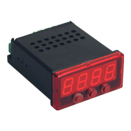
Manual for connection and operation of GIR 230 FR page 4 of 20 2. Introduction The GIR 230 FR is a microprocessor controlled displaying, monitoring and controlling device. The device is supporting one interface for the connection of: - Frequency (TTL or switching contact) The device features three switching outputs (2 * Relays, 1 * NPN-Output), which can be configured as 2- point-controller, 3-point-controller, 2-point-controller with min./max. -
Page 5: Connecting An Input Signal
E33.0.02.6C-02 Manual for connection and operation of GIR 230 FR page 5 of 20 3.3. Connecting an input signal Please take care not to exceed the limitations of the inputs when connecting the device as this may lead to destruction of the device.. -
Page 6: Connecting A Counter Signal
E33.0.02.6C-02 Manual for connection and operation of GIR 230 FR page 6 of 20 3.3.2. Connecting a counter signal When configuring the device you can select 3 different input signal modes similar to the connection of frequency- and rotation-signals. The connection of a sensor-signal for a counter-signal is the same used for the frequency- and rotation-signal. -
Page 7: Connecting Switching Outputs
E33.0.02.6C-02 Manual for connection and operation of GIR 230 FR page 7 of 20 3.4. Connecting switching outputs The switching outputs are depending on the device’s configuration of the selected output func- tions. (see chapter 4.2) Hint: In order to avoid unwanted or wrong switching processes, we suggest to connect the device’s switching outputs after you have configured the device’s switching outputs... -
Page 8: Configuration Of The Device
E33.0.02.6C-02 Manual for connection and operation of GIR 230 FR page 8 of 20 4. Configuration of the device Please note: When you are configuring the device and don’t press any button for more than 60 sec. the configuration of the device will be cancelled. The changes you made will not be saved and will be lost! Hint: The buttons 2 and 3 are featured with a ‘roll-function‘. -
Page 9: Measuring Frequency (Ttl, Switching Contact)
E33.0.02.6C-02 Manual for connection and operation of GIR 230 FR page 9 of 20 4.2. Measuring frequency (TTL, switching contact) This chapter describes how to configure the device for measuring frequency. This instruction demands that you selected “FrEq“ as your desired input type like it is explained in chapter 4.1. -
Page 10: Measuring Of Rotation Speed (Ttl, Switching-Contact)
E33.0.02.6C-02 Manual for connection and operation of GIR 230 FR page 10 of 20 4.3. Measuring of rotation speed (TTL, switching-contact) This chapter describes how to configure the device for measuring rotation speed. This instruction demands that you selected “rPn“ as your desired input type like it is explained in chapter 4.1. - Page 11 E33.0.02.6C-02 Manual for connection and operation of GIR 230 FR page 11 of 20 Press button 1 to validate your selection. The display shows “diu“ again. Press button 1 again. The display shows “Co.Hi“ (counter high = upper counting range limit).
-
Page 12: Selection Of The Output Function
E33.0.02.6C-02 Manual for connection and operation of GIR 230 FR page 12 of 20 4.5. Selection of the output function After configuration of the input (chapter 4.2 – 4.7) you have to select the output function. The display shows “outP“ (output). -
Page 13: Switchpoints And Alarm-Boundaries
E33.0.02.6C-02 Manual for connection and operation of GIR 230 FR page 13 of 20 5. Switchpoints and alarm-boundaries Please note: The settings of the switchpoints will be cancelled, when no button was pressed for more than 60 sec. changes you may have made already won‘t be saved and will be lost! Hint: The buttons 2 and 3 are featured with a ‘roll-function‘. -
Page 14: 2-Point-Controller With Alarm Function, 3-Point-Controller With Alarm Function
E33.0.02.6C-02 Manual for connection and operation of GIR 230 FR page 14 of 20 5.2. 2-point-controller with alarm function, 3-point-controller with alarm function This chapter describes how to configure the device as a 2-point-controller with alarm function or 3-point- controller with alarm function. This instruction demands that you selected “2P.AL“ or “3P.AL“ as your desired output function. -
Page 15: Minimum/Maximum-Alarm
E33.0.02.6C-02 Manual for connection and operation of GIR 230 FR page 15 of 20 5.3. Minimum/maximum-alarm This chapter describes how to configure the device‘s alarm boundaries for min-/max-alarm-monitoring. This instruction demands that you selected “AL“ as your desired output function. -
Page 16: Offset- And Slope-Adjustment
E33.0.02.6C-02 Manual for connection and operation of GIR 230 FR page 16 of 20 8. Offset- and slope-adjustment The offset and slope-adjustment function can be used for compensating the tolerance of the used probes. Please note: The settings of the offset- / slope-adjustment will be cancelled, when no button was pressed for more than 60 sec. -
Page 17: Error Codes
E33.0.02.6C-02 Manual for connection and operation of GIR 230 FR page 17 of 20 9. Error codes When detecting an operating state which is not permissible, the device will display an error code The following error codes are defined: Err.1: Exceeding of the measuring range Indicates that the valid measuring range of the device has been exceeded. -
Page 18: Specification
E33.0.02.6C-02 Manual for connection and operation of GIR 230 FR page 18 of 20 10. Specification Absolute maximum ratings: Performance data Limit values Connection Notes between Min. max. min. max. 207 V 244 V 253 V Supply voltage 3 and 4... - Page 19 E33.0.02.6C-02 Manual for connection and operation of GIR 230 FR page 19 of 20 Enclosure: main housing: fibre-glass-reinforced noryl front view-panel: polycarbonate Dimensions: 24 x 48 mm (front-panel cut out). Installation depth: approx. 65 mm (incl. screw-in/plug-in clamps) Panel mounting: via VA-spring-clip.
- Page 20 E33.0.02.6C-02 Manual for connection and operation of GIR 230 FR page 20 of 20...
Need help?
Do you have a question about the GIR 230 FR and is the answer not in the manual?
Questions and answers