Table of Contents
Advertisement
Quick Links
Manual for connection and operation of the GIR 2002 NS / DIF - ...
SA 839-02
page 1 of 24
Manual for connection and operation of
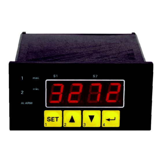
GIA 2002 NS / DIF - ...
as of version 2.7
GREISINGER
electronic GmbH
D - 93128 Regenstauf, Hans-Sachs-Straße 26
Phone: 0049 9402 / 9383-0, Fax: 0049 9402 / 9383-33, e-mail: info@greisinger.de
Advertisement
Table of Contents

Related Manuals for GREISINGER GIA 2002 NS/DIF Series


Summary of Contents for GREISINGER GIA 2002 NS/DIF Series
- Page 1 1 of 24 Manual for connection and operation of GIA 2002 NS / DIF - ... as of version 2.7 GREISINGER electronic GmbH D - 93128 Regenstauf, Hans-Sachs-Straße 26 Phone: 0049 9402 / 9383-0, Fax: 0049 9402 / 9383-33, e-mail: info@greisinger.de...
- Page 2 Manual for connection and operation of the GIR 2002 NS / DIF - ... SA 839-02 page 2 of 24 I N D E X 1. SAFETY REGULATIONS ............................3 2. INTRODUCTION ................................ 4 3. ELECTRIC CONNECTION ............................5 3.1. Terminal assignment ..............................5 3.2.
-
Page 3: Safety Regulations
Manual for connection and operation of the GIR 2002 NS / DIF - ... SA 839-02 page 3 of 24 1. Safety regulations This device was designed and tested considering the safety regulations for electronic measuring devices. Faultless operation and reliability in operation of the measuring device can only be assured if the General Safety Measures and the devices specific safety regulations mentioned in this users manual are considered. - Page 4 Manual for connection and operation of the GIR 2002 NS / DIF - ... SA 839-02 page 4 of 24 2. Introduction The GIR 2002 is a microprocessor controlled displaying, moni- toring and controlling device. The device supports one connection facility for: - Standard transmitter signals (only 1 signal type possible) Alarm 2x 0-20mA, 2x 4-20mA or 2x 0-10V)
-
Page 5: Electric Connection
Manual for connection and operation of the GIR 2002 NS / DIF - ... SA 839-02 page 5 of 24 3. Electric Connection Wiring and commissioning of the device must be carried out by skilled personnel only. In case of wrong wiring the device may be destroyed. We can not assume any warranty in case of wrong wiring of the device. - Page 6 Manual for connection and operation of the GIR 2002 NS / DIF - ... SA 839-02 page 6 of 24 3.2.2. At options REL3 or NPN3 button 5 EASYBus-Interface EASYBus-Interface Input1: (Input signal according to type plate) Input2: (Input signal according to type plate) Not used Input: GND Transmitter supply voltage -...
-
Page 7: Connection Data
Manual for connection and operation of the GIR 2002 NS / DIF - ... SA 839-02 page 7 of 24 3.3. Connection data typical limitations between notes terminals min. max. min. max. or corresponding des- 207 V 244 V 253 V Supply voltage 1 and 2 ignation on the type... - Page 8 Manual for connection and operation of the GIR 2002 NS / DIF - ... SA 839-02 page 8 of 24 3.4. Connecting an input signal Please take care not to exceed the limitations of the inputs when connecting the device as this may lead to destruction of the device.
-
Page 9: Selecting An Input Signal Type
Manual for connection and operation of the GIR 2002 NS / DIF - ... SA 839-02 page 9 of 24 4. Configuration of the measuring input General description and notes to the operating of the menu By means of button 1 you can go to the next parameter. Additionally a given changing in the parameter setting can be confirmed by this button and the new value will be saved. - Page 10 Manual for connection and operation of the GIR 2002 NS / DIF - ... SA 839-02 page 10 of 24 4.2. Measuring voltage and current (0-10V, 0-20mA, 0-20mA) This chapter describes how you configure the device for measuring voltage- or current-signals from an ex- ternal transmitter.
- Page 11 Manual for connection and operation of the GIR 2002 NS / DIF - ... SA 839-02 page 11 of 24 When pressing button 1 again, the display will show “FiLt“ (Filter = digital filter). Use button 2 or button 3 to select the desired filter [in sec.]. Selectable values: off, 0.01 ...
-
Page 12: Scaling The Analog Output
Manual for connection and operation of the GIR 2002 NS / DIF - ... SA 839-02 page 12 of 24 5.1. Scaling the analog output The analog output can be scaled arbitrary within the display range. Turn on the device and wait after it finished its built-in segment Alarm test. -
Page 13: Selection Of The Output Function
Manual for connection and operation of the GIR 2002 NS / DIF - ... SA 839-02 page 13 of 24 6. Configuration of the output functions (only for GIR 2002) A change of the input configuration can possibly influence the switching points and alarm bounda- ries. -
Page 14: 2-Point-Controller, 3-Point-Controller
Manual for connection and operation of the GIR 2002 NS / DIF - ... SA 839-02 page 14 of 24 = Alarm inverse means, that the output will be active when there is no alarm! Press button 1 to validate the selected output function. The display shows “outP“ again. Hint: The settings for the switching and alarm points can be made later in an extra menu (see chapter 7) 6.2. -
Page 15: 2-Point-Controller With Alarm Function, 3-Point-Controller With Alarm Function
Manual for connection and operation of the GIR 2002 NS / DIF - ... SA 839-02 page 15 of 24 6.3. 2-point-controller with alarm function, 3-point-controller with alarm function This chapter describes how to configure the device as a 2-point-controller with alarm function or 3-point- controller with alarm function how to adjust the switching values and alarm boundaries. - Page 16 Manual for connection and operation of the GIR 2002 NS / DIF - ... SA 839-02 page 16 of 24 6.4. Min-/Max-Alarm (individual or common) This chapter describes how to adjust the device„s alarm boundaries for min-/max-alarm-monitoring. This instruction demands that you selected “AL.F1“ or “AL.F2“ as your desired output function like it is ex- plained in chapter 6.1.
-
Page 17: Menu Calling
Manual for connection and operation of the GIR 2002 NS / DIF - ... SA 839-02 page 17 of 24 7.1. Menu calling When pressing button 1 for >2 seconds the menu to select the switching points and alarm-boundaries will be called. - Page 18 Manual for connection and operation of the GIR 2002 NS / DIF - ... SA 839-02 page 18 of 24 Press button 1 to validate your selection. The display shows “2.off“again. When pressing button 1 again, the display shows “1.on“ again. Now you have finished the adjustment of the switching points of the device.
-
Page 19: Min-/Max-Value Memory
Manual for connection and operation of the GIR 2002 NS / DIF - ... SA 839-02 page 19 of 24 => The alarm will be starting after the temperature rises above –15°C and stays above –15°C for the entered delay time or after it had been falling below –30°C and stays below –30°C for the en- tered delay time. -
Page 20: Serial Interface
Manual for connection and operation of the GIR 2002 NS / DIF - ... SA 839-02 page 20 of 24 9. Serial interface The device features one EASYBus-Interface. You can use the device as a full function EASYBus-device. The serial interface allows the device to communicate with a host computer. Data polling and data transfer is done in master/slave mode, so the device will only send data on demand. -
Page 21: Error Codes
Manual for connection and operation of the GIR 2002 NS / DIF - ... SA 839-02 page 21 of 24 11. Error codes When detecting an operating state which is not permissible, the device will display an error code. The following error codes are defined: Err.1: Exceeding of the measuring range Indicates that the valid measuring range of the device has been exceeded. - Page 22 Manual for connection and operation of the GIR 2002 NS / DIF - ... SA 839-02 page 22 of 24 Er.11: Value could not be calculated Indicates a measuring value, needed for calculation of the display value, is faulty or out of range. Possible causes: - Incorrect scale.
-
Page 23: Specification
Manual for connection and operation of the GIR 2002 NS / DIF - ... SA 839-02 page 23 of 24 12. Specification Absolute maximum ratings: see chapter 3.3. (Connection data) Measuring inputs: Standard inputs for Input type Signal l Range Resolution Note Standard-... -
Page 24: Disposal Notes
Manual for connection and operation of the GIR 2002 NS / DIF - ... SA 839-02 page 24 of 24 , 50/60 Hz (standard) or the corresponding designation on the label on the housing Power supply: 230 V Power consumption: approx. 5 VA (GIA2000) or approx. 6 VA (GIR2002) Nominal temp.: 25 °C Operating ambient: -20 to +50 °C...
Need help?
Do you have a question about the GIA 2002 NS/DIF Series and is the answer not in the manual?
Questions and answers