Table of Contents
Advertisement
Quick Links
GIR1002 FR / GIA1000 FR
Connecting and Operating Manual
This connecting and operating manual may be subject to technical alternations.
Connecting and Operating Manual
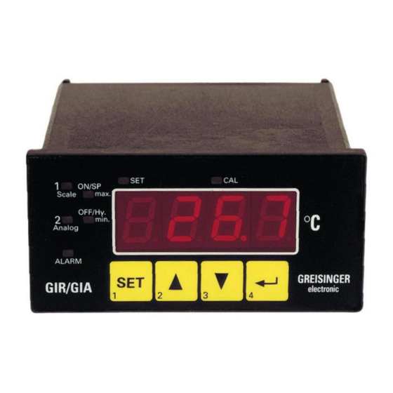
GIR1002 FR
GIA1000 FR
Version: 4.03
SET
1
ON/SP
Scale
max.
OFF/Hy.
2
min.
Analog
ALARM
SET
G IR/G IA
1
In accordance with
EN50081-1 and EN50082-2
for unrestricted use in
housing and industrial areas
CAL
2
3
4
Version: 4.03-3
page: 1
Advertisement
Table of Contents

Summary of Contents for GREISINGER GIR1002 FR
- Page 1 GIR1002 FR / GIA1000 FR Connecting and Operating Manual Version: 4.03-3 page: 1 Connecting and Operating Manual GIR1002 FR GIA1000 FR Version: 4.03 ON/SP Scale max. OFF/Hy. min. Analog ALARM G IR/G IA In accordance with EN50081-1 and EN50082-2 for unrestricted use in housing and industrial areas This connecting and operating manual may be subject to technical alternations.
- Page 2 GIR1002 FR / GIA1000 FR Connecting and Operating Manual Version: 4.03-3 page: 2 Index Introduction ...................... page: 3 Safety Regulations................... page: 3 Electric Connection ..................page: 4 Terminal Assignment ........................page: 4 Assignment Diagram ........................page: 4 Transmitter Connection...................page: 5 Technical Specifications..................
-
Page 3: Safety Regulations
The front side of the controller is splash water proof and wipe resistant fulfilling all requirements of the IP65 rating. All programmable parameters of the GIR1002 FR are stored in an EEPROM and in case of a current failure they will be safe for at least ten years. -
Page 4: Electric Connection
4 Electric Connection All connections for the GIR1002 FR are located at the back side of the device. Connections are made via screw-type/plug-in terminals. Make it a rule to mount screw-type/plug-in terminals while they are still loose and to put them on only afterwards. -
Page 5: Transmitter Connection
GIR1002 FR / GIA1000 FR Connecting and Operating Manual Version: 4.03-3 page: 5 Transmitter Connection Connection of a frequency transmitter in 3-wire technologie * = only necessary for rransmitter with GIR1002 NPN open collector output. Signal Suffested value (e.g. 10k) please refer to user manual of the transmitter Freq. -
Page 6: Operation
6 Operation Start-up As soon as the supply voltage has been applied the GIR1002 FR will carry out a ssystem test for approx. 8s. Then the current measuring value will be displayed. Table of Functions The various functions are called up/input by means of the 4 buttons located at the front side of the device. - Page 7 GIR1002 FR / GIA1000 FR Connecting and Operating Manual Version: 4.03-3 page: 7 Alarm reset and deactivate tara function To be called up by: pressing button 4 for approx. 4s please refer to “ display of current measuring value” Display: Display of max.
- Page 8 GIR1002 FR / GIA1000 FR Connecting and Operating Manual Version: 4.03-3 page: 8 Display/setting of breaking point/hysteresis for switching output 1 or 2 pressing button 1 till LEDs “ SET” , "1" or “ 2” and “ OFF/Hy” are illuminated.
- Page 9 11. Press button 1 (front side). Press miniature push button on the back side of the GIR1002 FR (located behind the sensor connection terminal) in addition (for approx. 1 s) till LED “ CAL“ (on front side) is flashing.
- Page 10 4. 8) LEDs “ Analog“ , “ min.“ and LED “ CAL“ are illuminated. The display will show the measuring value stored in the GIR1002 FR for which a 4mA signal will be given at the analog output.
-
Page 11: Fault Codes
GIR1002 FR / GIA1000 FR Connecting and Operating Manual Version: 4.03-3 page: 11 Additional Configuration Notes For Flow Transducers: If a GIR1002FR is used with one of the flow transducers mentioned below, we suggest the following settings: configuration point 2: choose input mode "In.11". - Page 12 The serial interface of the GIR1002 FR allows communication of the device with a host computer. Data polling and transfer is done in the master/slave mode, i.e. the GIR1002 FR will only transmit data upon request. A separate device address can be attributed to each GIR1002 FR. Addresses 0 to 15 are implemented.
- Page 13 Indicates the beginning of a data transfer process. ‘ #’ is issued by the GIR1002 FR prior to starting transfer of data to the host. If the character ‘ #’ is transferred by the host after issuing of the device number, the GIR1002 FR device will know that data are to be transferred from the host to the GIR1002 FR (programming of GIR1002 FR).
- Page 14 The value is represented in hexadecimal printable ASCII characters. The GIR1002 FR treats all values as 16 bit words, which means that a range of values from -32768 to +32767 and correspondingly a range from 8000H to 7FFFH can be displayed.
- Page 15 Data format 2: This format is used to call up and reset the system state. Data bytes D1 to D4 contain information regarding the alarm and fault state of the GIR1002 FR. The assignment is as follows: Data byte D2:...


Need help?
Do you have a question about the GIR1002 FR and is the answer not in the manual?
Questions and answers