Table of Contents
Advertisement
Quick Links
Smart encoders & actuators
Ax58 CB
Ax58S CB
AxC58 CB
CC-CB / CC-CB-C
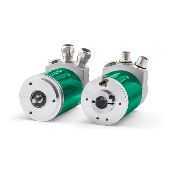
• AS58 singleturn encoder with resolution up to 13 bits
• AM58 multiturn encoder with resolution up to 25 bits
• Connection cap with M12 connectors or PG cable outlets
• CANopen in compliance with DS 301 and DS 406 profiles
Suitable for the following models:
AS58, AS58S CB + CC-CB/CC-CB-C
•
ASC58, ASC59, ASC60 CB + CC-CB/CC-CB-C
•
AM58, AM58S CB + CC-CB/CC-CB-C
•
AMC58, AMC59, AMC60 CB + CC-CB/CC-
•
CB-C
Lika Electronic
User's guide
•
Tel. +39 0445 806600
DS406 encoder profile
General Contents
Preliminary information
1 - Safety summary
2 - Identification
3 - Mounting instructions
4 - Electrical connections
5 - Quick reference
6 - CANopen® interface
7 – Setting-up
8 – Default parameters list
•
info@lika.biz
20
22
23
28
37
41
81
85
•
www.lika.biz
9
Advertisement
Table of Contents


Need help?
Do you have a question about the CANopen A 58 CB Series and is the answer not in the manual?
Questions and answers