Table of Contents
Advertisement
Quick Links
Smart encoders & actuators
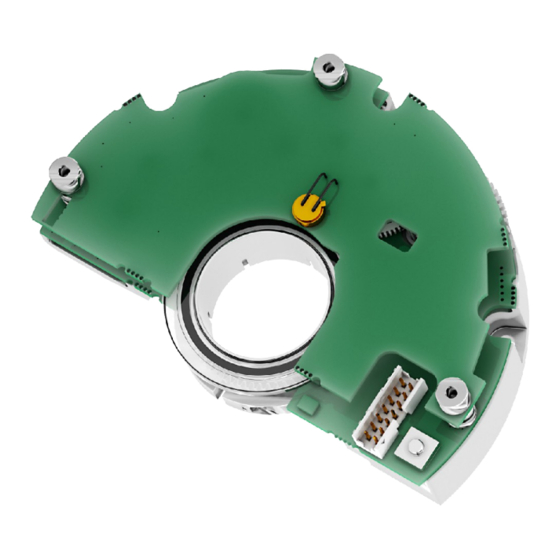
AMM8A
• Multiturn modular encoder with optical scanning
• Compact and low-profile design for comfortable installation
• Resolution up to 21 x 12 bits (2,097,152 cpr x 4,096 rev.)
• SSI / BiSS C-mode interface with Sine/Cosine additional track
• For direct integration into robots, motors and OEM applications
Suitable for the following models:
AMM8Axx/xxxxxBGx...
•
AMM8Axx/xxxxxGGx...
•
AMM8Axx/xxxxxSCx...
•
Lika Electronic
User's guide
•
Tel. +39 0445 806600
Table of Contents
1 - Safety summary
2 - Identification
3 - Get started
4 - Mounting instructions
5 - Electrical connections
6 - Calibration and synchronization procedure 38
7 - SSI interface
8 - BiSS C-mode interface
9 - Default parameters list
•
info@lika.biz
11
14
15
16
31
54
57
77
•
www.lika.biz
Advertisement
Table of Contents

Related Manuals for Lika AMM8A


Summary of Contents for Lika AMM8A
-
Page 1: User's Guide
User's guide Smart encoders & actuators AMM8A • Multiturn modular encoder with optical scanning • Compact and low-profile design for comfortable installation • Resolution up to 21 x 12 bits (2,097,152 cpr x 4,096 rev.) • SSI / BiSS C-mode interface with Sine/Cosine additional track •... - Page 2 Tous droits réservés. This document and information contained herein are the property of Lika Electronic s.r.l. and shall not be reproduced in whole or in part without prior written approval of Lika Electronic s.r.l. Translation, reproduction and total or partial modification (photostat copies, film and microfilm included and any other means) are forbidden without written authorisation of Lika Electronic s.r.l.
-
Page 3: Table Of Contents
2 - Identification..................................14 3 - Get started....................................15 4 - Mounting instructions..............................16 4.1 AMM8A encumbrance sizes............................16 4.2 Mechanical characteristics of the mounting support..................17 4.3 Mounting the encoder and executing the fast synchronization procedure.........18 4.4 Mounting the encoder and executing the complete synchronization procedure......25 5 - Electrical connections...............................31... - Page 4 6.6 Information, warning and error messages......................51 Amplitude signals error. Run a new calibration?.................51 Calibration mode is not active.........................51 Calibration OK..............................52 Current calibration is not adequate (code …). Run a new calibration?......52 Device connected..............................52 Device not connected.............................52 Fix the encoder..............................52 IF90 not connected............................53 Synchronization OK............................53...
- Page 5 N° of bits used for singleturn resolution....................69 N° of bits used for multiturn resolution....................69 Resolution of sine-cosine signals.........................69 Work cycles counter..............................69 Work cycles warning limit..........................70 Acceleration................................70 Acceleration peak warning limit........................71 Speed....................................71 Speed peak warning limit..........................72 Encoder warnings and errors...........................72 Work cycles limit reached...........................72 Acceleration peak limit reached......................73...
-
Page 6: Subject Index
Subject Index IF90 not connected............53 Information per revolution..........66 Acceleration..............58, 70 Interface................41 Acceleration peak limit reached........73 Acceleration peak warning limit.......71 Amplitude signals error..........51 Load and save default parameters......63 BACKLASH CHECKED............50 Manufacturer ID...............76 Mechanical alignment...........45 Multiturn gear error............73 Calibration mode is not active........51 Calibration OK..............52 Calibration verification..........48 N°... - Page 7 Synchronization OK............53 Work cycles counter............69 Synchronization single/multi turn......47 Work cycles limit reached..........72 Work cycles save error...........73 Work cycles warning limit..........70 Track offset calibration..........46 Zero setting OK..............53 Warning................59...
-
Page 8: Typographic And Iconographic Conventions
In this guide, to make it easier to understand and read the text the following typographic and iconographic conventions are used: parameters and objects both of Lika device and interface are coloured in GREEN; • alarms are coloured in RED;... -
Page 9: Preliminary Information
To achieve proper installation and correct operation of the encoder a software is expressly developed and released by Lika Electronic. It allows the operator to set up and calibrate the AMM8A modular encoder during installation. The program is supplied for free and can be installed in any PC fitted with a Windows operating system (Windows XP or later). - Page 10 Further accessories to be ordered separately: A) EXC-D15M-S71-A16-1,0-FCI-S71 cable for calibration and synchronization (see on page 38) 15-pin male D-Sub connector to the IF90-SC interface • D-Sub connector 14-pin SQW-107-01-F-D-VS connector • modular encoder unit B) EC-FCI-LK-TF12-0,5 connection cable for operation (see on page 32) 0.5 m cordset with SQW-107-01-F-D-VS...
-
Page 11: Safety Summary
• failure to comply with these precautions or with specific warnings elsewhere in this manual violates safety standards of design, manufacture, and intended use of the equipment; • Lika Electronic assumes no liability for the customer's failure to comply with these requirements. 1.2 Electrical safety •... -
Page 12: Mechanical Safety
AMM8A SSI & BiSS C-mode can be situated both on the device side and on user’s side. The best solution to minimize the interference must be carried out by the user. 1.3 Mechanical safety • Install the device following strictly the information in the “4 - Mounting instructions”... - Page 13 AMM8A SSI & BiSS C-mode avoid flexing the disk, exposing it to direct sunlight, excessive heat • and/or humidity; if dust or fingerprints get on to the disk, wipe with a soft dry cloth or • camera lens tissue; wipe the disk using circular motions; more stubborn fingerprints or stains can be removed using a soft cloth lightly moistened with a few drops of alcohol;...
-
Page 14: Identification
Information is listed in the delivery document too. Please always quote the order code and the serial number when reaching Lika Electronic. For any information on the technical characteristics of the product refer to the technical catalogue. -
Page 15: Get Started
AMM8A SSI & BiSS C-mode 3 - Get started For standard installation and set up procedure, follow the instructions in the “4.3 Mounting the encoder and executing the fast synchronization procedure” section on page 18. As an alternative or in case the fast synchronization procedure does not succeed, you can follow the instructions in the “4.4 Mounting the encoder and... -
Page 16: Mounting Instructions
AMM8A SSI & BiSS C-mode 4 - Mounting instructions WARNING Installation must be carried out by qualified personnel only, with power supply disconnected and mechanical parts compulsorily in stop. WARNING Before handling and mounting the device please be sure to read carefully the handling instructions and safety information reported in the “1.4 Specific... -
Page 17: Mechanical Characteristics Of The Mounting Support
AMM8A SSI & BiSS C-mode 4.2 Mechanical characteristics of the mounting support This encoder module is specifically designed for installation in motors having the mechanical characteristics indicated in the following drawing. (values are expressed in mm) MAN AMM8A SSI_BiSS E 1.10.odt... -
Page 18: Mounting The Encoder And Executing The Fast Synchronization Procedure
For your ease and convenience, before starting the installation, please make sure that the mounting kit and tools are ready to hand. Always refer to the mounting tolerances specified in the “4.1 AMM8A encumbrance sizes” section on page 16. WARNING Before installation, carefully clean the code disk from dust or •... - Page 19 AMM8A SSI & BiSS C-mode Step 1 Place the PF5013 spacing tool 1 against the shaft 2. Insert the code disk 3 into the shaft 2 and lay it down on the spacing tool 1; always handle the code disk 3 by grasping its collar.
- Page 20 AMM8A SSI & BiSS C-mode Step 3 Slide the encoder unit 5 over the code disk 3 and move it forward until it is against the shaft 2 thoroughly; then move it back slightly; make sure that the metal enclosure of the encoder unit 5 does not hit or touch the code disk 3;...
- Page 21 AMM8A SSI & BiSS C-mode Step 5 Tighten the three bolts 7 to fasten the encoder unit 5 in position, torque to 1.3 Nm max. Hold the encoder unit 5 down and avoid any movements while tightening. Step 6 Connect the EC-FCI-LK-TF12-0,5 cable 8 to the 14-pin male connector 9 of the encoder unit 5 on one side, to the subsequent electronics on the other side.
- Page 22 AMM8A SSI & BiSS C-mode Step 7 After installing the encoder unit 5, it is necessary to carry out the procedure meant to synchronize the gears and the single-multi turn information code. The proper synchronization is achieved by uploading at power-on the offset value calculated during the synchronization procedure.
- Page 23 AMM8A SSI & BiSS C-mode Step 10 If the ERROR LED 13 is on solidly and either the BiSS Error bit or the Nonius error bit or both are active (low and high respectively), the encoder unit 5 is not able to read the code disk 3 (maybe you turned on the power before mounting the encoder unit 5 on the disk?).
- Page 24 6 Encoder warnings and errors the register 74 is set to =”1”. The system cannot operate properly, the error message cannot be reset. Please contact Lika Electronic After Sales Service. MAN AMM8A SSI_BiSS E 1.10.odt 4 - Mounting instructions...
-
Page 25: Mounting The Encoder And Executing The Complete Synchronization Procedure
For your ease and convenience, before starting the installation, please make sure that the mounting kit and tools are ready to hand. Always refer to the mounting tolerances specified in the “4.1 AMM8A encumbrance sizes” section on page 16. WARNING Before installation, carefully clean the code disk from dust or •... - Page 26 AMM8A SSI & BiSS C-mode Step 1 Place the PF5013 spacing tool 1 against the shaft 2. Insert the code disk 3 into the shaft 2 and lay it down on the spacing tool 1; always handle the code disk 3 by grasping its collar.
- Page 27 AMM8A SSI & BiSS C-mode Step 3 Slide the encoder unit 5 over the code disk 3 until the screw holes 6 match up; make sure that the metal enclosure of the encoder unit 5 does not hit or touch the code disk 3;...
- Page 28 AMM8A SSI & BiSS C-mode Step 5 EXC-D15M-S71-A16-1,0-FCI-S71 cable 10 to the 14-pin male Connect the connector 9 of the encoder unit 5 on one side, to the connector of the interface on the other side. Step 6 Now you need to align the encoder unit 5 over the code disk 3. For complete information on the mechanical alignment, the calibration procedure and the synchronization operation using the IF90-SC program, please refer to the “6 -...
- Page 29 AMM8A SSI & BiSS C-mode Step 7 Adjust the position of the encoder unit 5 until it is well aligned over the code disk 3 and the Fix the encoder message appears on the calibration interface page (see the Figure in the previous Step 6).
- Page 30 AMM8A SSI & BiSS C-mode Step 9 Finalize the calibration and synchronization procedure. After installation, calibration and synchronization procedures are carried out, EXC-D15M-S71-A16-1,0-FCI-S71 replace the calibration cable with the EC-FCI-LK-TF12-0,5 connection cable. MAN AMM8A SSI_BiSS E 1.10.odt 4 - Mounting instructions...
-
Page 31: Electrical Connections
AMM8A SSI & BiSS C-mode 5 - Electrical connections WARNING Power supply must be turned off before performing any electrical connection! If wires of unused signals come in contact, irreparable damage may be caused to the device. Thus they must be cut at different lengths and insulated singularly. -
Page 32: 98414-G06-14Lf 14-Pin Male Connector
AMM8A SSI & BiSS C-mode 5.1 98414-G06-14LF 14-pin male connector Mating connector: SQW-107-01-F-D-VS 5.2 TF12 cable specifications Model : LIKA TF12 encoder cable Cross section : 6 x 2 twisted pairs (28 AWG) Jacket : special flame retardant PVC compound Shield : tinned copper braid, coverage >... -
Page 33: Zero Setting / Preset Input
AMM8A SSI & BiSS C-mode input is connected to +Vdc, the position value increases when the encoder disk rotates counter-clockwise. CW and CCW rotations are viewed from flange side. If not used, connect the Counting direction input to 0Vdc (standard counting direction, see the Figure). -
Page 34: 5Vdc Out
AMM8A SSI & BiSS C-mode direction. We suggest setting the zero setting/preset function when the encoder shaft is not running. If not used, connect the Zero setting/Preset input to 0Vdc. WARNING In the BiSS C-mode interface, the Zero setting/Preset input is active only when... -
Page 35: Output Signals Voltage Level
AMM8A SSI & BiSS C-mode results from differential signals detection. The frequency of output signals is proportional to the rotational speed of the encoder (max. 80 kHz). 5.7.1 Output signals voltage level The voltage level refers to the differential value between normal and inverted signal (differential). -
Page 36: Error Led
(low and high respectively), the encoder unit 5 is not able to read the code disk 3 (maybe you turned on the power before mounting the encoder unit 5 on the disk?). The error cannot be reset. Please contact Lika Electronic After Sales Service. -
Page 37: Calibration Led
AMM8A SSI & BiSS C-mode 5.8.2 CALIBRATION LED After installing properly the encoder unit 5 and the code disk 3, the operator can start the calibration procedure (see on page 18). When he turns on the power supply while keeping pressed the button 12, after about 2 sec. -
Page 38: Calibration And Synchronization Procedure
To close the program press the EXIT button in the title bar. WARNING Use the release version of the IF90-SC program from v1.1 on. 6.2 IF90-SC interface MAN AMM8A SSI_BiSS E 1.10.odt 6 - Calibration and synchronization procedure 38 of 80... -
Page 39: Before Launching The Calibration And Synchronization Procedure
25; disconnect the EC-FCI-LK-TF12-0,5 cable from the 98414-G06-14LF 14- • male connector of the modular encoder and connect the EXC- D15M-S71-A16-1,0-FCI-S71 cable D; MAN AMM8A SSI_BiSS E 1.10.odt 6 - Calibration and synchronization procedure 39 of 80... -
Page 40: Installing The If90-Sc Interface Usb Drivers
After installation you can launch the executable file and open the encoder calibration interface; to know more refer to the next section. MAN AMM8A SSI_BiSS E 1.10.odt 6 - Calibration and synchronization procedure 40 of 80... -
Page 41: Encoder Calibration And Synchronization Interface
When you choose the encoder model you automatically select also the voltage to be supplied to the encoder: if you select a wrong model and perhaps MAN AMM8A SSI_BiSS E 1.10.odt 6 - Calibration and synchronization procedure 41 of 80... - Page 42 For any information please refer to the “6.3 Before launching the calibration and synchronization procedure” section on page 39. MAN AMM8A SSI_BiSS E 1.10.odt 6 - Calibration and synchronization procedure 42 of 80...
-
Page 43: Establishing A Connection To The Encoder
STOP PROCEDURE. The duration of the process, expressed in minutes and seconds, will be indicated on the right (Elapsed time). MAN AMM8A SSI_BiSS E 1.10.odt 6 - Calibration and synchronization procedure 43 of 80... - Page 44 On the contrary, if an error occurs during the check operation, a red will appear next to the Parameters control item. The encoder must be sent back to Lika Electronic for some checks. MAN AMM8A SSI_BiSS E 1.10.odt 6 - Calibration and synchronization procedure 44 of 80...
-
Page 45: Aligning The Encoder
On the contrary, if an error occurs during the mechanical alignment operation, a will appear next to the Mechanical alignment item. You will need to repeat the operation and check, for instance, if the disk is dirty. MAN AMM8A SSI_BiSS E 1.10.odt 6 - Calibration and synchronization procedure 45 of 80... -
Page 46: Calibrating The Track Offset
Track offset calibration item. It ten attempts, a red may be necessary to clean the disk and perform a new mechanical alignment operation. MAN AMM8A SSI_BiSS E 1.10.odt 6 - Calibration and synchronization procedure 46 of 80... -
Page 47: Synchronizing Singleturn And Multiturn Positions
On the contrary, if an error occurs during the synchronization procedure, a red will appear next to the Synchronization single/multi turn item. It may be necessary to clean the disk and perform a new calibration procedure. MAN AMM8A SSI_BiSS E 1.10.odt 6 - Calibration and synchronization procedure 47 of 80... -
Page 48: Verification Of Calibration
On the contrary, if an error occurs during the verification of calibration will appear next to the Calibration verification item. It procedure, a red may be necessary to clean the disk and perform a new calibration procedure. MAN AMM8A SSI_BiSS E 1.10.odt 6 - Calibration and synchronization procedure 48 of 80... -
Page 49: Checking The Gear Backlash
He must rely on his own sensitivity and experience: movement must be steady and smooth, without any irregularities and jams. MAN AMM8A SSI_BiSS E 1.10.odt 6 - Calibration and synchronization procedure 49 of 80... -
Page 50: Reading The Position Of The Encoder
On the contrary, when the logic state of the bits is high (=”1”), no error or warning is active in the system and the relevant field is coloured white. MAN AMM8A SSI_BiSS E 1.10.odt 6 - Calibration and synchronization procedure 50 of 80... -
Page 51: Information, Warning And Error Messages
For any information please refer to the “6.3 Before launching the calibration and synchronization procedure” section on page 39. MAN AMM8A SSI_BiSS E 1.10.odt 6 - Calibration and synchronization procedure 51 of 80... -
Page 52: Calibration Ok
Finally he must press the DONE button to complete the mechanical alignment operation. For any information please refer to the “6.5.5 Aligning the encoder” section on page 45. MAN AMM8A SSI_BiSS E 1.10.odt 6 - Calibration and synchronization procedure 52 of 80... -
Page 53: If90 Not Connected
As soon as the zero setting operation is carried out positively, a green tick ( appears next to the MAKE ZERO SETTING item and the Zero setting OK message is displayed. MAN AMM8A SSI_BiSS E 1.10.odt 6 - Calibration and synchronization procedure 53 of 80... -
Page 54: Ssi Interface
AMM8A SSI & BiSS C-mode 7 - SSI interface Order codes: AMM8Axx/xxxxxBGx-... AMM8Axx/xxxxxGGx-... 7.1 SSI (Synchronous Serial Interface) Synchronous Serial SSI (the acronym for Interface) is a synchronous point-to-point serial interface engineered unidirectional data transmission between one Master and one Slave. -
Page 55: Msb Left Aligned" Protocol
AMM8A SSI & BiSS C-mode At each change of the clock signal and at each subsequent rising edge (2) one bit is clocked out at a time, up to LSB, so completing the data word transmission. The cycle ends at the last rising edge of the clock signal (3). This means that up to n + 1 rising edges of the clock signals are required for each data word transmission (where n is the bit resolution);... -
Page 56: Recommended Transmission Rates
AMM8A SSI & BiSS C-mode 7.3 Recommended transmission rates The SSI interface has a frequency of data transmission ranging between 100 kHz and 2 MHz. The CLOCK signal and the DATA signal comply with the “EIA standard RS-422”. The SSI clock frequency (baud rate) depends on the length of the cable and... -
Page 57: Biss C-Mode Interface
8 - BiSS C-mode interface Order code: AMM8Axx/xxxxxSC1-... AMM8Axx/xxxxxSC2-... Lika encoders are always Slave devices and comply with the “BiSS C-mode interface” and the “Standard encoder profile”. Refer to the official BiSS website for all information not listed in this manual (www.biss-interface.com). -
Page 58: Single Cycle Data Scd
AMM8A SSI & BiSS C-mode 8.2 Single Cycle Data SCD 8.2.1 SCD structure SCD data has a variable length according to the resolution of the encoder. It is nbitres+7 long where “nbitres” is the resolution of the encoder expressed in bits. -
Page 59: Warning
AMM8A SSI & BiSS C-mode Warning (1 bit) It is intended to communicate the normal or fault status of the Slave. When nW = “0”, a warning is active in the system. For a comprehensive list of the available warning messages and their meaning please refer to the registers... -
Page 60: Data
AMM8A SSI & BiSS C-mode DATA When you need to write in a register (RW = “01”), it allows to enter the value to be written in the register (transmitted from the Master to the Slave). When you need to read in a register (RW = “10”), it shows the value read in the register (transmitted from the Slave to the Master). -
Page 61: Profile Id
AMM8A SSI & BiSS C-mode N° of bits used for singleturn resolution N° of bits used for multiturn resolution Resolution of sine-cosine signals 59 … 5C Work cycles counter 5D … 5F Work cycles warning limit 60 … 62 Acceleration 63 …... -
Page 62: Serial Number
AMM8A SSI & BiSS C-mode Serial number [44 … 47, ro] These registers contain the serial number of the device expressed in hexadecimal notation. Register 44: year of production. Register 45: week of production. Registers 46 and 47: serial number in ascending order. -
Page 63: Load And Save Default Parameters
AMM8A SSI & BiSS C-mode Load and save default parameters Default parameters are set at the factory by Lika Electronic engineers to allow the operator to run the device for standard operation in a safe mode. As soon as the command is sent, the default parameters are uploaded and activated. All parameters which have been set previously are overwritten, thus previously set values are lost. -
Page 64: Data Type
AMM8A SSI & BiSS C-mode Data type It sets the type of data that is provided to output through SCD data frame (see on page 58). It can be either the encoder current position information (00) or the current speed information (10) or the current acceleration information (01). -
Page 65: Output Code
AMM8A SSI & BiSS C-mode Output code The encoder provides the absolute position or speed or acceleration information in the set code format: GRAY code (bit 5 = “0”) or BINARY code (bit 5 = “1”). Default = 1 (Binary) -
Page 66: Information Per Revolution
AMM8A SSI & BiSS C-mode CONFIGURATION SETTING EXAMPLE Configuration You need to set the following parameters next to the register: Data type = 00 = current encoder position information Enable preset = 0 = enable Output code = 1 = Binary... -
Page 67: Number Of Revolutions
AMM8A SSI & BiSS C-mode Number of revolutions [4E - 4F, ro] These registers are meant to show the number of physical revolutions. For information see the order code, the number of revolution can be up to 4,096 (AMM8Axx/xxxxx...). You can read the number of bits used for the number of revolutions also at the N°... - Page 68 AMM8A SSI & BiSS C-mode NOTE We suggest setting the preset when the encoder shaft is in stop. Preset registers structure: Register … … 2 … 2 … 2 … 2 … 2 PRESET SETTING EXAMPLE Preset You want to set the following...
-
Page 69: Device Type
AMM8A SSI & BiSS C-mode WARNING After having set the new counting direction it is necessary to set also a new preset. Device type [55, ro] This register describes the type of device. Default = 04h: multiturn rotary encoder with BiSS C-mode interface + sine- cosine additional signals (AMM8Axx/xxxxxSCx-...) -
Page 70: Work Cycles Warning Limit
AMM8A SSI & BiSS C-mode revolution occurs nearby the point where the counter changes its value. After increasing the counter value, if you move backward less than 1 revolution and then you move forward less than 2 revolutions, the counter does not increase its value;... -
Page 71: Acceleration Peak Warning Limit
AMM8A SSI & BiSS C-mode Acceleration peak warning limit value; if the registers are set to any value Acceleration greater than “00 00 00h”, the registers show the acceleration / deceleration peak reached by the encoder. The acceleration / deceleration peak Command can be reset by setting “08”... -
Page 72: Speed Peak Warning Limit
AMM8A SSI & BiSS C-mode show the speed peak reached by the encoder. The speed peak can be reset by Command setting “08” in the register. The speed value is expressed in RPM. The speed is sampled every 7.8125 msec.; the system detects speed values up to 7,324 RPM and records them with increments of 1 RPM. -
Page 73: Acceleration Peak Limit Reached
“08” in the register. Maybe there is a breakdown in the photoelements or in the mechanical gears. The system cannot operate properly. If the problem lingers, please contact Lika Electronic After Sales Service. Bit 4 Work cycles save error... -
Page 74: Synchronization Error
(=”1”). The system cannot operate properly, this error message cannot be reset. Please contact Lika Electronic After Sales Service. For complete information on the synchronization procedure please refer to the “4.3 Mounting the encoder and executing the fast synchronization procedure”... -
Page 75: Excessive Temperature Warning
ASCII code. Register ASCII Registers 78-7C = encoder model (AMM8A model) Register 7D = software version, see the example EXAMPLE If the value in the register 7D is “32” hex, then the software version is “2”. -
Page 76: Manufacturer Id
AMM8A SSI & BiSS C-mode Manufacturer ID [7E-7F, ro] These registers contain the Manufacturer ID. Identification name is expressed in hexadecimal ASCII code. Register ASCII Li = Lika Electronic 8.5 Application notes Data transmission: Parameter Value Clock Frequency Min. 70 KHz, max. 10 MHz... -
Page 77: Default Parameters List
AMM8A SSI & BiSS C-mode 9 - Default parameters list BiSS C-mode interface Parameters list Default value * 00 = Normal Command operational state Configuration Bit 0 00 = position Data type Bit 1 information Bit 2 Enable preset 0 = Enable... - Page 78 This page intentionally left blank...
- Page 79 This page intentionally left blank...
- Page 80 IF90-SC_AMM8_SSI_v2.4.1 Information about singleturn resolution (21 bits max.) IF90-SC_AMM8_BiSS_v2.4.3 1.10 14.12.2020 and the number of revolutions (12 bits max.) updated IF90-SC_AMM8_SSI_v2.4.4 Lika Electronic Via S. Lorenzo, 25 • 36010 Carrè (VI) • Italy Tel. +39 0445 806600 Fax +39 0445 806699 info@lika.biz...
Need help?
Do you have a question about the AMM8A and is the answer not in the manual?
Questions and answers