Lika ASC85 User Manual
Hide thumbs
Also See for ASC85:
- Mounting instructions (2 pages) ,
- Manual (2 pages) ,
- Mounting instructions (2 pages)
Table of Contents
Advertisement
Quick Links
Smart encoders & actuators
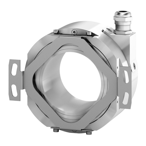
ASC85
• Singleturn rotary encoder with optical scanning
• Large 50 mm / 1.9685" thru-bore shaft
• Resolution up to 25 bits, high accuracy ±0.005°
• SSI and BiSS C-mode interfaces
• Sine-Cosine 1Vpp additional track
• For direct integration into robots, radars and motors
Suitable for the following models:
ASC85xx/BG...
•
ASC85xx/GG...
•
ASC85xx/SC...
•
Lika Electronic
User's guide
•
Tel. +39 0445 806600
Table of Contents
•
info@lika.biz
11
12
14
17
21
41
•
www.lika.biz
9
Advertisement
Table of Contents

Related Manuals for Lika ASC85


Summary of Contents for Lika ASC85
-
Page 1: Table Of Contents
User's guide Smart encoders & actuators ASC85 • Singleturn rotary encoder with optical scanning • Large 50 mm / 1.9685" thru-bore shaft • Resolution up to 25 bits, high accuracy ±0.005° • SSI and BiSS C-mode interfaces • Sine-Cosine 1Vpp additional track •... - Page 2 Tous droits réservés. This document and information contained herein are the property of Lika Electronic s.r.l. and shall not be reproduced in whole or in part without prior written approval of Lika Electronic s.r.l. Translation, reproduction and total or partial modification (photostat copies, film and microfilm included and any other means) are forbidden without written authorisation of Lika Electronic s.r.l.
-
Page 3: General Contents
1.1 Safety......................................9 1.2 Electrical safety..................................9 1.3 Mechanical safety................................10 2 - Identification............................11 3 - Mounting instructions......................... 12 3.1 ASC85 encumbrance sizes...............................12 3.2 Mechanical characteristics of the mounting support..................12 3.3 Mounting the encoder..............................12 4 - Electrical connections........................... 14 4.1 M23 12-pin connector..............................14 4.2 M12 12-pin connector..............................15... - Page 4 Save parameters on EEPROM..........................26 Save parameters and activate Preset / Offset....................26 Load and save default parameters........................26 Configuration................................27 Set preset / offset..............................27 Enable preset / offset............................28 Output code................................28 Code sequence.................................28 Counts per revolution............................29 Number of revolutions............................29 Preset / Offset................................30 Device type..................................31 N°...
- Page 5 7 - 1Vpp Sine/Cosine output signals....................... 41 7.1 Output signals voltage level............................41 8 - Default parameters list........................42...
-
Page 6: Subject Index
Subject Index Interpolator error active..........32 Absolute data error............34 AC maximum amplitude..........36 Manufacturer ID...............38 AC minimum amplitude..........35 Active errors...............32 N° of bits used for multiturn........31 Amplitude control maximum current.....36 N° of bits used for singleturn........31 Amplitude control minimum current......36 Number of revolutions..........29 Bank selection..............25 Position.................22 Preset / Offset..............30... -
Page 7: Typographic And Iconographic Conventions
In this guide, to make it easier to understand and read the text the following typographic and iconographic conventions are used: parameters and objects both of Lika device and interface are coloured in GREEN; • alarms are coloured in RED;... -
Page 8: Preliminary Information
ASC85 absolute encoders with SSI / BiSS C-mode interface. ASC85 is the large thru-bore rotary encoder with high singleturn resolution up to 25 bits and high accuracy ±0.005°. This encoder is able to provide a total amount of position information up to 25 bits (25 bits = 33,554,432 cpr). -
Page 9: Safety Summary
• failure to comply with these precautions or with specific warnings elsewhere in this manual violates safety standards of design, manufacture, and intended use of the equipment; • Lika Electronic assumes no liability for the customer's failure to comply with these requirements. 1.2 Electrical safety •... -
Page 10: Mechanical Safety
ASC85 SSI & BiSS C-mode 1.3 Mechanical safety • Install the device following strictly the information in the “3 - Mounting instructions” section on page 12; • mechanical installation has to be carried out with stationary mechanical parts; • do not disassemble the encoder;... -
Page 11: Identification
Information is listed in the delivery document too. Please always quote the order code and the serial number when reaching Lika Electronic. For any information on the technical characteristics of the product refer to the technical catalogue. -
Page 12: Mounting Instructions
ASC85 SSI & BiSS C-mode 3 - Mounting instructions WARNING Installation must be carried out by qualified personnel only, with power supply disconnected and mechanical parts compulsorily in stop. 3.1 ASC85 encumbrance sizes (values are expressed in mm) 3.2 Mechanical characteristics of the mounting support (values are expressed in mm) 3.3 Mounting the encoder... - Page 13 ASC85 SSI & BiSS C-mode Mount the encoder on the motor shaft. Avoid forcing the encoder shaft; fasten the fixing plate 1 to the rear of the motor using four M4 screws with washers 2; max. tightening torque: 2 ±0.2 Nm;...
-
Page 14: Electrical Connections
ASC85 SSI & BiSS C-mode 4 - Electrical connections WARNING Power supply must be turned off before performing any electrical connection! If wires of unused signals come in contact, irreparable damage could be caused to the device. Thus they must be cut at different lengths and insulated singularly. -
Page 15: M12 12-Pin Connector
ASC85 SSI & BiSS C-mode 4.2 M12 12-pin connector M12 12-pin connector Male frontal side 4.3 TF12 cable specifications Model : LIKA TF12 encoder cable Cross section : 6 x 2 twisted pairs (28 AWG) Jacket : special flame retardant PVC compound Shield : tinned copper braid, coverage >... -
Page 16: Zero Setting Input
ASC85 SSI & BiSS C-mode when the encoder shaft rotates counter-clockwise. If not used, connect the Counting direction input to 0Vdc (standard counting direction, see the Figure). WARNING After changing the counting direction you are required to set a new zero. -
Page 17: Ssi Interface
ASC85 SSI & BiSS C-mode 5 - SSI interface Order code: ASC85xx/BG... ASC85xx/GG... 5.1 SSI (Synchronous Serial Interface) Synchronous Serial (the acronym Interface) is a synchronous point-to-point serial interface engineered unidirectional data transmission between one Master and one Slave. Developed in the first eighties, it is based on the RS- 422 serial standard. -
Page 18: Msb Left Aligned" Protocol
ASC85 SSI & BiSS C-mode At each change of the clock signal and at each subsequent rising edge (2) one bit is clocked out at a time, up to LSB, so completing the data word transmission. The cycle ends at the last rising edge of the clock signal (3). This means that up to n + 1 rising edges of the clock signals are required for each data word transmission (where n is the bit resolution);... -
Page 19: Recommended Transmission Rates
ASC85 SSI & BiSS C-mode Structure of the position information ASC8520/... … ASC8525/... … value … 5.3 Recommended transmission rates The SSI interface has a frequency of data transmission ranging between 100 kHz and 4 MHz. CLOCK IN and DATA OUT signals comply with the “EIA standard RS-422”. -
Page 20: Recommended Ssi Input Circuit
ASC85 SSI & BiSS C-mode 5.4 Recommended SSI input circuit MAN ASC85 SSI_BiSS E 1.6.odt 5 - SSI interface 20 of 44... -
Page 21: Biss C-Mode Interface
6 - BiSS C-mode interface Order code: ASC85xx/SC... Lika encoders are always Slave devices and comply with the “BiSS C-mode interface” and the “Standard encoder profile”. Refer to the official BiSS website for all information not listed in this manual (www.biss-interface.com). -
Page 22: Single Cycle Data Scd
ASC85 SSI & BiSS C-mode 6.2 Single Cycle Data SCD 6.2.1 SCD structure SCD data has a variable length according to the resolution of the encoder. It is nbitres+8 long where “nbitres” is the resolution of the encoder expressed in bits. -
Page 23: Crc
ASC85 SSI & BiSS C-mode (6 bits) Correct transmission control (inverted output). Cyclic Redundancy Check is an error checking which is the result of a “Redundancy Checking” calculation performed on the message contents. This is intended to check whether transmission has been performed properly. It is 6-bit long. -
Page 24: Crc
ASC85 SSI & BiSS C-mode Data bit structure: … … … … Correct transmission control (inverted output). Cyclic Redundancy Check is an error checking which is the result of a “Redundancy Checking” calculation performed on the message contents. This is intended to check whether transmission has been performed properly. -
Page 25: Bank Selection
- Default parameter value is written in bold. Bank selection [40, rw] ASC85 encoder is equipped with an internal EEPROM that offers the user 7 kbit of additional storage space for user data. The EEPROM is organized in 16 memory banks. -
Page 26: Profile Id
ASC85 SSI & BiSS C-mode Profile ID [42 - 43, ro] These registers contain the identification code of the used profile. The used encoder profile is BP1: Standard Encoder Profile. Default value for the Profile ID is: Register Singleturn resolution,... -
Page 27: Configuration
Load and save default parameters: default parameters are set at the factory by Lika Electronic engineers to allow the operator to run the device for standard operation in a safe mode. As soon as the command is sent the default parameters are uploaded and activated. -
Page 28: Enable Preset / Offset
ASC85 SSI & BiSS C-mode Preset / Offset register is used to set the offset, i.e. the system adds an offset to the actual position: position = actual position + Offset. To activate the preset / offset value use the Save parameters and activate Preset / Offset... -
Page 29: Counts Per Revolution
ASC85 SSI & BiSS C-mode Counts per revolution [4A … 4D, rw] Register Counts per revolution … 2 … 2 … 2 … 2 These registers set the number of counts (information) per revolution (singleturn resolution). You are allowed to set whatever integer value less than or equal to the number of physical information per revolution. -
Page 30: Preset / Offset
ASC85 SSI & BiSS C-mode “Hardware number of turns” = 1 turn = 25 bits (33,554,432 1 = 33,554,432) “Hardware total resolution” Let's suppose you need to set the encoder as follows: 2,048 steps per revolution 1 turn: “Counts per... -
Page 31: Device Type
ASC85 SSI & BiSS C-mode then send the Save parameters and activate Preset / Offset • Command command in the register (set “02” in the register 48). Preset / Offset structure: Register … … Use the “Save parameters and activate Preset / Offset” function (set “02” in the register 48 Command) to store and activate the new value. -
Page 32: Active Errors
ASC85 SSI & BiSS C-mode Active errors [74, ro] This register is meant to warn that an error condition is active in the sensors 1, Sensor in the sensor 2, or in the interpolator (the relevant bit = “1”). Register 75... -
Page 33: Sensor 1 And Interpolator Error Register
ASC85 SSI & BiSS C-mode Bits 4 … 7 Not used. Sensor 1 and Interpolator error register [75, ro] This register is meant to show the fault that is currently active in the sensor 1 or in the interpolator. In some cases the type of fault is further specified by... -
Page 34: Synchronization Error
ASC85 SSI & BiSS C-mode Bit 3 Synchronization error When this bit has logic level high 1 = ACTIVE ERROR, it indicates that a failure occurred in the internal synchronization between the cycle counter and the interpolator. Bit 4 Configuration error When this bit has logic level high 1 = ACTIVE ERROR, it indicates that a configuration error is currently active. -
Page 35: Diagnosis Register
ASC85 SSI & BiSS C-mode Diagnosis register [76, ro] This register offers diagnostic information and specifies the kind of problem Control error Signal error signalled through bit 0 or bit 1 in the register 75 Sensor 1 and Interpolator error register, see on page 33. -
Page 36: Amplitude Control Minimum Current
ASC85 SSI & BiSS C-mode Bit 3 Amplitude control minimum current Control error This error is active simultaneously with the bit 0 in the register 75 Sensor 1 and Interpolator error register, see on page 33. The monitoring circuit of the Amplitude Control output current has detected the lower threshold (minimum current). -
Page 37: Sensor 2 Error Register
ASC85 SSI & BiSS C-mode Sensor 2 error register [77, ro] This register is meant to show the fault that is currently active in the sensor 2. Sensor 2 error The bits in this register are active simultaneously with the bit 0... -
Page 38: External Error
ASC85 SSI & BiSS C-mode Bit 6 External error When this bit has logic level high 1 = ACTIVE ERROR, it indicates that an external error or an internal error occurred. Bit 7 Not used. Device ID [78 … 7D, ro] These registers contain the Device ID (name and software release). -
Page 39: Application Notes
ASC85 SSI & BiSS C-mode 6.5 Application notes Data transmission: Parameter Value Clock Frequency Min 100 KHz, max 10 MHz adaptive (typically 0.35 µs @ BiSS time-out 10 MHz) 6.6 EXAMPLES All values are expressed in hexadecimal notation. 6.6.1 Setting the... -
Page 40: Setting The Preset / Offset
ASC85 SSI & BiSS C-mode 6.6.2 Setting the Preset / Offset After having activated the PRESET function (Enable preset / offset = 0 = ENABLE; Set preset / offset = 0 = PRESET in the Configuration register, see the previous section), you want to set the new Preset value = 100000... -
Page 41: 1Vpp Sine/Cosine Output Signals
ASC85 SSI & BiSS C-mode 7 - 1Vpp Sine/Cosine output signals A (COSINE) and B (SINE) signals are to be intended with CW rotation as viewed in the Figure on page 16. They provide 4,096 sinusoidal waves per mechanical revolution with amplitude 1Vpp. 1Vpp output level results from differential signals detection. - Page 42 ASC85 SSI & BiSS C-mode 8 - Default parameters list BiSS C-mode interface Parameters list Default value * Bank selection Profile ID 28 19 specific for each Serial number device Command Configuration Bit 0 not used 0 = Preset Bit 1 Set preset / offset...
- Page 43 This page intentionally left blank...
- Page 44 Ce dispositif doit être alimenté par un circuit de Classe 2 ou à très basse tension ou bien en appliquant une tension maxi de 30Vcc. Voir le code de commande pour la tension d'alimentation. Lika Electronic Via S. Lorenzo, 25 •...
Need help?
Do you have a question about the ASC85 and is the answer not in the manual?
Questions and answers