
Subscribe to Our Youtube Channel
Related Manuals for Lika AM58K CB Series


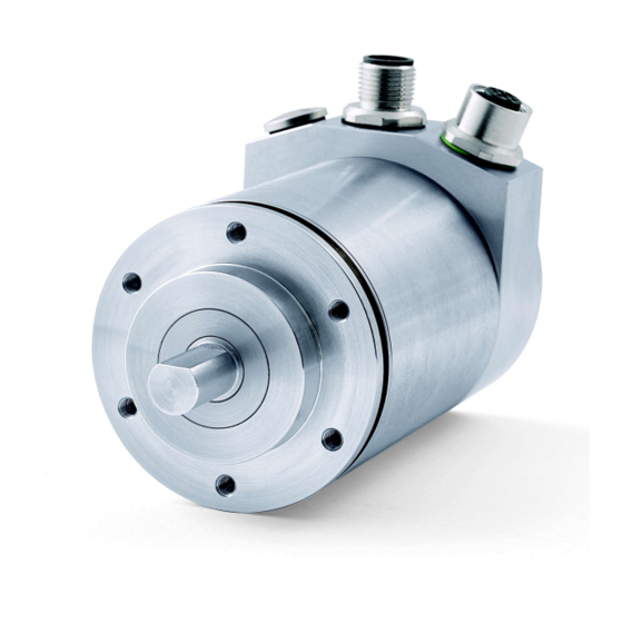
Summary of Contents for Lika AM58K CB Series
-
Page 1: User's Guide
User's guide AM58K CB DS406 - Device profile for encoder Smart encoders & actuators... - Page 2 Tous droits réservés. This document and information contained herein are the property of Lika Electronic s.r.l. and shall not be reproduced in whole or in part without prior written approval of Lika Electronic s.r.l. Translation, reproduction and total or partial modification (photostat copies, film and microfilm included and any other means) are forbidden without written authorisation of Lika Electronic s.r.l.
-
Page 3: Table Of Contents
General contents User's guide......................................1 General contents....................................3 Subject index......................................6 Typographic and iconographic conventions..........................7 Preliminary information..................................8 1 - Safety summary..................................9 2 - Identification.....................................10 3 - Mounting instructions................................11 3.1 Solid shaft encoders................................11 3.1.1 Customary installation..............................11 3.1.2 With fixing clamps (code LKM-386)........................11 3.1.3 With mounting bell (code PF4256)........................12 4 - Electrical connections................................13 4.1 Connection cap..................................13 4.2 Ground connection................................14... - Page 4 1001-00 Error register..............................28 1003 Pre-defined error field...........................28 1005-00 COB_ID SYNC message..........................29 1008-00 Name of device manufacturer......................29 1009-00 Hardware version............................29 100A-00 Software version............................29 100C-00 Guard time..............................29 100D-00 Life time factor............................29 1010-01 Store parameters............................30 1011-01 Restore default parameters........................30 1014-00 COB-ID EMCY..............................31 1015-00 Inhibit time EMCY............................31 1018 Identification object............................31...
- Page 5 6507-00 Profile and software version......................46 6508-00 Operating time............................46 6509-00 Offset value..............................46 650A-01 Manufacturer offset value........................46 650B-00 Serial number..............................46 6.9 Warning objects...................................47 6.10 Emergency objects................................47 6.11 Node guarding protocol..............................48 7 – Setting-up....................................49 8 – Default parameters list.................................52...
-
Page 6: Subject Index
Subject index 6504-00 Supported alarms.........46 6506-00 Supported warnings........46 1000-00 Device type............28 6507-00 Profile and software version....46 1001-00 Error register...........28 6508-00 Operating time..........46 1003 Pre-defined error field........28 6509-00 Offset value.............46 1005-00 COB_ID SYNC message.......29 650A-01 Manufacturer offset value.......46 1008-00 Name of device manufacturer....29 650B-00 Serial number..........46 1009-00 Hardware version..........29 100A-00 Software version...........29... -
Page 7: Typographic And Iconographic Conventions
Typographic and iconographic conventions In this guide, to make it easier to understand and read the text the following typographic and iconographic conventions are used: parameters and objects both of the device and the interface are coloured in ORANGE; • alarms are coloured in RED;... -
Page 8: Preliminary Information
Preliminary information This guide is designed to describe the technical characteristics, installation and use of the CANopen encoders of the AM58K series. These encoders are offered with AISI 303 stainless steel enclosure and specific increased characteristics to withstand the harsh requirements of the food & beverage industry as well as the most aggressive operating environments such as chemical and petrochemical industry, mobile equipment, marine installations, pharmaceutical, medical and surgical applications. -
Page 9: Safety Summary
failure to comply with these precautions or with specific warnings elsewhere in this manual violates safety standards of design, manufacture, and intended use of the equipment; Lika Electronic s.r.l. assumes no liability for the customer's failure to comply with these requirements. Electrical safety ... -
Page 10: Identification
Information is listed in the delivery document too. Please always quote the ordering code and the serial number when reaching Lika Electronic s.r.l. for purchasing spare parts or needing assistance. For any information on the technical characteristics of the product refer to the technical catalogue. -
Page 11: Mounting Instructions
AM58K CANopen® 3 - Mounting instructions WARNING Installation and maintenance operations have to be carried out by qualified personnel only, with power supply disconnected and mechanical parts absolutely in stop. 3.1 Solid shaft encoders • Mount the flexible coupling 1 on the encoder shaft; •... -
Page 12: With Mounting Bell (Code Pf4256)
AM58K CANopen® 3.1.3 With mounting bell (code PF4256) MAN AM58K CB E 1.1.odt 3 - Mounting instructions... -
Page 13: Electrical Connections
AM58K CANopen® 4 - Electrical connections WARNING Power supply must be turned off before performing any electrical connection! 4.1 Connection cap WARNING Do not remove or mount the connection cap with power supply switched ON. Damage may be caused to internal components. The terminal connectors for connecting the power supply and the BUS IN and BUS OUT cables as well as the dip-switches meant to set the baud rate and the node ID and activate the termination resistance are located inside the encoder... -
Page 14: Ground Connection
AM58K CANopen® 4.2 Ground connection Minimize noise by connecting the shield and/or the connector housing and/or the frame to ground. Make sure that ground is not affected by noise. The connection point to ground can be situated both on the device side and on user’s side. -
Page 15: Connection Cap With M12 Connectors
AM58K CANopen® 4.4 Connection cap with M12 connectors The connection cap has two M12 connectors with pin-out in compliance with CANopen® standard. Therefore you can use standard CAN cables commercially available. M12 connector A coding (frontal side) male female (BUS IN) (BUS OUT) Description Case... -
Page 16: Rt Bus Termination
AM58K CANopen® 4.6 RT Bus termination WARNING Power supply must be turned off before performing this operation! A bus termination resistance is provided in the connection cap and has to be activated as line termination in the last device of the transmission line. Use RT Switch to activate or deactivate the bus termination. -
Page 17: Baud Rate: Dip A
AM58K CANopen® 4.8 Baud rate: DIP A WARNING Power supply must be turned off before performing this operation! Transmission rate can be set either via hardware or via software. If DIP A bit 4 = ”OFF” the bit rate is set through object 3000-00 Baud rate the “Object Dictionary”... -
Page 18: Node Number: Dip B
AM58K CANopen® 4.9 Node number: DIP B WARNING Power supply must be turned off before performing this operation! Node number can be set both via hardware or via software. Allowed node addresses range between 1 and 127. The default value is 1. If all bits of DIP B are ”OFF”... -
Page 19: Quick Reference
AM58K CANopen® 5 - Quick reference 5.1 Hardware resolution WARNING Make sure the physical resolution of the encoder matches the set resolution. Different resolutions may be set if the encoder and the connection cap have been ordered / supplied separately. Examples 6501-00 Hardware counts per revolution AM58K 13/4096CB-xx... - Page 20 AM58K CANopen® Encoder Master COB-ID Index Process data 580+ID Step 3 - Set object 6502-00 Hardware number of turns See resolution table below in the page for B4, B5, B6 and B7 values. Master Encoder COB-ID Index Process data 600+ID Encoder ...
-
Page 21: Using The Default Settings
AM58K CANopen® 5.2 Using the default settings Using the default settings provided by the manufacturer, you can switch on the device and read immediately its position. Follow the instructions below to: read the device resolution; set the operational mode;... -
Page 22: Canopen® Interface
AM58K CANopen® 6 - CANopen® interface Lika encoders are always slave devices and comply with “Device profile for encoders”, Class 2. For any omitted information, refer to the “CiA Draft Standard 301” and “CiA Draft Standard 406” documents available at www.can-cia.org. -
Page 23: Initialization State
AM58K CANopen® 6.2.1 Initialization state This is the first state the CANopen® device enters after power is turned on or after a hardware reset. As soon as the basic CANopen® device initialization is carried out, device reads and loads the parameters saved on EPROM, sends a Pre-operational boot-up message and then switches automatically to state. -
Page 24: Communication Objects
AM58K CANopen® 6.3 Communication objects Four different kinds of communication messages are used in a CANopen® network: Network management NMT protocol: NMT protocols are used to issue state machine change commands (i.e. to start and stop the devices), detect remote device boot-ups and error conditions. -
Page 25: Nmt Objects
AM58K CANopen® 6.4 NMT objects NMT structure: COB-ID (11 bit) 2 CAN Data Bytes Func.code Node ID Command Slave ID 0000 NMT Func. Slave ID If Slave ID = 00h, the NMT message is issued to all network nodes. NMT Function: Command NMT Function State node... -
Page 26: Pdo Objects
AM58K CANopen® 6.6 PDO objects PDO (tx) messages are always made up of 4 CAN Data Bytes and are used by the encoder to transmit the position value and/or the velocity value. PDO structure: IDENTIFIER 4 CAN Data Bytes COB-ID(hex) Byte 0 Byte 1 Byte 2... -
Page 27: Sdo Objects
AM58K CANopen® 6.7 SDO objects SDO messages are used to set and read values from the object dictionary of the encoder. These parameters are described in the “Object dictionary” section (page 28). 4 bytes at the most are used for CAN data, other 4 bytes are used for Command, Index and Sub-index fields. -
Page 28: Object Dictionary
AM58K CANopen® 6.8 Object dictionary In the following pages the objects implemented are listed and described as follows: Index-subindex Object name [data types, attribute] Index and subindex are expressed in hexadecimal notation. Attribute: ro = read only access rw = read and write access Unsigned16 data type: Process data bytes... -
Page 29: 1005-00 Cob_Id Sync
[Unsigned32, rw] Default = 0000 0080h 1008-00 Name of device manufacturer [String, ro] It shows the name of the device manufacturer. Default = “LIKA SRL” 1009-00 Hardware version [String, ro] It shows the hardware version of the device. 100A-00 Software version [String, ro] It shows the software version of the device. -
Page 30: 1010-01 Store Parameters
[Unsig32, rw] This object allows the operator to restore all parameters to default values (default values are set at the factory by Lika Electronic engineers to allow the operator to run the device for standard operation in a safe mode). -
Page 31: 1014-00 Cob-Id Emcy
AM58K CANopen® 1014-00 COB-ID EMCY [Unsigned32, rw] This object defines the COB-ID used for sending emergency messages (EMCY). If the node address is set using the internal dip-switches (i.e. at least one dip- switch for setting the node has HIGH logic level = 1), when the power is turned on, this object is always forced to the default value. - Page 32 AM58K CANopen® WARNING It is mandatory to set the bit 30 of COB-ID to 1 (value 0 is not allowed). This means that “No RTR is allowed on the PDO”. If the node address is set using the internal dip-switches (i.e. at least one dip-switch for setting the node has HIGH logic level = 1), when the power is turned on, this object is always forced to the default value.
-
Page 33: 1801 Pdo2 Parameters
AM58K CANopen® 1801 PDO2 parameters PDO2 message is used by default for synchronous transmission of the position value. For more information refer to section “6.6 PDO objects” on page 26. 01 COB-ID of the PDO2 [Unsigned32, rw] Bit number Value Meaning PDO exists / is valid 31 (MSB) -
Page 34: 1802 Pdo3 Parameters
AM58K CANopen® Position value is transmitted after the set number of SYNC commands. 1801 PDO2 Interval in SYNC commands must be set next to this object parameters, sub 2. WARNING Transmission Type Following an attempt to set the to 0, the value is accepted but the PDO message is not sent;... -
Page 35: 1803 Pdo4 Parameters
AM58K CANopen® 02 Transmission type [Unsigned8, rw] Transmission type PDO transmission 00h (0) Acyclic, synchronous not implemented 01h … F0h (1 … 240) Cyclic, synchronous implemented F1h … FBh (241 … 251) not implemented - reserved FCh (252) Synchronous, RTR only not implemented FDh (253) Asynchronous, RTR only not implemented... - Page 36 AM58K CANopen® 29-bit ID (CAN 2.0B) if bit 29 = 0 28 … 11 if bit 29 = 1: bits 28-11 of 29-bit-COB-ID 10 … 0 (LSB) bits 10-0 of COB-ID Default = C000 0480h+NodeID (no RTR, COB-ID) WARNING It is mandatory to set the bit 30 of COB-ID to 1 (value 0 is not allowed). This means that “No RTR is allowed on the PDO”.
-
Page 37: 1A00-01 Pdo1 Mapping Parameter
AM58K CANopen® NOTE - Transmission of PDO1, PDO2, PDO3 and PDO4 messages can be enabled (or disabled) by setting to “0” (or “1”) the most significant bit (MSB) used by PDO (object 180xh, sub1). - Cyclic transmission or synchronous transmission can be modified by setting the object 180xh sub 2:... -
Page 38: Manufacturer Specific Objects
AM58K CANopen® 6.8.2 Manufacturer specific objects 2104-00 Limit switch min. [Unsigned32, rw] This object can be used to set the lowest software limit switch (-). If the encoder position is below the value set in this object, bit 12 of object 6500-00 Operating states will be set to 1. -
Page 39: 3001-00 Node-Id
AM58K CANopen® Master Encoder COB-ID Index Data byte 600+ID see table Encoder Master (confirmation) COB-ID Index Data byte 580+ID Master Encoder (Reset node) COB-ID Slave ID Set the master device to the new baud rate: Encoder Master (Boot-up with new baud rate) COB-ID 700+ID NOTE... -
Page 40: 3005-00 Velocity Format
AM58K CANopen® Master Encoder (Reset node) COB-ID Slave ID old ID Encoder Master (Boot-up with new Node-ID) COB-ID 700+ID NOTE To save the new Node-ID value execute the store parameters function (see 1010-01 Store parameters). object When the power is turned off, parameters not saved will be lost. 3005-00 Velocity format [Unsigned8, rw] This attribute defines the engineering units for the velocity value. -
Page 41: Device Profile Objects (Ds 406)
AM58K CANopen® 6.8.3 Device profile objects (DS 406) 6000-00 Operating parameters [Unsigned16, rw] Function bit = 0 bit = 1 CCW (counter Code sequence (clockwise) clockwise) not used Scaling function disabled enabled 3…11 not used Limit switch min. disabled enabled Limit switch max. -
Page 42: 6001-00 Counts Per Revolution
AM58K CANopen® 6001-00 Counts per revolution [Unsig32, rw] This object sets a custom number of distinguishable steps per revolution. Scaling function 6000-00 Operating Enabled if bit 2 in the object parameters = ”1”. To avoid counting errors, check that 6501-00 Hardware counts per revolution = integer value. -
Page 43: 6003-00 Preset Value
AM58K CANopen® Example Multiturn encoder AM58K13/4096CB-6 Resolution is: Hardware counts per revolution: 6501-00 Hardware counts revolution = 8192 (2 6502-00 Hardware number of turns Hardware number of turns: 4096 (2 Total hardware resolution: = 33554432 (2 2048 counts/rev. 1024 turns are required: 6000-00 Operating parameters, bit 2 = “1”... -
Page 44: 6004-00 Position Value
AM58K CANopen® 6004-00 Position value [Unsigned32, ro] This object contains the position value, transmitted value is calculated considering the scaling values. Value is transmitted cyclically or synchronously 1800 PDO1 parameters, 1801 PDO2 according to the settings in the objects parameters 1802 PDO3 parameters. -
Page 45: Scaling Function
AM58K CANopen® Scaling function It shows whether the scaling function is disabled or enabled. To disable / enable Scaling function the scaling function you must set the bit 2 of the object 6000-00 Operating parameters to 0 / 1. Limit switch min. 2104-00 Limit If the encoder position is over the value set in the object switch... -
Page 46: 6504-00 Supported Alarms
AM58K CANopen® 6504-00 Supported alarms [Unsigned16, ro] Default = 0000h (Alarms not supported). 6506-00 Supported warnings [Unsigned16, ro] Default = 0000h (Warnings not supported). 6507-00 Profile and software version [Unsig32, ro] Contains the profile and software version. Profile version for encoders = 3.1 Software version = 1.1 Default = 0301 0101h 6508-00 Operating time... -
Page 47: Warning Objects
AM58K CANopen® 6.9 Warning objects For the complete list and meaning of the warning messages please refer to “SDO abort codes” section in “CiA Draft Standard 301” document available at www.can-cia.org. 6.10 Emergency objects Emergency (EMCY) objects are issued by the device when an internal error occurs. -
Page 48: Node Guarding Protocol
AM58K CANopen® 6.11 Node guarding protocol At system boot the “Node guarding protocol” is disabled; this protocol is enabled automatically as soon as the master device sends a RTR message (Remote Transmission Request) the first time. Master Slave request response Guard NodeGuard. -
Page 49: Setting-Up
AM58K CANopen® 7 – Setting-up Here following are some examples of transmission between Master and Slave devices. A generic “ID” value is used to indicate the encoder address; Master address is always 0. All values are expressed in hexadecimal notation. Set Operational, Pre-operational state... - Page 50 AM58K CANopen® Set the preset value 6003-00 Preset value (preset = 1000 = 03E8h) Master Encoder (Set request) COB-ID Index Process data 600+ID Encoder Master (Set confirmation) COB-ID Index Process data 580+ID Set Sync counter 1801 PDO2 parameters, sub 2 (n = 5 = 05h) Master ...
- Page 51 AM58K CANopen® Enable Cyclic mode 6200-00 Cyclic time Set cyclic time (100 ms = 64h) Master Encoder (Set request) COB-ID Index Process data 600+ID Encoder Master (Set confirmation) COB-ID Index Process data 580+ID (1800 PDO1 parameters, sub 1): Read COB-ID used by PDO1 Master ...
-
Page 52: Default Parameters List
1000-00 Device type 0x00020196 1001-00 Error register 0x00 1003 Pre-defined error field 1005-00 COB_ID SYNC message 0x00000080 1008-00 Name of device LIKA SRL* manufacturer 1009-00 Hardware version 100A-00 Software version 100C-00 Guard time 0x0000 100D-00 Life time factor 0x00 1014-00 COB-ID EMCY... - Page 53 Page intentionally left blank...
- Page 54 Page intentionally left blank...
- Page 55 Page intentionally left blank...
- Page 56 Vdc. Refer to the product datasheet for supply voltage rate. Dispose separately LIKA Electronic Via S. Lorenzo, 25 - 36010 Carrè (VI) - Italy Tel. +39 0445 806600 Fax +39 0445 806699 Italy: eMail info@lika.it - www.lika.it World: eMail info@lika.biz - www.lika.biz...
Need help?
Do you have a question about the AM58K CB Series and is the answer not in the manual?
Questions and answers