Table of Contents
Advertisement
Quick Links
USER MANUAL
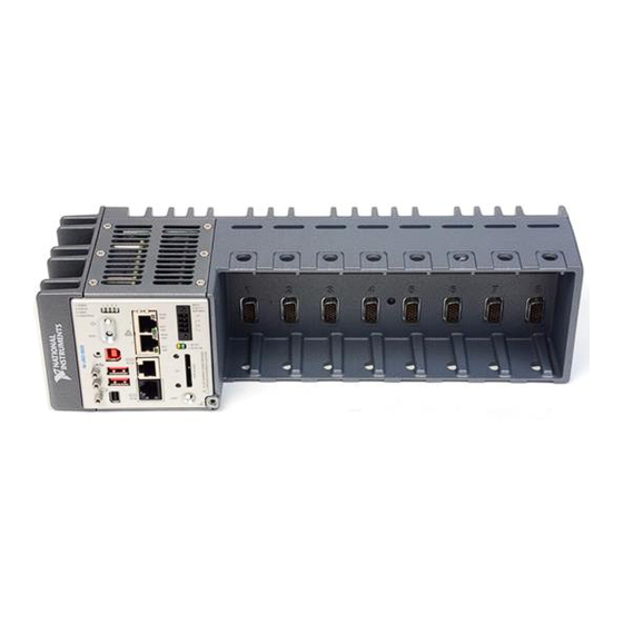
NI cRIO-9035
Embedded CompactRIO Controller with Real-Time Processor and
Reconfigurable FPGA
This document describes the features of the NI cRIO-9035 and NI cRIO-9035 Sync and
contains information about mounting and operating the device.
In this document, the NI cRIO-9035 and NI cRIO-9035 Sync are inclusively referred to as the
cRIO-9035.
For more information about timing and synchronization capabilities of NI cRIO-9035 Sync,
visit
ni.com/info
and enter the Info Code
.
cRIO9035sync
Advertisement
Table of Contents

Related Manuals for National Instruments NI cRIO-9035


Summary of Contents for National Instruments NI cRIO-9035
- Page 1 This document describes the features of the NI cRIO-9035 and NI cRIO-9035 Sync and contains information about mounting and operating the device. In this document, the NI cRIO-9035 and NI cRIO-9035 Sync are inclusively referred to as the cRIO-9035. For more information about timing and synchronization capabilities of NI cRIO-9035 Sync, visit ni.com/info...
-
Page 2: Table Of Contents
Features........................6 Ports and Connectors......................6 Buttons..........................14 LEDs..........................16 Chassis Grounding Screw....................20 Internal Real-Time Clock....................21 CMOS Battery.........................21 File System........................21 Installing the Module Immobilization Accessory..............22 Module Immobilization Accessory Dimensions.............23 2 | ni.com | NI cRIO-9035 User Manual... -
Page 3: Configuring The Crio-9035
Ethernet hub using a standard Category 5 (CAT-5) or better shielded, twisted-pair Ethernet cable. Caution To prevent data loss and to maintain the integrity of your Ethernet installation, do not use a cable longer than 100 m (328 ft). NI cRIO-9035 User Manual | © National Instruments | 3... - Page 4 Launch MAX on the host computer. Expand Remote Systems in the configuration tree and locate your system. MAX lists the system under the model number followed by the serial number, such as NI-CRIO-9035-1856AAA. 4 | ni.com | NI cRIO-9035 User Manual...
-
Page 5: Configuring Startup Options
Eight data bits • No parity • One stop bit • No flow control Disable RT Rebooting the cRIO-9035 with this setting on prevents any LabVIEW Startup App startup applications from running. NI cRIO-9035 User Manual | © National Instruments | 5... -
Page 6: Crio-9035 Features
Embedded UI to Access RT Target VIs topic in the LabVIEW Help. cRIO-9035 Features The cRIO-9035 provides the following features. Ports and Connectors The cRIO-9035 provides the following ports and connectors. 6 | ni.com | NI cRIO-9035 User Manual... - Page 7 No Connect RX_D+ No Connect RX_D- Note Both Ethernet ports perform automatic crossover configuration so you do not need to use a crossover cable to connect to a host computer. NI cRIO-9035 User Manual | © National Instruments | 7...
- Page 8 Table 5. Power Accessories Accessory Part Number NI PS-15 Power Supply, 24 VDC, 5 A, 100-120/200-240 VAC Input 781093-01 NI PS-10 Desktop Power Supply, 24 VDC, 5 A, 100-120/200-240 VAC Input 782698-01 8 | ni.com | NI cRIO-9035 User Manual...
- Page 9 The cRIO-9035 has an RS-232 serial port that is implemented with an RJ-50, 10-position modular jack to which you can connect devices such as displays or input devices. Use the NI cRIO-9035 User Manual | © National Instruments | 9...
- Page 10 The following accessories are available to connect the RS-232 serial port to a 9-pin DSUB plug. Table 8. RS-232 Serial Port Accessories Accessory Length Part Number RS-232, S8 Serial Cable, 10-Position Modular Plug to 9-Pin DSUB 182845-01 182845-02 182845-03 10 | ni.com | NI cRIO-9035 User Manual...
- Page 11 Use the Mini DisplayPort to connect a monitor and implement a local HMI. You can use a single real-time VI to interactively develop both your user interface and system logic. For NI cRIO-9035 User Manual | © National Instruments | 11...
- Page 12 Mini DisplayPort Retention Accessory — 156866-01 USB Host Ports The USB host ports on the cRIO-9035 support common USB mass-storage devices such as USB Flash drives, USB-to-IDE adapters, keyboards, mice, and USB cameras. 12 | ni.com | NI cRIO-9035 User Manual...
- Page 13 EMC standards applicable to your country. What to Use • Ferrite (711849-01), included with the cRIO-9035 • USB cables What to Do Install the ferrite on the USB cables, as shown in the following figure. NI cRIO-9035 User Manual | © National Instruments | 13...
-
Page 14: Buttons
Cable power (5 V) The following NI cable is available for the cRIO-9035. Table 15. USB Device Port Cable Cable Length Part Number NI Locking USB Cable 157788-01 Buttons The cRIO-9035 provides the following buttons. 14 | ni.com | NI cRIO-9035 User Manual... - Page 15 Hold the RESET button again for 5 seconds to boot the controller into safe mode, enable Console Out, and reset network adapters to default settings. System Reset The following figure shows the reset behavior of the cRIO-9035. NI cRIO-9035 User Manual | © National Instruments | 15...
-
Page 16: Leds
The cRIO-9035 has a CMOS reset button that you can use to reset the CMOS and the BIOS. LEDs The cRIO-9035 provides the following LEDs. Figure 5. cRIO-9035 LEDs 1. POWER LED 4. USER FPGA1 LED 2. STATUS LED 5. Gigabit Ethernet LEDs 3. USER1 LED 6. SD LEDs 16 | ni.com | NI cRIO-9035 User Manual... - Page 17 The cRIO-9035 is powered from the V1 input. Yellow Solid The cRIO-9035 is powered from the V2 input. — The cRIO-9035 is powered off. STATUS LED Indicators The following table describes the STATUS LED indicators. NI cRIO-9035 User Manual | © National Instruments | 17...
- Page 18 Remove any shorts and cycle power the cRIO-9035. If the problem persists, contact NI. — The cRIO-9035 is in run mode. Software is installed and the operating system is running. 18 | ni.com | NI cRIO-9035 User Manual...
- Page 19 10 Mbit/s data rate selected SD LED Indicators The cRIO-9035 has two LEDs that indicate the SD card drive mount status and activity. The following table lists SD LED indicators. NI cRIO-9035 User Manual | © National Instruments | 19...
-
Page 20: Chassis Grounding Screw
If you use shielded cabling to connect to a C Series module with a plastic connector, you must attach the cable shield to the chassis grounding terminal using 1.31 mm (16 AWG) or larger wire. Attach a ring lug to the wire and attach the wire 20 | ni.com | NI cRIO-9035 User Manual... -
Page 21: Internal Real-Time Clock
For example, it is possible to link , where /C/ni-rt/system dynamic libraries are deployed on other LabVIEW Real-Time targets, to /usr/local/lib where they are stored on the cRIO-9035, if the application requires this. NI cRIO-9035 User Manual | © National Instruments | 21... -
Page 22: Installing The Module Immobilization Accessory
Torx T10 and T20. The other set is a tamper-resistant set of screws that require a security driver type, Torx T10H and T20H. Use the tamper-resistant set to help prevent unintended modification of the system. 22 | ni.com | NI cRIO-9035 User Manual... -
Page 23: Module Immobilization Accessory Dimensions
NI recommends using a liquid thread locker for all fasteners if the system is expected to experience vibration for an extended amount or time. Module Immobilization Accessory Dimensions The following figure shows the Module Immobilization accessory dimensions for the cRIO-9035. NI cRIO-9035 User Manual | © National Instruments | 23... -
Page 24: Mounting The Crio-9035
Before using any of these mounting methods, record the serial number from the back of the cRIO-9035 so that you can identify the cRIO-9035 in MAX. You will be unable to read the serial number after you mount the cRIO-9035. 24 | ni.com | NI cRIO-9035 User Manual... -
Page 25: Dimensions
Your installation must meet the following requirements for cooling and cabling clearance. Allow 25.4 mm (1.00 in.) on the top and the bottom of the cRIO-9035 for air circulation, as shown in the following figure. NI cRIO-9035 User Manual | © National Instruments | 25... -
Page 26: Ambient Temperature
Measure the ambient temperature at each side of the cRIO-9035, 63.5 mm (2.50 in.) from the side and 38.1 mm (1.50 in.) forward from the rear of the cRIO-9035, as shown in the following figure. 26 | ni.com | NI cRIO-9035 User Manual... -
Page 27: Mounting The Crio-9035 Directly On A Flat Surface
M4 screw (x6), user provided, which must not exceed 8 mm of insertion into the cRIO-9035 What to Do Complete the following steps to mount the cRIO-9035 directly on a flat surface. Prepare the surface for mounting the cRIO-9035 using the Surface Mounting Dimensions. NI cRIO-9035 User Manual | © National Instruments | 27... -
Page 28: Mounting The Crio-9035 On A Panel
Screwdriver, Phillips #2 • NI panel mounting kit, 157253-01 – Panel mounting plate – M4 x 10 screws (x6) What to Do Complete the following steps to mount the cRIO-9035 on a panel. 28 | ni.com | NI cRIO-9035 User Manual... - Page 29 11.1 mm (0.44 in.) 152.4 mm (6.00 in.) 152.4 mm (6.00 in.) 114.3 mm 138.9 mm (4.50 in.) (5.47 in.) 25.4 mm (1.00 in.) 89.9 mm (3.54 in.) 147.3 mm (5.80 in.) NI cRIO-9035 User Manual | © National Instruments | 29...
-
Page 30: Mounting The Crio-9035 On A Din Rail
You must use the screws provided with the NI DIN rail kit because they are the correct depth and thread for the DIN rail clip. Clipping the cRIO-9035 on a DIN Rail Complete the following steps to clip the cRIO-9035 on a DIN rail. 30 | ni.com | NI cRIO-9035 User Manual... -
Page 31: Mounting The Crio-9035 On A Rack
• Screwdriver, Phillips #2 • NI desktop mounting kit, 779473-01 – Desktop mounting brackets (x2) What to Do Complete the following steps to mount the cRIO-9035 on a desktop. NI cRIO-9035 User Manual | © National Instruments | 31... - Page 32 Desktop Mounting Dimensions The following figures show the desktop mounting dimensions for the cRIO-9035. Figure 16. cRIO-9035 Desktop Mounting Front Dimensions 361.7 mm (14.24 in.) 2× 17.2 mm (0.68 in.) 39.1 mm (1.54 in.) 32 | ni.com | NI cRIO-9035 User Manual...
-
Page 33: Bios Configuration
The BIOS settings are preserved even when the CMOS battery is dead, but the system will boot very slowly because the BIOS cannot optimize boot time by saving specific system information to CMOS. NI cRIO-9035 User Manual | © National Instruments | 33... -
Page 34: Bios Setup Utility
Return to the parent menu of a submenu. At the top-level menus, this key serves as a shortcut to the Exit menu. <+>, <-> Cycle between all available settings for a selected configuration option. <Tab> Select time and date fields. 34 | ni.com | NI cRIO-9035 User Manual... -
Page 35: Main Setup Menu
If this happens, restore BIOS settings to the factory defaults. The Advanced setup menu includes the following submenus: • Power/Wake Configuration Submenu • SATA Configuration Submenu • USB Configuration Submenu NI cRIO-9035 User Manual | © National Instruments | 35... - Page 36 Interrupt USB transfers. The default value is 20 seconds. • Device Reset Timeout—This setting specifies the number of seconds the POST waits for a USB mass storage device to start. The default value is 20 seconds. 36 | ni.com | NI cRIO-9035 User Manual...
-
Page 37: Boot Setup Menu
• Hard Drive BBS Priorities Submenu • CD/DVD ROM Drive BBS Priorities Submenu • Floppy Drive BBS Priorities Submenu • Network Device BBS Priorities Submenu NI cRIO-9035 User Manual | © National Instruments | 37... -
Page 38: Save & Exit Menu
The Save & Exit setup menu contains all available options for exiting, saving, and loading the BIOS default configuration. As an alternative to this menu, press <F9> to load optimal BIOS default settings and <F10> to save changes and exit setup. 38 | ni.com | NI cRIO-9035 User Manual... -
Page 39: Worldwide Support And Services
If BIOS setup options have been changed and saved, a reboot will be required and the boot override selection will not be valid. Worldwide Support and Services The National Instruments website is your complete resource for technical support. At ni.com/ support, you have access to everything from troubleshooting and application development self-help resources to email and phone assistance from NI Application Engineers. - Page 40 Other product and company names mentioned herein are trademarks or trade names of their respective companies. For patents covering National Instruments products/technology, refer to the appropriate location: Help»Patents in your software, the file on your media, or the National Instruments Patent Notice at .
Need help?
Do you have a question about the NI cRIO-9035 and is the answer not in the manual?
Questions and answers